OPEN ACCESS
A numerical investigation is presented to illustrate the impact of aspect ratio in a conjugate heat transfer enclosure filled with porous media and partially heated from vertical walls. The left and right walls are partially heated and cooled, respectively. The remaining partitions of the vertical walls in addition to the top and bottom walls are considered to be adiabatic. the present work is limited to two different cases: Top-Bottom (case 1) and Bottom-Top (case 2). The dimensionless Navier-Stokes governing equations are solved using the finite element method. The parameters of interest are the modified Rayleigh number 10 ≤ Ra ≤ 103, the finite wall thickness 0.02 ≤ D ≤ 0.5, 0.1 ≤ Kr ≤ 10 and the aspect ratio 0.5 ≤ A ≤ 10. The results are presented in term of streamlines, isotherms and average Nusselt number for fluid phase and along the solid hot wall. The results indicated that the locations of partially active walls have great influence on heat transfer rate. I was shown that Bottom-Top arrangement gives better heat transfer rate compared to that of Top-Bottom. It was also found that by increasing the Rayleigh number, the rate of heat transfer increased. In contrast, increasing the wall thickness and aspect ratio reduced the heat transfer rate.
porous media, natural convection, partially heated, conjugate
The convective heat transfer in rectangular enclosures filled with porous media has been given a great concern due to its wide applications in engineering, medical and biological sciences, geothermal, agricultures, transpiration cooling, pollution of ground water, technology of food, management of radioactive waste and biological materials.
Numerous researchers investigated the natural convective fluid flow within porous rectangular enclosures using the classical Darcian and Non-Darcian models.
Many studies focused on natural convection flow inside enclosure filled with impermeable media [1-10].
In addition, the conductive-convective (conjugate problem) filled with impermeable media was shown an interest by various researchers because of its wide applications such as the installation of cold storages and buildings with high performance insulation.
Recently, some publications, thoroughly presented by Nield and Bejan [11]. Mbaye et al. [12], numerically investigated analytically free convection in an inclined cavity that is filled with porous media with a finite-thickness wall. Horizontal adiabatic walls were assumed, while the vertical sidewalls were maintained at uniform heat flux ($\overline{\overline{q}}$). Baytas et al. [13] demonstrated, the impact of conjugate heat transfer in a porous cavity which has a square geometry surrounded by two horizontal walls of finite thickness. Two different uniform temperatures were applied along the vertical walls. Their results indicated that, for conductivity ratio of high values, the characteristics of the flow was significantly influenced because of the strong impact of the saturated porous media and the walls of the solid. Similarly, the heat transfer phenomena on conjugate natural convection in a porous enclosure bordered by finite walls was examined by [14]. The obtained results illustrated that the rate of the heat transfer from the higher temperature side to the lower temperature side of cavities decreased due to the conduction effect of the wall. Mahdy et al. [15] studied double diffusive convection near the vertical porous truncated cone that has thermal radiation and magnetic field adding the effects of the variable viscosity. Saeid [16] numerically investigated this problem in a two-dimensional vertical porous enclosure. Adiabatic conditions were applied to the horizontal walls, while the vertical walls of a finite thickness were maintained at isothermal varied temperatures. In their study, as the thermal conductivity ratio and Rayleigh number had increased, the average Nusselt numbers increased. In contrast, increasing the wall thickness caused the average Nusselt number to reduce. The conjugate heat transfer in a porous cavity studied numerically by Al-Amiri et al. [17]. The porous media porosity (ԑ) and the impact of the Darcian number were studied. Saleh and Hashim [18] investigated the internal heat generation influence on a porous cavity. The governing parameters such as Rayleigh number, wall thickness and thermal conductivity ratio were examined. Their main conclusions were that decreasing the wall thickness would increase the maximum fluid temperature. In addition, it increased as soon as the thermal conductivity ratio started to increase. Saravanan and Brinda [19] used thermal nonequilibrium model to study the natural convection heat transfer in a heat generating medium with different boundary conditions.
Saleh et al. [20] studied the impact of the conduction wall applied at the bottom of a square shaped enclosure filled with porous media on the heat transfer rate. They used the power full CFD tool COMSOL Multiphysics software to simulate and solve the dimensionless equations. The results proved that by increasing the Rayleigh number and thermal conductivity ratio, or by decreasing the thickness of the bottom wall, the fluid flow strength circulations and the heat transfer rate will increase. Revnic et al. [21] used finite difference approach to numerically solve natural convection in a bidisperes impermeable medium in a cavity. Numerous researchers such as Bhuvaneswari et al. [22], Roslan et al. [23] Pallab et al. [24], Ahmed et al. [25] and Al-Rashed et al. [26] studied the impact of partially thermally active zones on the rate heat transfer.
Bhuvaneswari et al. [22] used Brinkman-Forchheimer extended Darcy model to numerically examine the impact of aspect ratio in a cavity filled with porous media with partial active zones, and their results display that, the location of active zones significantly impact the heat transfer rate and the behavior of fluid flow in the enclosure. Roslan et al. [23] analyzed a conductive polygon object under various Rayleigh number effects located in a square cavity . They found that the polygon object affected the rate of heat transfer. The influence of partially wall locations on both heat transfer and entropy generation have been examined by Pallab et al. [24].
Numerical investigation of natural heat transfer in an inclined partially heated square enclosure filled with saturated porous media with finite walls thickness from both sides studied by Ahmed et al. [25]. Al-Rashed et al. [26] numerically investigated the natural convection and entropy generation in a three dimensional cubical cavity using finite volume method for four different cases of thermally active walls (Bottom-Bottom, Bottom-Top, Top-Bottom, Middel-Middle). They concluded that the Middle-Middle arrangement produces higher values of average Nusselt numbers. Abdulkadhim et al. [27] used finite element techniques and concluded that increasing the aspect ratio will decrease the heat transfer rate and increase the fluid flow strength.
It can be seen from the previous studies and according to the best knowledge of the authors that conjugate heat transfer in partially thermally active hot and cooled zones in a porous enclosure has not been reported yet. Thus the present work demonstrates the effect of partially thermally active walls in heat transfer rate using thermal equilibrium model and for various modified Rayleigh numbers, finite wall thickness, thermal conductivity ratio and aspect ratio for two different cases of thermally active zones which they are Top-Bottom(case-1) and Bottom-Top (case-2).
2.1 Physical model and assumptions
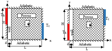
Figure 1 illustrates the schematic diagram of the enclosure filled with porous medium. It can be seen that case-1 (Top-Bottom) and case-2 (Bottom-Top) are partially active thermal zones with finite thickness wall on both sides. Homogeneous, isotropic, and saturated with incompressible fluid assumptions are applied for the porous medium. All properties are assumed to be constant except the density which is described by the Boussinesq approximation.
Figure 1. Schematic diagram of the present problem
2.2 Governing equations
By considering the Cartesian coordinates, two-dimensional porous rectangular cavity was used to model the natural convection fluid flow and heat transfer characteristics. The flow is driven due to buoyancy impact because of temperature variations. The Navier-Stokes governing equations may be written in the form presented below [28]:
The density variation is described by:
$\rho=\rho\left[1-\beta_{T}\left(T-T_{0}\right)\right]$ (1)
For steady natural convection in porous cavity, the two-dimensional equations of continuity, energy and momentum of a fluid in the x and y directions are given by:
Continuity equation:
$\frac{\partial U}{\partial X}+\frac{\partial V}{\partial Y}=0$ (2)
X-momentum equation:
$U \frac{\partial U}{\partial X}+V \frac{\partial U}{\partial Y}=-\frac{\partial P}{\partial X}+P \cdot\left(\frac{\partial^{2} U}{\partial X^{2}}+\frac{\partial^{2} U}{\partial Y^{2}}\right)-\frac{P r}{D a} U ]$ (3)
Y-momentum equation:
$U \frac{\partial V}{\partial X}+V \frac{\partial V}{\partial Y}=-\frac{\partial P}{\partial Y}+P r\left(\frac{\partial V}{\partial X^{2}}+\frac{\partial^{2} V}{\partial Y^{2}}\right)-\frac{P r}{D a} V+R a P_{r} T$ (4)
Energy equation:
$U \cdot \frac{\partial T}{\partial X}+V \cdot \frac{\partial T}{\partial Y}=\frac{\partial^{2} T}{\partial X^{2}}+\frac{\partial^{2} T}{\partial Y^{2}}$ (5)
and the energy equation at the walls:
$\frac{\partial^{2} T_{W}}{\partial X^{2}}+\frac{\partial^{2} T_{W}}{\partial Y^{2}}=0$ (6)
The heat transfer at the walls is defined as in the following:
$N u=\frac{1}{A} \int_{0}^{A}-\frac{\partial T}{\partial X} ) \cdot \partial Y$ (7)
The non-dimensional parameters are:
$X=\frac{x}{L}, Y=\frac{y}{H}, A=\frac{H}{L}, \quad D=\frac{d}{L}, U=\frac{u L}{\alpha}$
$V=\frac{v L}{\alpha}, P=\frac{p L^{2}}{\rho \alpha^{2}}, k_{r}=\frac{k_{w}}{k_{f}}, R a=\frac{g \beta_{T} \Delta T K L}{v \alpha}$
$k_{e f f}=\varepsilon k_{f}+(1-\varepsilon) k_{s}, T=\frac{\overline{T}-\overline{T}_{c}}{\overline{T}_{h}-\overline{T}_{c}}$ (8)
2.3 Boundary conditions
Newtonian, natural, two-dimensional and incompressible flow conditions are assumed in the present study. As mentioned earlier, the fluid flow is driven due to buoyancy caused by variations in temperature. The variation in density was described by the Boussinesq approximation.
Equations (2)-(7) are solved using non-dimensional initial boundary conditions:
|
At X = D |
U = V = 0 |
$\frac{\partial T_{w}}{\partial X}=k, \frac{\partial T}{\partial X}$ |
(9-a) |
|
At X = 1 |
U = V = 0 |
Tc = 0 |
(9-b) |
|
At X = 0 |
Th = 1 |
|
(9-c) |
|
At X = 0,A |
U = V = 0 |
$\frac{\partial T}{\partial Y}=0$ |
(9-d) |
2.4 Numerical computation
Numerical analysis was conducted to understand the flow characteristic in the porous enclosure. The governing equations (2)–(6) are set of the partial differential equations of Navier-Stokes which are solved numerically using the finite element method.
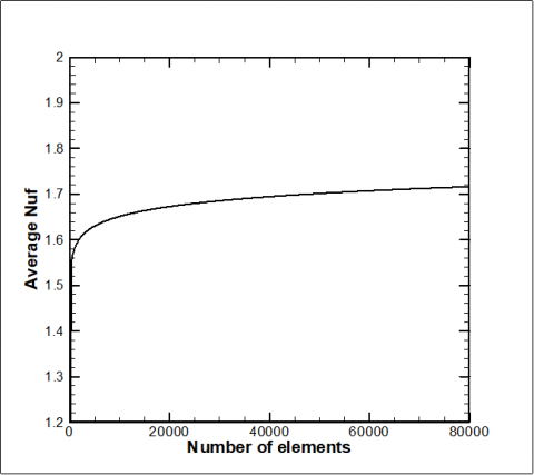
Figure 2. Mesh Independence study for average Nusselt Number for the fluid phase
The accuracy of the CFD numerical procedure is an important issue; thus, the 2D domain for a square porous enclosure was tested. To evaluate the elements numbers required, various meshes were tested. The tests were carried out in the by adopting different grid distributions such as extremely coarse, coarse, normal, fine, finer, extra fine and extremely fine. The mesh independence test proved that the finer type of mesh gave an acceptable solution. It was shown that increasing the number of cells further gives less than 0.04% variation in Nusselt number value (Figure 2).
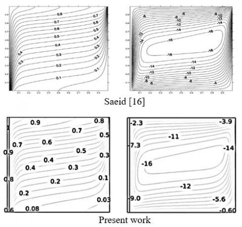
To assess the validity of this solver, the obtained results were compared with the results computed by Saeid [16] for streamline and isotherm contours at (Ra = 1000, Kr = 1 and D = 0.02). The comparison has shown an acceptable agreement between the two sets of results as shown in Figure 3. In addition, Table 1 shows a great match in Nusselt number between previous results with the present results.
Table 1. Validation of Nusselt number with previous researchers
|
Author |
Ra = 10 |
Ra = 100 |
|
Beckermann et al [29] |
No data |
3.11 |
|
Moya et al [30] |
1.07 |
2.80 |
|
Nithiarasu et al [31] |
1.08 |
3.02 |
|
Al-Farhany and A. Turan [32] |
1.08 |
3.13 |
|
Sameh et al [25] |
1.09 |
3.01 |
|
Present Work |
1.08 |
3.12 |
Numerical analysis are presented to investigate the effect of various non-dimensional parameters such as the modified Rayleigh number (10 ≤ Ra ≤ 103), Aspect ratio (0.5 ≤ A≤ 10), dimensionless finite thickness-wall (0.02 ≤ D ≤ 0.5) and the Thermal conductivity ratio (0.1 ≤ Kr ≤ 10) and arrangement of partially active zones on the heat transfer and fluid flow for the free convection within a rectangular porous cavity. Based on the arrangement of the present study, two cases of partial heating and cooling are carried out. In the first case, the thermally active zone is referred to as Top-Bottom,while in the second case is referred to as Bottom-Top.
4.1 Effects of Modified Rayleigh number
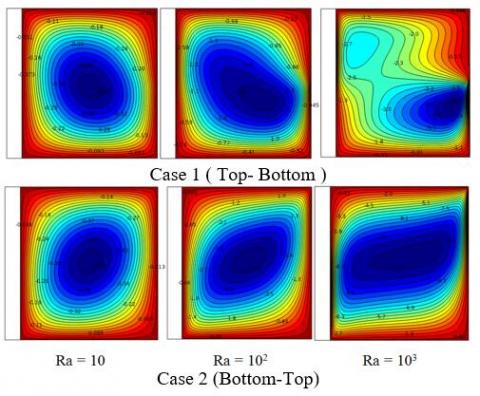
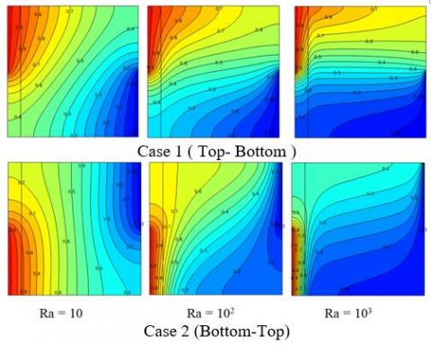
Figure 4 demonstrates the fluid flow and the isotherms behaviour for various dimensionless Rayleigh number for two cases of thermally active wall locations and [D = 0.1, Kr = 1, (A = 1)]. The streamlines show that the strength of circulation inside the porous enclosure increases with increasing the modified Rayleigh number for both cases. For example, stream function increased from $|\psi|_{\max }=1.8073$ at Ra = 100 to $|\psi|_{\max }=4.7922$ at Ra = 103. The reason behind that is that as the modified Rayleigh number increases, the intensity of the fluid flow circulation will increase because of the buoyancy force and natural convection that become very strong leading to an increase of the stream function. Also, it may be noted from the streamlines contours that the location of the thermally active zones have an influence on the stream function value. For example, the stream function value for case one was $|\psi|_{\max }=4.7922$ while for case 2 it was $|\psi|_{\max }=12$. Accordingly, the heat transfer rate resulting from case two will be higher than that of case one. The reason behind that is the two inner vortexes which are created in the middle of the enclosure and reduced the rate of heat transfer. The wall location also has great influence on the isotherm contour, where it is not curved too much in the middle of the enclosure at Ra = 103 for case 1, while for case 2 it is significantly curved which enhanced the rate of heat transfer as in Figure 5.
Figure 4. Streamlines of various dimensionless Rayleigh number for case 1 and case 2
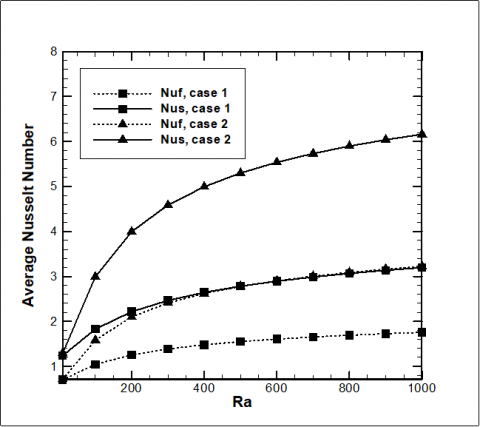
Figure 6 shows the effect of the thermally active wall location on the rate of heat transfer. It can be seen that the average Nusselt number for case 1 is higher than that corresponding of case 2. It can be also noted that for each case of thermally active wall, the average Nusselt number for the fluid phase and along the hot wall increase as the Rayleigh number increases. For example, for case 1, when the Rayleigh number increased from Ra = 10 to Ra = 103, the average Nusselt number for the fluid phase increased from $\overline{N u_{f}}=0.7047$ to $\overline{N u_{f}}=1.7573$. Similarly, $\overline{N u_{w}}=1.2388$ at Ra = 10 while $\overline{N u_{w}}=3.1958$ at Ra = 103. This increase in the rate of heat transfer also observed for case 2 but in a higher rate compared to case 1.
Figure 5. Isotherms contour for various dimensionless Rayleigh number for case 1 and case 2
Figure 6. Average Nusselt number for fluid phase and along solid hot wall variation with Rayleigh number for cases 1&2
4.2 Effect of dimensionless wall thickness
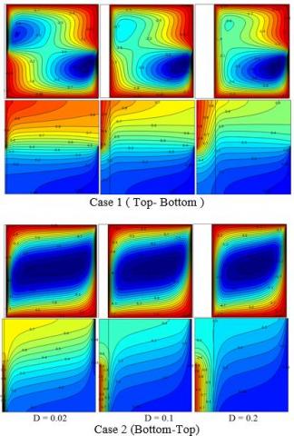
Figure 7 illustrates the influence of dimensionless finite wall thickness on the streamlines and isotherms for the two cases of thermally active wall locations at the modified Rayleigh number (Ra = 103), thermal conductivity ratio (Kr = 1), Aspect ratio (A = 1)]. The heat conduction mode is dominated with the increasing of the dimensionless walls thickness. The figure shows that increasing the wall thickness reduced the intensity of the fluid flow due to the reduction of the convection heat transfer. It was noticed that $|\psi|_{\max }=5.1$ and 4.4 at $\mathrm{D}=0.02$ and 0.2, respectively. The thermally active zone is still having a great influence on the heat transfer rate for various dimensionless walls thicknesses. It may be noted that when Ra = 103, Kr = 1, D = 0.02, A = 1 for case one, the $|\psi|_{\max }=5.1$ while $|\psi|_{\max }=16$ for case two. Those results indicated that case two gave higher heat transfer rate from case one.
Dual clockwise rotating cells are observed at all different wall thickness ratios for case one, while the inner cells disappeared at all wall thickness ratios for the case two of the thermally active wall. The corresponding isotherm shows that the strong thermal boundary is formed at the thin wall of the thermally active porous enclosure.
These remarks are the same for the corresponding case one but in fewer manners due to formation of dual inner cells reduced the heat transfer rate as a second parameter in addition to the increasing of finite wall thickness.
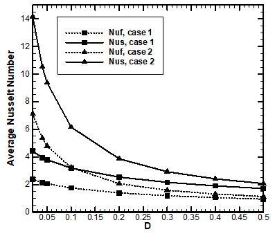
The effect of dimensionless wall thickness for various walls location of average Nusselt numbers for both the fluid phase and along the hot wall is discussed in Figure 6. For example, when the wall thickness increased from D = 0.02 to D = 0.2, Nusselt number for the fluid phase and along the hot wall decreased from $\overline{N u_{f}}=2.3851$ to $\overline{N u_{f}}=1.4027$ and from $\overline{N u_{w}}=4.4244$ to $\overline{N u_{w}}=3.1958$ respectively. Figure 8 shows the average Nusselt number for various dimensionless finite wall thicknesses. It can be clearly seen that the Nus and Nuf are decreasing with increasing the dimensionless finite wall thickness (D). It can be noted that for each case of thermally active wall that the average Nusselt number for the fluid phase and along the hot wall as the dimensionless finite wall thickness increases.
4.3 Effect of thermal conductivity ratio
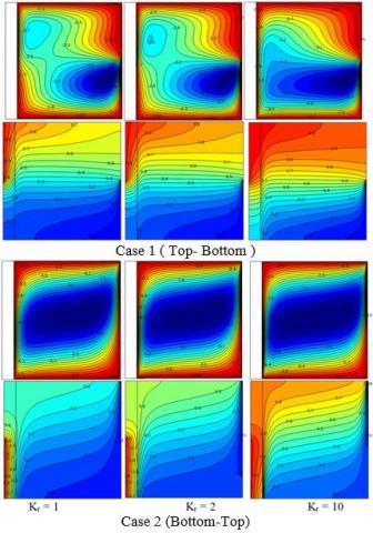
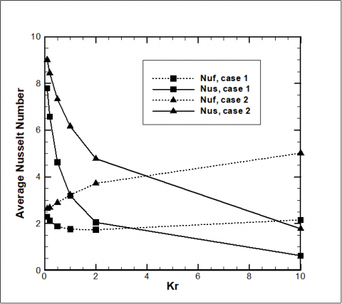
Figure 9 shows the influence of thermal conductivity ratio on the streamlines and isotherms for two cases of thermally active wall locations at the modified Rayleigh number [Ra = 103, D = 0.1, A = 1]. An increase in the the flow circulation inside the enclosure has been observed after increasing the thermal conductivity. This is noted from the stream function value from $|\psi|_{\max }=4.7$ at Kr = 1 to $|\psi|_{\max }=7.2$ at Kr = 10 due to the reduction in the solid walls resistance as the thermal conductivity ratio values increased. Accordingly, the convection effects in the fluid increased when the values of (Kr) increased. Therefore, it is concluded that the natural convection increases by icreasing the (Kr) values. The main concern of the present work is to examine the effect of active walls location on the heat transfer rate; so that it can be noted from the stream function values $|\psi|_{\max }=4.7$ for case 1 while $|\psi|_{\max }=12$ for case two under Ra = 103, D = 0.1, Kr = 1, A = 1. The effect of thermaly active zones on the average nyussel number are illustrated in Figure 10. Thermal conductivity ratio is defined as the ratio of solid wall thermal conductivity to the fluid thermal conductivity. Thus, based on this defination it was observed that the lower the thermal conductivity ratio, the higher the average Nusselt number along the wall and the lower of average Nusselt number for the fluid phase. This phenomenon is valid for case 2. For example average Nusselt number along the solid hot wall decreased from at Kr = 1 to at Kr = 10. On the other hand, Nusselt number for the fluid phase decreased from $\overline{N u_{w}}=6.1605$ at $\mathrm{K}_{\mathrm{r}}=1$ to $\overline{\mathrm{N} u_{w}}=1.7747$ at $\mathrm{K}_{\mathrm{r}}=10$ at Kr =1 to $\overline{N u_{f}}=5.0148$. The behaviour for average Nusselt number along the solid wall for case 1is similar to that for case 2, where it decreases with increasing the thermal conductivity ratio. The average Nusselt number along the fluid phase is decreasing as thermal conductivity ratio increases due to formation of two inner circulation which reduces the rate of heat transfer. Further increase in the thermal conductivity ratio will eliminated the two inner circles and caused the average Nusselt number for the fluid phase to slightly increase.
Figure 7. Streamlines and isotherms for various finite thickness wall ratio for Top-bottom and Bottom-top
Figure 8. Average Nusselt number for fluid phase and along solid hot wall variation with finite wall thickness for cases 1&2
Figure 9. Streamlines and isotherms for various thermal conductivity ratio for Top-bottom and Bottom-top
Figure 10. Average Nusselt number for fluid phase and along solid hot wall variation with thermal conductivity ratio for cases 1&2
4.4 Effect of aspect ratio
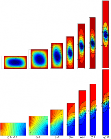
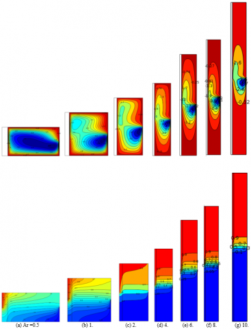
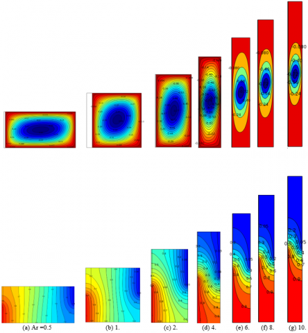
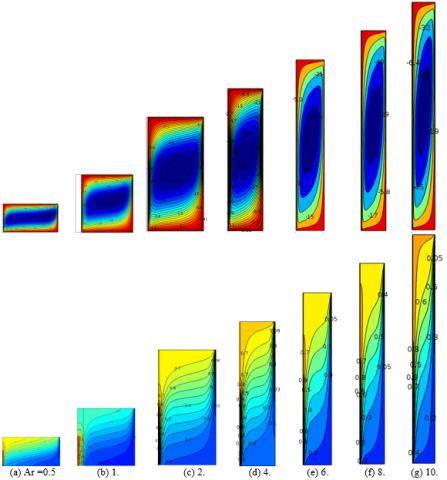
Figures (11-14) demonstrate the effect of aspect ratio on the flow pattern and isotherms contours for different Ra number [Ra = 10, Ra = 103] and different thermally active walls locations at dimensionless finite wall thickness D = 0.1, Kr = 1. It can be seen that a single rotating cell is formed for all aspect ratios for each case of the thermally active walls when the Ra = 10. In addition, increasing Rayleigh number to Ra = 103 leads to the formation of duel inner cells at the left lower part of the enclosure for case-1 when the aspect ratio A = 0.5. further increase of aspect ratio leads to the formation of two inner cells at the right upper and left lower parts of the enclosure. While for case two, only inner circle formed in the enclosure which makes the heat transfer rate is still better for case two under various aspect ratios. The isotherm indicates that the temperature is distributed well in the enclosure for all aspect ratios. It can be noted form the isotherm contour that the heat transfer rate is enhanced in case two (Bottom-Top) of the thermally active location as the isotherms lines in case two are more curved which is an indicator that the heat transfer rate is improved.
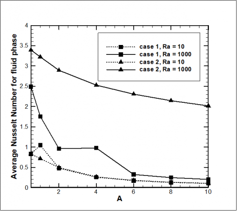
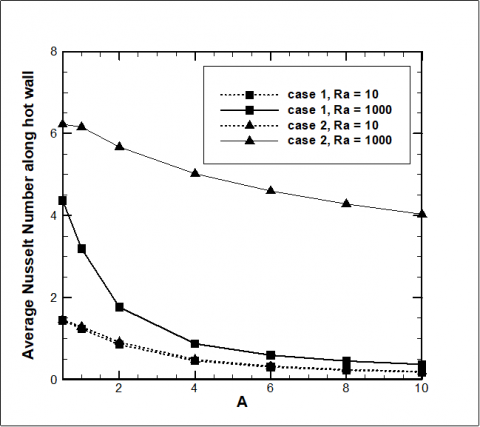
The effects of the aspect ratio and partially thermal active wall on the Nusselt number for fluid phase and along the solid hot wall are presented in Figures 15 and 16 respectively. As the aspect ratio increases, the Nusselt number for the fluid phase decreases. However Nusselt number for the fluid phase at case 1 and Ra = 10 increases when aspect ratio increase from A = 0.5 to A = 1 and then still decreasing as the aspect ratio increases. Nusselt number along the hot solid wall still decreases as the aspect ratio increases.
The present work presented the numerical simulations of natural convection heat transfer in a partially heated porous enclosure with finite wall thickness from the left hand side using finite element method. The present work is validated with significant researchers and the main drawing conclusions can be summarized as follow:
Increasing of thermal conductivity ratio leads to increase of Nusselt number of the fluid phase and decreases the Nusselt number along the hot solid wall for case 2. However the location of thermally active wall has significant on this fact because of circulation formation will reduce the average Nusselt number for the fluid phase till thermal conductivity ratio increases to Kr = 2 where Nusselt number for the fluid phase starts to increase.
Figure 11. Streamlines (up) and isotherms (down) of the Top-Bottom heating wall locations for various aspect ratio with Ra = 10, D = 0.1, Kr = 1
Figure 12. streamlines (up) and isotherms (down) of the Top-Bottom heating wall locations for various aspect ratio with Ra = 103, D = 0.1, Kr = 1
Figure 13. streamlines (up) and isotherms (down) of the Bottom-Top heating wall locations for various aspect ratio with Ra = 10, D = 0.1, Kr = 1
Figure 14. streamlines (up) and isotherms (down) of the Bottom-Top heating wall locations for various aspect ratio with Ra = 103, D = 0.1, Kr = 1
Figure 15. Average Nusselt number for the fluid phase variation with the aspect ratio for case1 and case2 under different Rayleigh number
Figure 16. Average Nusselt number along the solid hot wall variation with the aspect ratio for case1 and case2 under different Rayleigh number
|
A |
aspect ratio |
|
d |
dimensional wall thickness m−1 |
|
D |
non-dimensional wall thickness |
|
Da |
Darcy number |
|
g |
gravitational acceleration, m s-2 |
|
H |
high of the enclosure, m |
|
K |
permeability of the porous medium, m2 |
|
k |
thermal conductivity, W m−1 K−1 |
|
kr |
thermal conductivity ratio, kr = kw/kf |
|
L |
length of the enclosure, m |
|
Nu |
Nusselt number |
|
p |
pressure, kg m-1 s-2 |
|
P |
non-dimensional pressure |
|
Pr |
Prandtl number |
|
Ra |
modified Rayleigh number for porous medium |
|
t |
time, s |
|
T |
non-dimensional temperature |
|
$\overline{T}$ |
dimensional temperature, K |
|
u |
velocity components in x-direction, m s-1 |
|
v |
velocity components in y-direction, m s-1 |
|
x |
x coordinates, m |
|
y |
y coordinates, m |
|
U |
non-dimensional velocity components in X-direction |
|
V |
non-dimensional velocity components in Y-direction |
|
X |
non-dimensional X-coordinates |
|
Y |
non-dimensional Y-coordinates |
|
Greek symbols |
|
|
α |
effective thermal diffusivity , m2 s−1 |
|
βT |
coefficient of thermal expansion , K−1 |
|
n |
kinematic viscosity , m2 s−1 |
|
ρ |
density, kg m-3 |
|
Subscripts |
|
|
c |
cold |
|
eff |
effective |
|
f |
fluid |
|
h |
hot |
|
w |
wall |
[1] Nithiarasu P, Seetharamu KN, Sundararajan T. (1997). Non-Darcy double-diffusive natural convection in axisymmetric fluid saturated porous cavities. Heat and Mass Transfer/Waerme- und Stoffuebertragung 32(6): 427-433. https://doi.org/10.1007/s002310050141
[2] Basak T. (2006). Natural convection in a square cavity filled with a porous medium: Effects of various thermal boundary conditions. International Journal of Heat and Mass Transfer 49(7-8): 1430-1441. https://doi.org/10.1016/j.ijheatmasstransfer.2005.09.018
[3] Oztop HF. (2007). Natural convection in partially cooled and inclined porous rectangular enclosures. International Journal of Thermal Sciences 46(2): 149-156. https://doi.org/10.1016/j.ijthermalsci.2006.04.009
[4] Sathiyamoorthy M. (2007). Steady natural convection flow in a square cavity filled with a porous medium for linearly heated side wall(s). International Journal of Heat and Mass Transfer 50(9-10): 1892-1901. https://doi.org/10.1016/j.ijheatmasstransfer.2006.10.010
[5] Saha SC, Molla M, Khan M. (2012). Natural convection flow in a porous enclosure with localized heating from below. JP Journal of Heat and Mass Transfer 6(1): 1-16.
[6] Saleh H, Hashim I. (2013). Non-Darcy and localized heating effects on Benard convection in porous enclosure. Journal of Porous Media 16(1). https://doi.org/10.1615/JPorMedia.v16.i1.10
[7] Sankar M, Jang B, Do Y. (2014). Numerical study of non-Darcy natural convection from two discrete heat sources in a vertical annulus. Journal of Porous Media 17(5). https://doi.org/10.1615/JPorMedia.v17.i5.10
[8] Hossain MA, Wilson M. (2002). Natural convection flow in a fluid-saturated porous medium enclosed by non-isothermal walls with heat generation. International Journal of Thermal Sciences 41(5): 447-454. https://doi.org/10.1016/S1290-0729(02)01337-6
[9] Al-Farhany K, Abdulkadhim A. (2018). Numerical simulation for conjugate natural convection in a partially heated rectangular porous cavity. Journal of Engineering and Applied Sciences 13(16): 6823-6832. https://doi.org/10.3923/jeasci.2018.6823.6832
[10] Al-Farhany K, Abdulkadhim A. (2018). Numerical investigation of conjugate natural convection heat transfer in a square porous cavity heated partially from left sidewall. International Journal of Heat and Technology 36(1): 237-244. https://doi.org/10.18280/ijht.360132
[11] Nield DA, Bejan A. (2013). Convection in Porous Media [electronic resource]. Third Edition. ed. 2013, New York, NY: Springer Science+Business Media, Inc. digital. https://doi.org/10.1007/978-1-4614-5541-7
[12] Mbaye M, Bilgen E, Vasseur P. (1993). Natural-convection heat transfer in an inclined porous layer boarded by a finite-thickness wall. International Journal of Heat and Fluid Flow 14(3): 284-291. https://doi.org/10.1016/0142-727X(93)90060-Z
[13] Baytaş AC. (2001). Conjugate natural convection in a square porous cavity. Heat and Mass Transfer 37(4): 467-473. https://doi.org/10.1007/PL00013297
[14] Chang WJ, Lin HC. (1994). Natural convection in a finite wall rectangular cavity filled with an anisotropic porous medium. International Journal of Heat and Mass Transfer 37(2): 303-312. https://doi.org/10.1016/0017-9310(94)90101-5
[15] Mahdy A, Chamkha A, Baba Y. (2010). Double-diffusive convection with variable viscosity from a vertical truncated cone in porous media in the presence of magnetic field and radiation effects. Computers & Mathematics with Applications 59(12): 3867-3878. https://doi.org/10.1016/j.camwa.2010.04.024
[16] Saeid NH. (2007). Conjugate natural convection in a porous enclosure: effect of conduction in one of the vertical walls. International Journal of Thermal Sciences 46(6): 531-539. https://doi.org/10.1016/j.ijthermalsci.2006.08.003
[17] Al-Amiri A, Khanafer K, Pop I. (2008). Steady-state conjugate natural convection in a fluid-saturated porous cavity. International Journal of Heat and Mass Transfer 51(17-18): 4260-4275. https://doi.org/10.1016/j.ijheatmasstransfer.2007.12.026
[18] Saleh H, Hashim I. (2012). Conjugate natural convection in a porous enclosure with non-uniform heat generation. Transport in Porous Media 94(3): 759-774. https://doi.org/10.1007/s11242-012-0023-z
[19] Saravanan S, Brinda RK. (2018). Thermal nonequilibrium porous convection in a heat generating medium. International Journal of Mechanical Sciences 135: 133-145. https://doi.org/10.1016/j.ijmecsci.2017.10.024
[20] Saleh H. (2011). Effect of conduction in bottom wall on darcy–bénard convection in a porous enclosure. Transport in Porous Media 88(3): 357-368. https://doi.org/10.1007/s11242-011-9743-8
[21] Revnic C. (2009). Free convection in a square cavity filled with a bidisperse porous medium. International Journal of Thermal Sciences 48(10): 1876-1883. https://doi.org/10.1016/j.ijthermalsci.2009.02.016
[22] Bhuvaneswari M, Sivasankaran S, Kim YJ. (2011). Effect of aspect ratio on convection in a porous enclosure with partially active thermal walls. Computers & Mathematics with Applications 62(10): 3844-3856. https://doi.org/10.1016/j.camwa.2011.09.033
[23] Roslan R, Saleh H, Hashim I. (2014). Natural convection in a differentially heated square enclosure with a solid polygon. The Scientific World Journal 2014: 11. https://doi.org/10.1016/j.camwa.2011.09.033
[24] Mahapatra PS, Manna NK, Ghosh K. (2015). Effect of active wall location in a partially heated enclosure. International Communications in Heat and Mass Transfer 61: 69-77. https://doi.org/10.1016/j.icheatmasstransfer.2014.12.019
[25] Ahmed SE. (2016). Conjugate natural convection in an inclined square porous enclosure with finite wall thickness and partially heated from its left sidewall. Heat Transfer Research 47(4): 383-402. https://doi.org/10.1615/HeatTransRes.2016007964
[26] Al-Rashed AA. (2017). Numerical study of three-dimensional natural convection and entropy generation in a cubical cavity with partially active vertical walls. Case Studies in Thermal Engineering 10: 100-110. https://doi.org/10.1016/j.csite.2017.05.003
[27] Abdulkadhim A, Abed A, Al-Farhany K. (2018). Computational investigation of conjugate heat transfer in cavity filled with saturated porous media. Frontiers in Heat and Mass Transfer (FHMT) 11. https://doi.org/10.5098/hmt.11.12
[28] Das D, Roy M, Basak T. (2017). Studies on natural convection within enclosures of various (non-square) shapes–A review. International Journal of Heat and Mass Transfer 106: 356-406. https://doi.org/10.1016/j.ijheatmasstransfer.2016.08.034
[29] Beckermann C, Viskanta R, Ramadhyani S. (1986). A numerical study of non-darcian natural convection in a vertical enclosure filled with a porous medium. Numerical Heat Transfer 10(6): 557-570. https://doi.org/10.1080/10407788608913535
[30] Moya SL, Ramos E, Sen M. (1987). Numerical study of natural convection in a tilted rectangular porous material. International Journal of Heat and Mass Transfer 30(4): 741-756. https://doi.org/10.1016/0017-9310(87)90204-3
[31] Nithiarasu P, Seetharamu KN, Sundararajan T. (1996). Double-diffusive natural convection in an enclosure filled with fluid-saturated porous medium: A generalized non-Darcy approach. Numerical Heat Transfer; Part A: Applications 30(4): 413-426. https://doi.org/10.1080/10407789608913848
[32] Al-Farhany, K, Turan A. (2011). Non-Darcy effects on conjugate double-diffusive natural convection in a variable porous layer sandwiched by finite thickness walls. International Journal of Heat and Mass Transfer 54(13-14): 2868-2879. https://doi.org/10.1016/j.ijheatmasstransfer.2011.03.012