S. Mabrak | S. Chakroune* | D. Khodja
OPEN ACCESS
In this paper, first of all the motor performance created by permanent magnetic in a slot less air-gap of a surface mounted permanent-magnet synchronous motor with non magnetic rotor and either sinusoidal or mixed (quasi-Halbatch) magnetization using polar coordinates is presented. After that the analysis works for both internal and external rotor motor topologies, the effect of stator slots is introduced by modulating the magnetic field distribution in the less slot stator by the complex relative air-gap permeances and the conformal transformation of the slot geometry. Finally, the predicted results of flux density distribution and cogging torque with those obtained by finite-element are analyzed.
magnetic field, permanent-magnet, air-cored, finite element, cogging torque
Whatever motor or generator mode, synchronous machines with permanent magnets have become more attractive because they meet the requirements of new technologies. The renewed interest for these machines is due in large part to their excellent dynamic characteristics, their low losses and their high mass torque, which makes them better suited to industrial applications with electric drives requiring position or speed controls. Indeed, the advent of magnets has not only increased the energy density of these machines, but also reduces their size and their losses. In addition, the permanent magnet excitation has allowed these machines to operate without collector and without brushes and, thus increasing their lifetime service while reducing the maintenance cost. Although enormous progress has been made in their field, these machines continue to be studied in performance terms, cost and reliability [1].
Nowadays, Permanent magnet synchronous motors (PMSM) are widely used in many industrial applications for their compactness and their high efficiency, the main focus at this point will be PM motors with surface-mounted magnets and sinusoidal or mixed magnetization. The analytical model could account the air-gap flux density waveform. However, it only provided field solutions at the stator and rotor surfaces, which is usually insufficient for accurately predicting the performance of less slot motor topologies [1, 2].
This paper presents the analytical and numerical models for predicting the magnetic field distribution in air-cored internal and external field machines. The proposed method for air-gap field calculation has been used to get the expressions for back EMF and cogging torque waveforms. Knowing that, electrical motors use mainly rare-earth permanent magnets, these materials are characterized by a large hysteresis cycle and have a high coercive magnetic field Hc [1, 3]. The field and cogging torque characteristics are quite sensitive to rotor and stator geometry due to the small air-gap [3]. Item that can be made known in this article.
The magnetization $\overrightarrow{\mathrm{M}}$ of PM can be assumed constant for a given temperature if the relative permeability is assumed equal to 1. Therefore, the characteristic of the magnet is approximated by a straight line in the B-H plane and the flux density inside the PM is equal to:
$\vec{B}=\vec{B}_{r}+\mu_{0} \mu_{r p m} \vec{H}_{0}$ (1)
where, $B_{r}$ is the remanent induction of the PM and μrpm its relative permeability.
The analytical models regroup explicit equations, which have the particularity to conserve an analytical expression after their resolution, (i.e.) that all model parameters can be written as a function of the other parameters. Many works have used the analytical model for the magnetic rotor. In the developed analytical method presented in this paper, the field distribution is obtained by solving equations in polar coordinate system and assuming a non magnetic rotor [3].
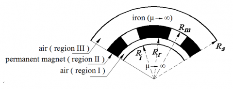
The stator slots and the non magnetic cylindrical rotor and stator core, as shown in Figure 1. In this paper, only the final solution is given in the form of an infinite Fourier series. A pole internal or external rotor PM motor and sinusoidal or mixed magnetization are shown in Figure 2; the conductivity of all regions is assumed to be zero.
Figure 1. General analytical model for field calculation
Figure 2. Sinusoidal and mixed magnetization
In the study, the magnet bars number is considered to be sufficient to get a sinusoidal or mixed magnetization. The magnet lies within an annular region and its magnetization vector is:
$\vec{M}=M_{r} \hat{r}+M_{\theta}$ (2)
Such as $M_{r}$ and $M_{\theta}$ are defined by:
$M_{r}(r, \theta)=\sum_{1,3,5, \ldots}^{\infty} M_{r n} \cos (n p \theta)$ (3)
$M_{\theta}(r, \theta)=\sum_{1,3,5, \ldots}^{\infty} M_{\theta n} \sin (n p \theta)$ (4)
where $p$ is the pairs pole number and $n$ is the harmonic number.
For sinusoidal magnetization:
$M_{r n}=\frac{4 B_{r} \alpha_{p} \cos \left(n p \frac{\pi}{2} \alpha_{p}\right)}{\pi\left(n \alpha_{p}\right)^{2}-1}$ (5)
$M_{\theta n}=\pm \frac{4 n B_{r} \alpha_{p}^{2} \cos \left(n p \frac{\pi}{2} \alpha_{p}\right)}{\pi\left(n \alpha_{p}\right)^{2}-1}$ (6)
if $n \alpha_{p}=1: M_{r n}=-M_{\theta n}=\pm \frac{B_{r}}{n}$ (7)
For the mixed magnetization:
$M_{r n}=\frac{4 B_{r} \sin \left(n p \frac{\pi}{2} \alpha_{r}\right)}{\pi n}$ (8)
$M_{\theta n}=\pm \frac{4 M \cos \left(\left((1-a) \alpha_{r}+a\right) \frac{\pi n}{2}\right)}{\pi n}$ (9)
where, $\alpha_{r}$ is the radial magnet arc to pole-pitch ratio.
(-) is for an internal rotor machine (external field), (+) is for an external rotor machine (internal field).
The magnetic field produced by a magnetized magnet machine can be described by the scalar magnetic potential $\varphi$ [2, 4]:
$\Delta \varphi_{I}=\frac{\partial^{2} \varphi_{I}}{\partial r^{2}}+\frac{1}{r} \frac{\partial \varphi_{I}}{\partial r}+\frac{1}{r^{2}} \frac{\partial^{2} \varphi_{I}}{\partial \theta^{2}}=0$ (10)
$\Delta \varphi_{I I}=\frac{\partial^{2} \varphi_{I I}}{\partial r^{2}}+\frac{1}{r} \frac{\partial \varphi_{I I}}{\partial r}+\frac{1}{r^{2}} \frac{\partial^{2} \varphi_{I I}}{\partial \theta^{2}}=\frac{d i v \vec{M}}{\mu_{r}}$ (11)
$\Delta \varphi_{I I I}=\frac{\partial^{2} \varphi_{I I I}}{\partial r^{2}}+\frac{1}{r} \frac{\partial \varphi_{I I I}}{\partial r}+\frac{1}{r^{2}} \frac{\partial^{2} \varphi_{I I I}}{\partial \theta^{2}}=0$ (12)
$\quad d i v \vec{M}=\frac{M_{r}}{r}+\frac{\partial M_{r}}{\partial r}+\frac{1}{r} \frac{\partial M_{\theta}}{\partial \theta}$ (13)
For both internal and external rotor machines, the general solutions governing (10) and (13) are obtained as:
$\varphi_{I}(r, \theta)=\left(C_{1} r^{n p}+C_{2} r^{-n p}\right) \cos (n p \theta)$ (14)
$\varphi_{I I}(r, \theta)=\left(C_{3} r^{n p}+C_{4} r^{-n p}+K_{n}\right) \cos (n p \theta)$ (15)
$\varphi_{I I I}(r, \theta)=\left(C_{5} r^{n p}+C_{6} r^{-n p}\right) \cos (n p \theta)$ (16)
where,
$K_{n}=-\frac{M_{r n}+n p M_{\theta n}}{n p^{2}-1} r$ (17)
The constants $\mathrm{C}_{1}, \mathrm{C}_{2}, \mathrm{C}_{3}, \mathrm{C}_{4}, \mathrm{C}_{5}, \mathrm{C}_{6}$ are determined from the boundary conditions as:
$r=R_{i}: H_{\theta I}=0$ (18)
$r=R_{m}: B_{r I}=B_{r I I}, H_{\theta I}=H_{\theta I I}$ (19)
$r=R_{r}: B_{r I I}=B_{r I I I}, H_{\theta I I}=H_{\theta I I I}$ (20)
$r=R_{s}: H_{\theta I I I}=0$ (21)
In the air space region I, the magnetic field can be expressed as:
Hence, the complete solution for the magnetic field components in the airspace/magnet regions can be deduced from the general solution of Laplacian/quasi Poissonian equations and the specified boundary conditions.
(1) Where, when np≠1:
For an air-cored external rotor machine; $\mathrm{R}_{\mathrm{s}} \rightarrow \infty$
$C_{2}=\frac{\left(M_{r n}+M_{t n}\right)\left(R_{m}^{-n p+1}-R_{r}^{-n p+1}\right)}{2(n p-1)}$ (22)
$C_{1}=R_{r}^{2 n p} C_{2}$ (23)
$B_{r I}(r, \theta)=\sum_{1,3,5, r}^{\infty} \frac{C_{2}}{r}\left(R_{i}^{2 n p} r^{n p}+r^{-n p}\right) \cos (n p \theta)$ (24)
$B_{\theta I}(r, \theta)=\sum_{1,3,5, \ldots}^{\infty} \frac{C_{2}}{r}\left(R_{i}^{2 n p} r^{n p}-r^{-n p}\right) \sin (n p \theta)$ (25)
where,
(2) Where, when np=1:
$B_{r I}(r, \theta)=K_{0}\left(R_{i}^{2} r^{-2}+1\right) \cos (n p \theta)$ (26)
$B_{\theta I}(r, \theta)=K_{0}\left(R_{i}^{2} r^{-2}-1\right) \sin (n p \theta)$ (27)
$K_{0}=\frac{\left(M_{r n}+M_{t n}\right)\left(\log \left(R_{m}\right)-\log \left(R_{r}\right)\right)}{2}$
For an air-cored internal rotor machine, i.e., $\mathrm{R}_{\mathrm{i}} \rightarrow 0$
$C_{2}=\frac{\left(M_{r n}-M_{t n}\right)\left(R_{m}^{-n p+1}-R_{r}^{-n p+1}\right)}{2(n p+1)}$ (28)
$C_{1}=R_{s}^{2 n p} C_{2}$ (29)
$B_{r I}(r, \theta)=\sum_{1,3, \ldots}^{\infty} \frac{C_{2}}{r}\left(R_{s}^{2 n p} r^{n p}+r^{-n p}\right) \cos (n p \theta)$ (30)
$B_{\theta I}(r, \theta)=\sum_{1,3, \ldots}^{\infty} \frac{c_{2}}{r}\left(R_{s}^{2 n p} r^{n p}-r^{-n p}\right) \sin (n p \theta)$ (31)
The field distribution in the middle of the air gap at $r=R_{r}+\frac{g}{2}$ for 12 poles external rotor of a surface PM motor with parameters given in Table 1, has been calculated using (24) and (25).
Table 1. Parameters of the 36-Slot, 12-Pole Surface PM Motor
|
Parameter |
Symbols and values |
|
Pole number |
$2 p=12$ |
|
Slot number |
$Q_{s}=36$ |
|
Magnet-arc to pole-pitch ratio |
$\alpha_{p}=3 / 3$ |
|
Air-gap length |
$\mathrm{g}=0.8 \mathrm{mm}$ |
|
Magnet radial thickness |
$l_{m}=6.7 \mathrm{mm}$ |
|
Slot opening width |
$b_{o}=2.5 \mathrm{mm}$ |
|
Rotor surface radius |
$R_{r}=73.8 \mathrm{mm}$ |
|
Magnet surface radius |
$R_{m}=80.5 \mathrm{mm}$ |
|
Stator outer radius |
$R_{o}=97.5 \mathrm{mm}$ |
|
Stack length |
$L_{a}=40.0 \mathrm{mm}$ |
|
Magnet remanence |
$B_{r}=0.8 \mathrm{T}$ |
Figure 3. Analytically and finite-element predicted field distributions, for 12-pole, less slot, air-cored, external rotor sinusoidal magnetized magnet machine
Figure 4. Comparison of analytically and finite-element predicted field distributions, for 12-pole, less slot, air-cored, external rotor mixed magnetized magnet machine
The overlaid plots of the analytical and numerical field solutions for one pole pitch are shown in Figures 3 and 4.
Through the results of the previous figure, we can declare that an excellent agreement is achieved between analytical and finite-element predictions for external rotor machines. The same remark for the mixed magnetized results witch illustrated in the following figure.
The presence of slots in the motor, affects the flux distribution in the air gap and in the magnets. The complex relative air-gap permeance is obtained by transforming the actual slotted air-gap into a less slot air-gap using four conformal transformations. Conformal transformation or conformal mapping is the representation of a bounded area in the plane of another complex variable [4, 5]. The method presented in this paper and developed by Zarko.
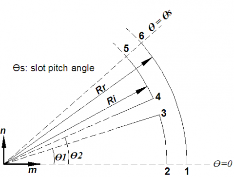
The basic principle of the method will be explained on the example of an infinitely deep slot opening shown in Figure 5.
Figure 5. Slot opening in the S plane
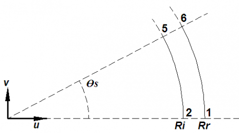
And the K plane contains the less slot air-gap (Figure 6), while Z, W and T planes are used for intermediate transformations.
Figure 6. Slot opening in the K plane (less slot air-gap)
The link between flux density in the S and K planes is given by:
$B_{s}=B_{k}\left(\frac{\partial \mathrm{k}}{\partial \mathrm{s}}\right)^{*}$ (32)
where,
$\frac{\partial \mathrm{k}}{\partial \mathrm{s}}=\frac{\mathrm{k}}{\mathrm{s}} \frac{(\omega-1)}{(\omega-\mathrm{a})^{\frac{1}{2}(\omega-\mathrm{b})^{\frac{1}{2}}}}$ (33)
$B_{s}=B_{k}\left[\frac{k}{s} \frac{(\omega-1)}{(\omega-a)^{\frac{1}{2}}(\omega-b)^{\frac{1}{2}}}\right]$ (34)
Figure 7. Cross-section of the surface PM motor
The actual open-circuit flux density is then determined from the product of the flux density produced by the magnets in a less slot rotor and the relative air gap permeance $\lambda(r, \theta)$:
$B_{s}(r, \theta)=B_{\text {slotless}}(r, \theta) \lambda^{*}(r, \theta)$ (35)
where,
$\lambda=\left[\frac{\mathrm{k}}{\mathrm{s}} \frac{(\omega-1)}{(\omega-\mathrm{a})^{\frac{1}{2}}(\omega-\mathrm{b})^{\frac{1}{2}}}\right]$ (36)
$k=R_{i} e^{j\left(\frac{g^{\prime}}{\pi} \ln \omega+\frac{\theta_{s}}{2}\right)}, z=\ln (s)$
with,
$s=r \mathrm{e}^{\mathrm{j} \theta}$
$z=j \frac{g^{\prime}}{\pi}\left[\ln \left|\frac{1+p}{1-p}\right|-\ln \left|\frac{b+p}{b-p}\right|-2 \frac{b-1}{\sqrt{b}} \tan ^{-1}\left(\frac{p}{\sqrt{p}}\right)\right]+C$
$p=\sqrt{\frac{\omega-b}{\omega-a}}, C=\ln R_{i}+j \theta_{2}, g^{\prime}=\ln \left(\frac{R_{i}}{R_{m}}\right)$
$b=\left[\frac{b_{0}^{\prime}}{2 g^{\prime}}+\sqrt{\frac{b_{0}^{\prime 2}}{2 g^{\prime}}+1}\right]^{2}, a=\frac{1}{b} and b_{0}^{\prime}=\theta_{2}-\theta_{1}$
Since $\lambda$ is a complex number, it can be written in the form:
$\lambda=\left[\frac{\mathrm{k}}{\mathrm{s}} \frac{(\omega-1)}{(\omega-\mathrm{a})^{\frac{1}{2}}(\omega-\mathrm{b})^{\frac{1}{2}}}\right]$ (36)
$\lambda=\lambda_{a}+i * \lambda_{b}$ (37)
With:
$\lambda_{a}(r, \theta)=\lambda_{0}(r)+\sum_{n=1}^{N_{\lambda}} \lambda_{a n}(r, \theta) \cos \left(n Q_{s} \theta\right)$ (38)
$\lambda_{b}(r, \theta)=\sum_{n=1}^{N_{\lambda}} \lambda_{b n}(r, \theta) \sin \left(n Q_{s} \theta\right)$ (39)
The field solution in the slotted air-gap can be written in the form
$B_{s}=B_{s r}+i * B_{s \theta}$ (40)
$B_{s r}=\operatorname{Re}\left(B_{k} \lambda^{*}\right)=\operatorname{Re}\left[\left(B_{r I}+j B_{\theta I}\right)\left(\lambda_{a}-j \lambda_{b}\right)\right]=B_{r I} \lambda_{a}+B_{\theta I} \lambda_{b}$ (41)
$B_{s \theta}=i m\left(B_{k} \lambda^{*}\right)=i m\left[\left(B_{r I}+j B_{\theta I}\right)\left(\lambda_{a}-j \lambda_{b}\right)\right]=B_{\theta I} \lambda_{a}-B_{r I} \lambda_{b}$ (42)
where $B_{r I}$ and $B_{\theta I}$ are the radial and tangential flux density components in the less slot air gap. $\lambda_{a}$ and $\lambda_{b}$ are the real and imaginary parts of the complex relative air gap permeances.
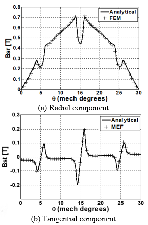
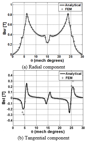
It is important to notice that, the radial component of the flux density in the slotted air gap $B_{s r}$ is a function of both the radial and tangential flux density components in the less slot air gap. The analytical field solution in the slotted air gap of a surface PM motor calculated in section II has been compared to the results of finite element simulations. The overlayer plots of the analytical and numerical field solutions for one pole pitch are shown in Figure 8 and 9.
Figure 8. Waveforms of the complex relative air-gap permeances in the middle of the air-gap of a slotted surface PM motor
Figure 9. Waveforms of the flux density in the middle of the air-gap of a slotted surface PM motor with sinusoidal magnetization
Cogging torque is due to the modulation of the air-gap flux density by the stator slots. There are three basic approaches to the analytical calculation of cogging torque. One approach is to calculate the torque as a derivative of co-energy inside the air-gap. The second approach is to integrate the lateral forces along the slot sides [6, 7]. The third approach, is to integrate the tangential component of Maxwell stress tensor along a circular contour inside the air-gap. The tangential component of the magnetic stress vector is of particular interest for torque calculations (Figure 10).
The torque equation in the integral form can then be written as:
$T_{C}=\frac{L_{u} r^{2}}{\mu_{0}} \int_{0}^{2 \pi} B_{s r}(\theta) . B_{s \theta}(\theta) d \theta$ (43)
where $\mu_{0}$ is the vacuum permeability, $L_{u}$ is the machine stack length, $r$ is the integration surface radius, $B_{s r}$ is the radial and $B_{s \theta}$ is the tangential flux density component at radius $r$.
The cogging torque is generated by the change of magnetic energy between the permanent magnet and the stator core. The cogging torque equation is given by:
$T_{C}=\frac{\partial W_{m}}{\partial A}$ (44)
$W_{m}$ is the magnetic energy and $\theta$ is the rotor angular displacement.
Figure 11 shows the variation of the calculated air-gap flux density for different pole-pairs numbers for an external rotor machine.
Figure 10. Waveforms of the flux density in the middle of the air-gap of a slotted surface PM motor with mixed magnetization
Figure 11. Peak air-gap flux density variation with pole-pairs number
Used the two - dimensional model, the cogging torque is calculated by simulating the machine behavior on no-load for different rotor positions.
The cogging torque as a function rotor position as different slot opening widths. One possible explanation is that this difference can be attributed to the approximation made earlier in which it was assumed that the transformed contour in the K plane is identical to the circular arc in the S plane from which it originated [7].
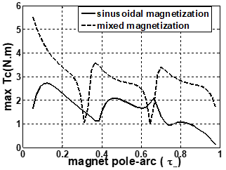
The cogging torque waveform is also affected by the width of the slot opening with ion respect to the length of the air gap. In our case, the width of the slot opening is 2.5 mm, and the total air gap length is 7.5 mm (air magnet). When the new proposed technique is applied for various magnet pole-arcs, a great reduction on cogging torque can be observed.
The analytically calculated cogging torque waveforms for the iron cored rotor machine and air cored are compared in Figure 16.
Figure 17 shows the variation of peaks cogging torque for different values of slot opening predicted with the analytical method.
We observed that, the decrease in the slot opening makes it possible to reduce the amplitude of the cogging torque.
Figure 12. Comparison of cogging torque waveforms for the 12-pole motor calculated analytically and numerically using FE method
Figure 13. Peak torque versus magnet pole - arc
Figure 14. Cogging torque as a function of number of slots per pole and phase
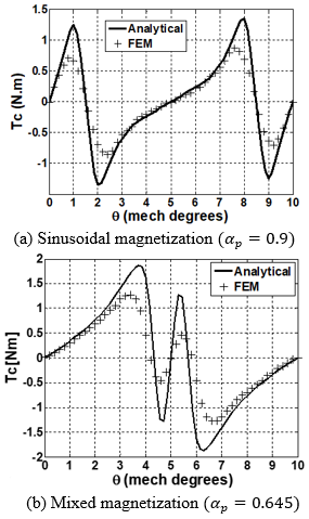
The analytically and numerically calculated cogging torque waveforms for this optimal value of $\alpha_{p}$ are compared in Figure 15.
Figure 15. Comparison of cogging torque waveforms for the 12-pole motor calculated analytically and numerically for the optimal magnet-arc to pole-pitch ratio
Figure 16. Comparison of cogging torque waveforms for the 12-pole motor calculated analytically
Figure 17. Peak torque versus slot opening
In this work, the analytical method which was developed for predicting the field distributions produced by the magnets of permanent magnet machines formed with surface-mounted magnets has been extended. The concept of complex relative air-gap permeances has been developed from conformal transformation of the slot opening and used to accurately calculate the air-gap field for both radial and tangential flux density components in the slotted air gap. In all cases studied the results of analytical calculations were in very good agreement with the results of finite-element simulations which makes this model a reliable tool for the design and analysis of surface PM motors.
[1] Diao, X.Y., Zhu, H.Q. (2017). Decoupling control of bearingless synchronous reluctance motor based on SVM inversely optimized by ACO. AMSE JOURNALS-AMSE IIETA publication-2017-Series: Modelling A, 90(2): 221-233. https://doi.org/10.18280/mmc_a.900208
[2] Boughrara, K., Chikouche, B.L., Ibtiouen, R., Zarko, D. (2009). Analytical model of slotted air-gap surface mounted permanent-magnet synchronous motor with magnet bars magnetized in shifting direction. IEEE Transactions on Magnetics, 45(2): 747-758. https://doi.org/10.1109/TMAG.2008.2008751
[3] Wang, D., Wang, X., Yang, Y., Zhang, R. (2010). Optimization of magnetic pole shifting to reduce cogging torque in solid-rotor permanent- magnet synchronous motors. IEEE Transactions on Magnetics, 46(5): 1228-1234. https://doi.org/10.1109/TMAG.2010.2044044
[4] Zarko, D., Ban, D., Lipo, T.A. (2006). Analytical calculation of magnetic field distribution in the slotted air gap of a surface permanent-magnet motor using complex relative air-gap permeance. IEEE Transactions on Magnetics, 42(7): 1828-1833. https://doi.org/10.1109/TMAG.2006.874594
[5] Zarko, D., Ban, D, Lipo, T.A. (2007). Analytical solution for cogging torque in surface permanent-magnet motors using conformal mapping. IEEE Transactions on Magnetics, 44(1): 52-65. https://doi.org/10.1109/TMAG.2007.908652
[6] Zhu, Z.Q., Howe, D. (1992). Analytical prediction of the cogging torque in radial-field permanent magnet brushless motors. IEEE Transactions on Magnetics, 28(2): 1371-1374. https://doi.org/10.1109/20.123947
[7] Kim, H.W., Kim, K.T., Jo, Y.S., Hur, J. (2013). Optimization methods of torque density for developing the neodymium free SPOKE-type BLDC motor. IEEE Transactions on Magnetics, 49(5): 2173-2176. https://doi.org/10.1109/TMAG.2013.2237890