Raghavaiah Katuri* | Srinivasarao Gorantla
© 2020 IIETA. This article is published by IIETA and is licensed under the CC BY 4.0 license (http://creativecommons.org/licenses/by/4.0/).
OPEN ACCESS
Smooth switching between energy source, leads to obtain the optimal performance of the battery and UC, which has been achieved by a novel control technique. The main objective of this work is to design a control strategy of a multiple energy storage structure (MESS) to switch the battery and ultracapacitor (UC) as per the electric vehicle (EV) requirement. To achieve the objective, a condition-based controller (CBC) has been designed by considering four math functions further those can individually be programmed according to the speed of the electric motor (EM). The speed of an EM plays a vital during switching of energy sources present in multiple energy storage structure (MESS), and the main function of designed CBC to regulate the pulse signals which is given to the switches present in the unidirectional converter (UDC) and bidirectional converter (BDC). In this work, four different controllers’ proportional-integral controller (PI), proportional integral derivative (PID) controller, the fuzzy logic controller (FLC), and artificial neural network (ANN) are used individually for generating required pulse signals to the switches present in DC-DC converters. Finally, the proposed objective can be achieved by combining CBC individually with PI, PID, FLC, ANN made a separate four hybrid controllers. Comparative analysis has been made among four hybrid controllers based on different time domain specifications. The entire circuit can be implemented with four hybrid controllers separately in MATLAB/Simulink with four cases based on the speed of the EM.
CBC, PI controller, PID controller, fuzzy logic controller, ANN controller DC-DC converters
In recent years batteries are used as a major energy source to drive the EVs. But battery-powered vehicles are suffering from conventional complications like driving range and more charging periods. To reduce the burden on batteries during peak power requirement UCs are combined with conventional energy source formed MESS and PV is used to drive the EV [1]. A dead beat related technique is adopted for MESS powered PV assisted EVs, by utilizing a novel BDC due to which, over a long-range driving of the vehicle is possible. The anticipated converter model is incorporated into the UC and battery of MESS, to eliminate the gap between the PV generation and load requirements for the PV supported EVs. To normalize the BDC operation, a dead beat related approach is recommended, which is used to maintain the appropriate power supervision between the battery and the UC [2].
In the smart city point of view, the EVs charging station plays a vital role. Sometimes, there a huge burden on the electrical distribution system due to no coordination between grid and EVs charging. To avoid the stress and acquire a better environment PV based charging stations are installed by considering optimization algorithm. Photovoltaic (PV) systems, which can reduce this stress, also show variation due to weather conditions. And the proposed method works based on the electricity cost and location of the station. The projected algorithm constitutes mainly three sections, in that the first one is, based on the price band real-time cost is obtained, the second one is finding PV power related to irradiance and to minimize the operating cost of the EV [3].
With an importance on a better ecosystem and effective operation, several experiments moved towards EVs production. The better drive range PV based EVs are modeled corresponding to the torque analysis [4]. The continuous charging of EVs from the electrical grid will mitigate the performance, which shows a burden towards per unit cost. This happens because of the open-loop set up of the whole system. To overcome, this problem, the feedback based technique is projected by considering initial operating related to the PV power available states. Due to the coordination with PV power, the performance of the system increases optimally [5]. An energy management algorithm (RTEMA) is developed by considering real-time difficulties, to provide the space for industrial and commercial applications. Here the charging place, consisting of EVs with plug and PV generating station. To know the EV arriving time and PV power different forecasting methods are derived. The foremost intentions of the developed model are to reduce the entire charging cost of EV and reducing the burden on the main grid due to extra load [6].
In the transportation system, EVs are the best replacement for IC engines based vehicles. Only battery-powered vehicles are not suitable for efficient and economical way, because battery charging and discharging periods, size of battery everything will effect on the base cost of the electric vehicle [7]. Battery/Fuel cell is one of the major driving energy sources to the electric vehicle. From starting onwards electric vehicles are suffering from driving range and also continuous charging and discharging of the battery due to starting, transient period of the vehicle. All this will affect the size of the battery that leads to increasing the size and cost of the electric vehicle. UC has been introduced to overcome cold start and to provide high power to the vehicle during the transient period. MESS will give better performance rather than a single battery [8]. The inherent character of fast charge and discharge of UC can be utilized to decrease the burden on the battery. The battery is attached at UDC end, in the same way, UC is coupled at the BDC side. During the no-load condition, UC will charge and discharges the same amount of energy with the same rate to the electric vehicle during the transient period. With this attempt, the transient power burden has been reduced on the battery [9].
Energy storage systems are having serious significance in EV, HEV, and plug-in hybrid electric automobiles [10]. From all of the power storage system, the battery is extensively utilized device. Even the battery be the primary source of the EV, numerous experiments are going on, to disclosing the momentum to search for extra results [11]. To know the status of the PV based power station an unmanned aerial vehicle is designed with an optimal control technique. The MATLAB/Simulink based characteristics are obtained, as a part of data collection. These are matched with the changed temperature power curve obtained curves. The burden on the local substation is increasing to growth in usage of EVs during changing time. To avoid the burden on the conventional power grid, PV based generation stations are installed, additionally, EV with PV also be modeled, which enhances the overall driving range of the vehicle [12]. In the present work, a new control approach is proposed to switch the battery and UC smoothly depending on the speed of the EM. Four different hybrid controllers are designed by combining CBC with ANN/FLC/PID and PI. The intended CBC and remaining controller jointly produce the pulse signal to the switches in the overall circuit depending upon the applied load on the EM.
Figure 1. Block diagram model of the projected control technique
The proposed model is mainly comprising a solar panel (SP), controllers, and converters including the EM. Here the main focused area is related to the controller’s part and which is represented with dotted lines in Figure 1. The UC is connected at BDC end whereas the battery is connected at UDC end. The CBC is placed between the output of the EM and the logical circuit. This arrangement made the proper switching signal production to the switches from the conventional controllers. Generally, the production of pulses is taking place based on the changes that appeared in the output voltages of the DC-DC converters. In this, three control switches (CS) are connected among the UDC, battery, and SP. The CS-I is connected between SP to UDC, which is used to send the power directly to the load through the converter. In between SP to the battery the CS-II connected, which is utilized to charge the battery from SP. And the CS-III is placed between battery a UDC, this is used to send energy to the load from the battery through UDC. Here the SP is used to charge the battery during sunlight available timings. The CBC is used to regulate the pulse signals generated by the conventional controller which is given to the switches present in converters. The charging and discharging modes of the battery are regulated based on the state of charge (SOC) of the battery and the output voltage of the SP.
Figure 2. The structure of the main circuit with MESS, converters, and EM
Figure 2 shows the structure of the main circuit, which mainly includes energy sources, converters, and EM. Here the battery, UDC, and SP are not connected directly to each other, and which are always connected through the CS as shown in Figure 2. The ON/OFF states of the CS decide the current flow direction in the circuit from SP to the load. Suppose, the ON condition of the CS-I allows the current flow from SP to load through UDC, in the same way, the ON state of the CS-II allows the current SP to the battery (charging) and CS-III permits the current flow from the battery to load through the converter.
The main switches (MOSFETs) present in the converters UDC and BDC are represented with S1, S2, and S3. The switch S1 belongs to UDC, whereas S2 and S3 are utilized to implement the BDC. Among three switches S1, S3 are used for boosting operation of the converters, whereas S2 is utilized for buck operation of the circuit. A total of three capacitors are used in this circuit shown in Figure 2 named C1, C2, and C3. To obtain the constant voltage required by the load, the two energy sources are connected in parallel through the converters and the final outputs are accompanying at the DC link. The main part in converters is indicated with dotted lines in the circuit which includes a capacitor, switch, and diode as shown in Figure 2. Here LBC representing the inductor connected at the battery end, in the same way, LUC shows the inductor connected at UC end.
Figure 3 illustrating the generalized model representation of the PV cell with three different circuits based on the operation. Figure 3(a) includes the one current source having current ICELL, an anti-parallel diode with current Id and output side voltage (VM), current (IM) representations. Figure 3(b) shows the MSC, in this case of operation VM becomes zero, and IM, ICELL, and ISC all are equal. Figure 3 (c) shows the ICELL value becomes zero and the output voltage is maximum that is equal to VM.
Figure 3. Represent the different stages of the PV cell (a) Complete model, (b) Model with a short circuit (MSC) (c) Model with open circuit (MOC)
From 3(a) after applying Kirchhoff’s current law (KCL) which indicates that the total cell current is splitting as a sum of the diode current and the load current attain the module current value as,
${{\operatorname{I}}_{m}}={{I}_{cell}}-{{I}_{d}}$ (1)
Diode current equation will be,
${{I}_{d}}={{I}_{rscell}}\left[ {{e}^{\left( \frac{QV}{K{{T}_{ap}}} \right)-1}} \right]$ (2)
The current-voltage resembling equation of PV cell becomes
${{I}_{m}}={{I}_{cell}}-{{I}_{rscell}}\left[ {{e}^{\left( \frac{QV}{K{{T}_{ap}}} \right)-1}} \right]$ (3)
The reverse saturation current will be
${{I}_{rscell}}=\frac{{{I}_{cell}}}{\left[ {{e}^{\left( \frac{QV}{K{{T}_{ap}}} \right)-1}} \right]}$ (4)
This work primarily focusing on the designing of the hybrid controller to switch the battery and UC according to the speed of the EM. Here, a new control scheme is proposed which comprising with five individual controllers named ANN, FLC, PID, PI, and CBC controllers. The CBC was a newly designed one thereafter this can be integrated with the ANN, FLC, PID, PI controllers to attain the key objective of this work.
In the entire scenario of the proposed technique, the CBC performs the main task during providing the switching signals to the DC-DC converters. The CBC develops four different (U1, U2, U3, and U4) outputs by taking a single parameter as an input (speed). Here each output corresponding codding is done in case of the CBC corresponding to the EM’s speed. The main moto of the CBC is to normalize the pulses made by the conventional controller, which indicates that it will act as a control algorithm. The main advantage of the CBC is that it will make sure the closed-loop operation of the overall system. Due to this, the automatic switching will take place between the energy sources of MESS. The CBC develops a single output signal corresponding to the load applied to the EM, except the second case (develops two signals at a time) of operation.
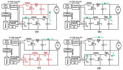
Figure 4 shows the four case studies of the projected controller based on the applied load to the EM. Figure 4 (a) corresponding to the case one operation of the main circuit, in that the upper part belongs to the battery current flow area and is in disable state represented with thin line.
Figure 4. Representation of four cases with MESS, converters, and EM, (a) case-I (b) case-II (c) case-III (d) case-IV
This indicates, no current flow zone from the battery to load even though the battery is fully charged. So, the entire current of EM need is, obtain from the UC which represents the IUC. Figure 4(b) illustrates the case two circuit model, in which the entire circuit area is an in-active state, due to which the total current of EM is supplied by both the two sources together. This can be represented by the combination of IBTC and IUC, which shows that the total current flows from two sources. Figure 4(c) shows the case three corresponding main circuit, in this, the UC side portion is in disable state and the remaining circuit is in an active state, which is represented with thick and thin lines. From this circuit, it is evident that the current flows from the battery to load only, which means IBTC only flows to the load. Finally, Figure 4 (d) representing the case four operation, in this case, the entire circuit is in an active state. As per the current direction shown in Figure 4(d) the IBTC flows to load and also to the UC side. This indicating that the battery current is feeding the load and supporting source UC due to the free-running period of the EM. Here IBTC and IUC representing the battery and UC currents corresponding to the two energy sources working under four cases.
The main purpose of the projected technique is to obtain an accurate transition between the energy sources of the MESS. This can be realized by the combination of a conventional controller and the control algorithm called CBC. The first important factor in this technique is considering speed as the main parameter, which plays a vital role during the switching of energy sources. The CBC is modeled based on the various speed changes corresponding to the load applied to the EM. After that, the CBC is combined with four different existed controllers made four hybrid controllers named CBC with ANN/FLC/PID/PI. Each hybrid controller provides unique results based on the applied load case to the EM. In this technique, no other parameters of the circuit are considered, and the entire senior has done with the speed parameter consideration.
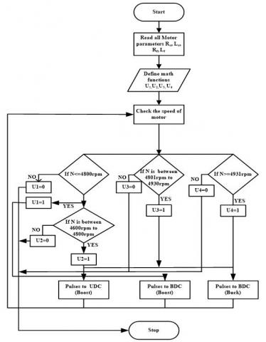
Figure 5 illustrating the step by step method of generation pulses to the induvial converters that may be for UDC and BDC. Initially, the speed parameter (NSPD) is considered, based on the NSPD the output signals of CBC generated. Those signals choose the operation of the two converter weather in boost or buck depending upon the load applied to the EM. The four different cases of operation of the main circuit corresponding to the projected control algorithm combine with conventional controllers demonstrated as:
(1) In case one operation, after applying the load to the EM motor, the speed of the EM held as NSPD≤4800 rpm, this starts the operation of the BDC as boost and pumps the current from UC to load. Due to this, the CBC produces output signals as one for only U1. This indicates that the total current required by the EM sent by the UC. So that is the reason why no current flows stated from the battery and no pulse produced to UDC. So, in this case of operation, the crest current is supplied by the supporting source.
(2) During case two operation, the CBC develops the output signals as one for both U1, U2 due to the NSPD range of the EM as 4600 rpm≤ NSPD≤ 4800 rpm. This happens corresponding to the applied load and initiates the operation of DC-DC converters under boost mode. Due to which the load current supplied by both sources together. This shows that the current flow direction from two sources to the load. So, in this case, the total current will flow from battery plus UC to the load, which means the UC giving support to the battery.
(3) In case three operation, the NSPD range is 4801rpm ≤ NSPD ≤ 4930 rpm, due to which the CBC develops outputs as one for only U3. This phenomenon starts the operation of BDC as a boost. So, the current will flow from the battery to load. This means, no current flow required from the UC, which indicates that the main source does not require any support from UC.
(4) When the NSPD range is NSPD$\geq$4931rpm then, this category comes under case four operation. In this case, the CBC can develop the output signal as one for U4, due to no load on the EM. This leads to flow current from the battery to load plus UC (charging). Due to this, the UC end converter works under buck mode and the battery end converter works as a boost.
Figure 5. Flow chart representation, how the controlled signals are producing to the converters
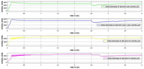
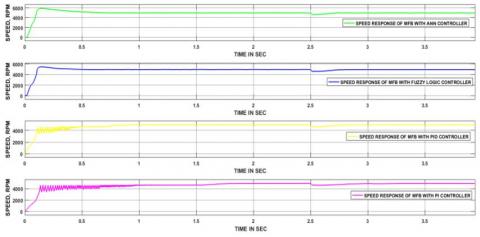
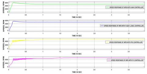
Figure 6. Case-I corresponding speed outcomes of the four hybrid controllers
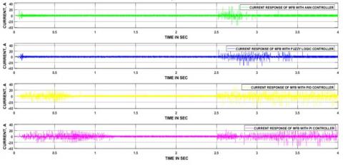
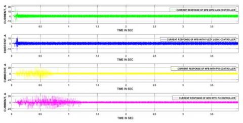
Figure 7. Four hybrid controllers output currents related to case-I
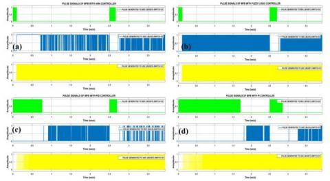
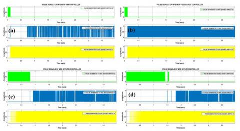
Figure 8. Stabilized pulses formed by (a) CBC+ANN, (b) CBC+FLC, (c) CBC+PID, (d) CBC+PI, related to case-I
7.1 Case-I Results
The speed range of the EM corresponding to case two is 4600 rpm≤ NSPD≤ 4800 rpm. Figure 6 detailing the speed curves related to four hybrid controllers, in which the first one (consider from top to bottom order) is the CBC+ANN and took 0.09 sec to obtain normal state. The second CBC+FLC took 0.1 sec, CBC+PID, PI took 0.85&1.45 sec, respectively. Thereafter all controllers’ responses settled at normal speed up to 2.5 sec. After that, 0.5 Nm load torque is applied to the EM, this causes the drop in the speed curve of all the controllers. The CBC+ ANN, FLC took 0.7 &1.1 sec time obtained their original state. On the other hand, remain two controllers’ responses unable to attain the previous state due to applied load.
The ripple in the current waveforms of the EM related to four controllers is shown in Figure 7. The curve represented in order from CBC+ANN, FLC, PID, and PI, which are from top to bottom. The first response (CNC+ANN), obesely took less time to reach the normal state at starting, on the other hand, last response (CBC+PI) took more time to attain a normal state. Thereafter, every controller response displaying the normal current of the EM up to 2.5 sec. At 2.5 sec, all controllers’ responses drawn huge current, and settled after some thins happens in case of CBC+ANN & FLC and remain two controllers’ responses do not retain their original state, which is clear from Figure 7.
Figure 8 represents the normalized pulses of the converter’s switches corresponding to the four hybrid controllers. In this work, the operation of the converter plays a vital role during the switching of energy sources. This means, without the proper operation of converters the transition of the source will not be fruitful as per the vehicle dynamics. In four controllers’ cases, each having three switching signals related to the type of operation of the converter. One of the main advantages of this work is at a time three switches are not in operation. Depending upon the case study, the ON/OFF states of the switches will change, which will reduce the losses during switching. At starting, UC can start the EM, after some time the battery also comes into the picture, thereafter battery exclusively supplies to load and UC. This same phenomenon takes place in four hybrid controllers during starting and the converters UDC, BDC also reacts as per the speed of the EM. After that, case one related load is applied at 2.5 sec, corresponding to this switch S3 (BDC Switch), and becomes an active state and remain two (S1&S2) are in OFF mode. This indicating that the total current is flowing to the load through S3. This will continue before reaching the normal state response of the EM.
7.2 Case-II Results
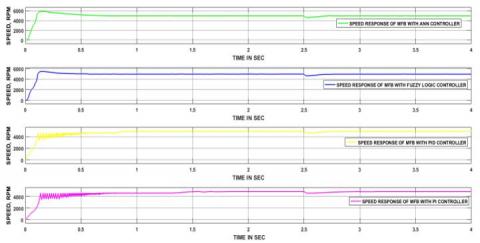
Figure 9 illustrating the four hybrid controllers output speed of the EM related to case two operation. Initially, four hybrid controllers took distinct times to reach the normal state, subsequently, no changes have been identified before load applied to the EM. Among all the controller the CBC+ANN took less time (0.09 sec), where remain CBC+FLC, PID and PI took 0.1, 0.85 & 1.45 sec in corresponding order. After that, 0.45 Nm load torque is applied to the EM at 2.5 sec, due to which the NSPD of the EM reduces than its rated value (4600 rpm≤ NSPD≤ 4800 rpm). Thereafter four hybrid controllers took separate time to obtain its previous state of operation. Among all the controllers CBC+ANN took less (0.2 sec) time, on the other hand, CBC+ANN, PID, and PI took 0.25, 0.3, and 0.4 sec in order.
The spikes in the current waveforms of the four hybrid controllers are presented during starting as well as the load applied situations on the EM, which are clear form Figure 10. During starting of the EM took more than the rated current of the EM, this phenomenon happens in the case of four hybrid controllers’ outputs. And, after reaching normal state all controllers output current becomes stable and which is equal to 5 Amps, this will maintain before apply load to the EM.
After the apply load, each controller response took more than 20 Amps (average) current and this continued still normal position attained by the EM. Again, the output current of the individual controller main the normal value, which is equal to 5 Amps.
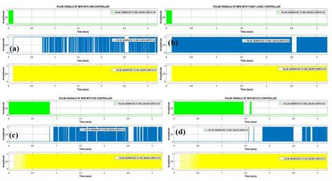
The case two related load is applied at 2.5 sec, corresponding to this, switch S3 (BDC Switch), S1(UDC switch) become active state and S2 is in OFF mode. This indicating that the total current is flowing to the load through S1 & S3. Figure 11 (a) illustrates the CBC+ANN normalized pulses, in that the pulses are produced to S1 & S2 as per the speed of the EM, in the same way, Figure (b), (c) & (d) representing the remain controllers CBC+FLC, PID & PI controllers stabilized signals. Here, in four controllers’ case, the stabilized signals are given to only two switches (S1 & S3). All those ON/OFF conditions of the three switches corresponding to four controllers’ responses are represented clearly in Figure 11. Finally, from the operation state of the converter, it is presumed that two switches (S1 & S3) are in ON state at a time, to meet the EM requirement.
Figure 9. Case-II corresponding speed outcomes of the four hybrid controllers
Figure 10. Four hybrid controllers output currents related to case-II
Figure 11. Stabilized pulses formed by (a) CBC+ANN, (b) CBC+FLC, (c) CBC+PID, (d) CBC+PI, related to case-II
7.3 Case-III Results
Figure 12 shows the speed curves of the EM related to four hybrid controllers. Here hybrid controller’s response is displayed from CBC+ANN to CBC+PI, in between that CBC+FLC & CBC+PID will present. In the case of CBC+ANN, FLC no considerable spikes are observed, whereas in CBC+PID, PI controller case lot of disturbances are present, and all this happens during the starting of the EM. After that, every controller response took a unique time to obtain a normal operation state. At 2.5 sec case three corresponding load is applied, due to which the NSPD range maintained as 4801rpm ≤ NSPD ≤ 4930 rpm. After that, the CBC+ANN, FLC, PID & PI took 0.11, 0.12, 0.15 & 0.3 sec to attain their previous state.
Figure 13 shows all hybrid controllers corresponding output current of the EM. In this, four hybrid controllers’ responses took unique periods to obtain normal state during starting as well after applied condition. Among all the controller, the CBC+ANN took minimum time, whereas CBC+PI hybrid controller took max time to reach normal position related to both starting and load applied situations. And in case three operation the current drawn by EM related to each controller response is equal or less than the rated value.
The case three-related load is applied at 2.5 sec, due to which switch S1(UDC switch) becomes an active state, and S2 & S3 are in OFF mode. This indicating that the total current is flowing to the load through S1. Figure 14 (a) illustrates the CBC+ANN normalized pulses, in that the pulses are produced to S1 as per the speed of the EM, in the same way, Figure (b), (c) & (d) representing the remain controllers CBC+FLC, PID & PI controllers stabilized signals. Here, in four controllers’ case, the stabilized signals are given to only one switch (S1). All those ON/OFF conditions of the three switches corresponding to four controllers’ responses are represented clearly in Figure 14. Finally, from the operation state of the converter, it is presumed that one switch (S1) is in ON state at a time, to meet the EM requirement.
7.4 Case-IV Results
Figure 15 illustrates the EM speed curves of the EM related to four hybrid controller responses. In case four operations, the EM is running with the load-free condition. Due to that, no speed disturbances are presented in four hybrid controller responses after reaching normal, during starting.
Four hybrid controllers’ responses related to the EM output current is respected in Figure 16. During case four, EM is rotating with load free, this causes the no current ripple present in the all controllers responses, once after reaching normal state.
No load is applied at 2.5 sec related to case four, due to this, switch S2 (BDC Switch), S1(UDC switch) become an active state and S3 is in OFF mode. This indicating that the total current is flowing to the load, UC through S1 & S2. Figure 17 (a) illustrates the CBC+ANN normalized pulses, in that the pulses are produced to S1 & S2 as per the speed of the EM, in the same way, Figure (b), (c) & (d) representing the remain controllers CBC+FLC, PID & PI controllers stabilized signals. Here, in four controllers’ case, the stabilized signals are given to only two switches (S1 & S2). All those ON/OFF conditions of the three switches corresponding to four controllers’ responses are represented clearly in Figure 17. Finally, from the operation state of the converter, it is presumed that two switches (S1 & S2) are in ON state at a time, to meet the EM requirement.
Figure 12. Case-III corresponding speed outcomes of the four hybrid controllers
Figure 13. Four hybrid controllers output currents related to case-II
Figure 14. Stabilized pulses formed by (a) CBC+ANN, (b) CBC+FLC, (c) CBC+PID, (d) CBC+PI, related to case-III
Figure 15. Case-IV corresponding speed outcomes of the four hybrid controllers
Figure 16. Four hybrid controllers output currents related to case-IV
Figure 17. Stabilized pulses formed by (a) CBC+ANN, (b) CBC+FLC, (c) CBC+PID, (d) CBC+PI, related to case-IV
Table 1 illustrating the comparative analysis of four controllers with unique load conditions. In case-I operation, the CBC+ANN & FLC controllers took 0.7 & 1.1 sec in order, and the other two controllers (CBC+PID & PI) unable to obtain a normal state. During case-II operation, the CBC plus ANN/FLC/PID/PI controllers took 0.2/0.25/0.3 0.4 sec time to attain the original state. In case-III operation, the CBC plus ANN/FLC/PID/PI controllers have taken 0.1/0.12/0.15/0.3 sec time to reach a stable state. In case-IV, no load is applied to the EM due to which no times measured corresponding to load applied.
Table 2 demonstrates the comparison among four hybrid controllers corresponding to the time domain specifications. From these analogies, the CBC+ANN providing better results than the other three controllers.
Table 3 shows the, four controller comparison related to starting and rated load applied case, how all controllers are reacting for that how much time is taken by each controller. This is obtained to know the performance of the controllers, particularly in those two situations. From table 3, it is evident that the CBC+ANN exhibiting better results among all the controllers.
Table 1. Summarized representation of four different modes corresponding to the speed of the EM
|
Controller |
Time is taken to attain the original position of the response (sec) |
|||
|
CBC+ANN |
CBC+FLC |
CBC+PID |
CBC+PI |
|
|
Case-I |
0.7 |
1.1 |
Unable to attain the original state |
Unable to attain the original state |
|
Case-II |
0.2 |
0.25 |
0.3 |
0.4 |
|
Case-III |
0.1 |
0.12 |
0.15 |
0.3 |
|
Case-IV |
No-load condition |
|||
Table 2. Time-domain factors based comparative analysis related to four hybrid controllers
|
Parameter Controller |
Delay time (sec) |
Rise time (sec) |
Peak time (sec) |
Settling time (sec) |
Maximum peak overshoot (%) |
|
CBC+PI |
0.15 |
1.4 |
1.5 |
1.45 |
4 |
|
CBC+PID |
0.1 |
0.7 |
0.8 |
0.85 |
4 |
|
CBC+FLC |
0.09 |
0.1 |
0.15 |
0.1 |
10 |
|
CBC+ANN |
0.07 |
0.09 |
0.15 |
0.09 |
12 |
Table 3. Comparison between starting and transient time is taken by three different controllers
|
Controller |
Rated load time (sec) |
Starting time(sec) |
|
CBC+ANN |
0.1 |
0.09 |
|
CBC+FLC |
0.12 |
0.1 |
|
CBC+PID |
0.15 |
0.85 |
|
CBC+PI |
0.3 |
1.45 |
In this work, a control method is considered to switch the battery and UC related to the speed of the EM. The CBC is designed by combining four distinct math functions which are separately realized as per the speed of the EM. To accomplish the key objective of the work, the designed CBC is combined with a conventional PI controller made a hybrid controller. This complete structure is applied to the main circuit in four different cases corresponding to the load applied to the EM. In case one, UC able to send total current to the load as per the vehicle requirement by operating BDC as a boost. During case two, the EM required current is supplied from two energy sources thorough BDC and UDC, operates in boost mode. Similarly, in case three, the total current of the load has drawn from the battery through UDC, which works a boost. Finally, in case four, the load and UC have drawn current from the battery through UDC (boost) and BDC (buck). The PI controller made the switching signals required by the converter; on the other hand, the CBC can control those pulse signals corresponding to the speed of the EM. Finally, with the recommended control strategy a soft transition is acquired between battery and UC as per EV requirement. Again, three other hybrid controllers are designed named CBC with PID, fuzzy logic, and ANN to perform the same task as CBC with PI controller. The four hybrid controllers took unique periods to reach the normal state and are accomplished with different time domain specifications corresponding to each controller response. After analyzing the four controller’s performance, it is evident the CBC+ANN has given better performance for this preferred application.
Appendix A1. pv Panel Specifications
|
Particular |
Description |
|
Power max (Pm) |
400 +/- 5% |
|
Short circuit current |
12.20 A |
|
Max power current |
11.40 A |
|
Maximum voltage |
35.20 V |
|
Open circuit voltage |
44.40 V |
|
Maximum system voltage |
1000 VDC |
|
No of cells in series |
72 |
|
No of the panel in parallel |
2 |
|
Max temperature |
250C |
|
Max irradiance |
1000 W/m2 |
Appendix A2. Parameters of the UC
|
Nominal capacitance |
Series resistance |
Nominal voltage |
Series capacitors |
Parallel capacitors |
Operating temperature |
|
500 F |
2.1e-3 ohms |
6 V |
6 |
1 |
250C |
Appendix A3. Parameters of the battery
|
Rated Voltage |
Rated capacity |
Initial SOC |
Response time of the battery (s) |
Fully charged voltage |
|
6 V |
4.5 Ah |
99 % |
10 sec |
7.1 V |
Appendix A4. Parameters of the EM
|
Rated Voltage, Power, Speed |
Resistance (Rs) of the Stator phase (ohm) |
inductance (Ls) of the Stator phase (H) |
Flat area Back EMF (degrees) |
Inertia, viscous damping, pole pairs, static [J(kg.m^2) F (Nms.) p ()] |
|
12 V 0.268 HP 5000 RPM |
1.16/2 |
194e-6/2 |
120 |
[3.4e-6 1e-7 1] |
[1] Akar, F., Yakup, T., Bulent, V. (2016). An energy management strategy for a concept battery/ultracapacitor electric vehicle with improved battery life. IEEE Transactions on Transportation Electrification, 3(1): 191-200. https://doi.org/10.1109/TTE.2016.2638640
[2] Wang, B.F., Zhang, X., Manandhar, U., Gooi, H.B., Liu, Y., Tan, X. (2019). Bidirectional Three-Level Cascaded Converter with Deadbeat Control for HESS in Solar-Assisted Electric Vehicles. IEEE Transactions on Transportation Electrification, 5(4): 1190-201. https://doi.org/10.1109/TTE.2019.2939927
[3] Chaudhari, K., Ukil, A., Kumar, K.N., Manandhar, U., Kollimalla, S.K. (2017). Hybrid optimization for economic deployment of ESS in PV-integrated EV charging stations. IEEE Transactions on Industrial Informatics, 14(1): 106-16. https://doi.org/10.1109/TII.2017.2713481
[4] Hussin, M.A., Abdalla, A.N., Ishak, R., Abdullah, R., Ali, Z.M. (2011). Study on improving electric vehicle drive range using solar energy. IEEE, International Conference on Electrical, Control and Computer Engineering 2011 (InECCE), Pahang, Malaysia, 373-376. https://doi.org/10.1109/INECCE.2011.5953909
[5] Korkas, C.D., Baldi, S., Yuan, S., Kosmatopoulos, E.B. (2017). An adaptive learning-based approach for nearly optimal dynamic charging of electric vehicle fleets. IEEE Transactions on Intelligent Transportation Systems, 19(7): 2066-75. https://doi.org/10.1109/TITS.2017.2737477
[6] Mohamed, A., Salehi, V., Ma, T., Mohammed, O. (2013). Real-time energy management algorithm for plug-in hybrid electric vehicle charging parks involving sustainable energy. IEEE Transactions on Sustainable Energy, 5(2): 577-86. https://doi.org/10.1109/TSTE.2013.2278544
[7] Li, J., Zhang, M., Yang, Q., Zhang, Z., Yuan, W. (2016). SMES/battery hybrid energy storage system for electric buses. IEEE Transactions on Applied Superconductivity, 26(4): 1-5. https://doi.org/10.1109/TASC.2016.2527730
[8] Shen, J., Khaligh, A. (2016). Design and real-time controller implementation for a battery-ultracapacitor hybrid energy storage system. IEEE Transactions on Industrial Informatics, 12(5): 1910-1918. https://doi.org/10.1109/TII.2016.2575798
[9] Trovao, J.P., Roux, M.A., Ménard, É., Dubois, M.R (2017). Energy-and power-split management of dual energy storage system for a three-wheel electric vehicle. IEEE Trans. Veh. Technol, 66(7): 5540-5550. https://doi.org/10.1109/TVT.2016.2636282
[10] Chaudhari, K., Ukil, A., Kumar, K.N., Manandhar, U., Kollimalla, S.K. (2018). Hybrid optimization for the economic deployment of ESS in PV-integrated EV charging stations. IEEE Transactions on Industrial Informatics, 14(1): 106-116. https://doi.org/10.1109/TII.2017.2713481
[11] Mesbahi, T., Rizoug, N., Bartholomeüs, P., Sadoun, R., Khenfri, F., Le Moigne, P. (2017). Optimal Energy Management for a Li-Ion Battery/Supercapacitor Hybrid Energy Storage System Based on a Particle Swarm Optimization Incorporating Nelder–Mead Simplex Approach. IEEE Transactions on Intelligent Vehicles, 2(2): 99-110. https://doi.org/10.1109/TIV.2017.2720464
[12] Lu, X., Chen, Y., Fu, M., Wang, H. (2019). Multi-Objective Optimization-Based Real-Time Control Strategy for Battery/Ultracapacitor Hybrid Energy Management Systems. IEEE Access, 115(7): 11640-11650. https://doi.org/10.1109/ACCESS.2019.2891884