Jianwei Deng | Li Cao*
OPEN ACCESS
As an important tool for studying the biological and sport dynamic principles of human motion, biomechanical sensors are widely used in the related studies. In order to clarify the role of biosensors in human motion, this paper designed Polyvinylidene Fluoride (PVDF) piezoelectric sensors and applied them to in situ high leg lift movement to analyze muscle biomechanics. The results showed that PVDF sensors had a good effect on the study of the biomechanics of human motion and could provide technical support for the study of human motion.
PVDF biomechanical sensor, motion test
With the continuous development of science and technology, the study of biomechanics in human movement is deepening. Sports biomechanics is a discipline which combines biology with kinematics to study the laws of human movement [1]. Human movement is completed through the control of the relevant parts of the body, with features of complexity, diversity and flexibility. Earlier researches on human movement were generally realized through the observation and analysis of moving videos or moving images. By extracting and tracking the contours of the body during movement and analyzing the obtained data, the human action is determined [2]. However, the early research on human motion through video images only stays on the twodimensional level and can not comprehensively analyze the characteristics of human motion from the three-dimensional perspective. With the development of materials science and biology, it has been found that electrical signals would be generated during muscle contraction and relaxation during human movement. The method of collecting human motion information based on electromyogram (EMG) signals was proposed. But in the early stage, electrodes were inserted into muscles to collect EMG signals. This method did too much harm to human body and caused movement distortion and large errors in the collected signal data. Although the acquisition of surface EMG signals appeared later avoids electrode insertion and improves safety, EMG signals are relatively weak and vulnerable to external factors. The emergence of piezoelectric materials provides a new method for collecting motion information of human muscles. This paper collected motion information of human muscles using Polyvinylidene Fluoride (PVDF) piezoelectric material. When piezoelectric material was deformed under pressure, electric charge would generate. The larger the deformation, the larger the charge. The deformation of human muscles during movement will produce pressure on objects close to the surface. Therefore, PVDF was served as a sensor to collect the motion information of human muscles. Comparing with the EMG signal method, the method adopted in this paper was safer, more stable and more accurate as the electrode as the electrode was unnecessary to be inserted, piezoelectric material which is lowly sensitive to external factors was used to produce current and electric charge only needed to be ampli-tude by amplifying circuit. PVDF plays a great role in the study of biomechanics, and many researchers have made relevant studies. Yang et al. [3] applied the PVDF material to sensors and demonstrated its good effect in the application of human motion sensing. Fuh et al. [4] also used PVDF material as the raw material for sensors and put the made sensors into gloves, socks and bandages to carry out detection on different human movements, with good results achieved. Bifulco et al. [5] used the PVDF piezoelectric thin film sensor to detect the heartbeat and respiration rate during movement. PVDF film has good flexibility and human resistance characteristics as well as light weight and large frequency span and is the main sensor material [6] in biomedical sci-ence. In this paper, PVDF material is applied to sensor production and the produced sensor is applied to the detection of human motion so as to determine the role of PVDF piezoelectric sensors in the detection of human biomechanics. Accordingly, we develop the design parameters of this new sensor in the following section.
2.1 Arm beam design
The elasticity of the elastic beam was designed as 100 times that of PVDF film.
$\kappa_{l}=\vartheta_{l} / E_{l}$ (1)
$\vartheta_{P V D F}=\kappa_{P V D F} \times E_{P D D F}=\vartheta_{l} \times E_{P V D F} / E_{l}$ (2)
The charge generated by the PVDF piezoelectric film is:
$Q=\gamma S=\mu_{31} \times \vartheta_{P V D F} \times S=\mu_{31} \times \vartheta_{1} \times S \times E_{P V D F} / E_{l}$ (3)
$U=Q / C_{a}=\mu_{31} \times \vartheta_{l} \times S \times E_{P V D F} /\left(E_{l} \times C_{a}\right)$ (4)
when the post-pole circuit is expanded by 20 times, the following can be obtained:
$U_{i}=20 U=\mu_{31} \times \vartheta_{l} \times S \times E_{P V D F} /\left(E_{l} \times C_{a}\right)$ (5)
where κ is a dielectric constant, ϑ refers to the stress, E1 refers to the elastic value of the cantilever beam, EPVDF refers to the PVDF elasticity, Q refers to the total film charge, U refers to the voltage value of Q, Ca refers to the equivalent capacitance of PVDF, γ refers to the charge per unit area, μ refers to the piezoelectric constant, S refers to the film area and Ui refers to the output voltage.
The positive strain of the equal strain cantilever beam in length is:
$\kappa_{x}=6 F L /\left(E_{l} t_{i} g^{2}\right)$ (6)
$\vartheta_{x}=6 F L /\left(t_{i} g^{2}\right)$ (7)
where $F$ refers to the vertical force of the endpoint, $L$ refers to the length of the cantilever beam, g refers to the thickness of the cantilever beam, $t_{i}$ refers to the root width and $x$ refers to the strain. The film strain is $k x^{\prime}=\kappa x$ and the membrane stress is $\vartheta x^{\prime}=E_{P V D F} k x^{\prime}$ '. The voltage produced by the PVDF film is:
$Q=\gamma S=\mu_{31} \vartheta x^{\prime} S$ (8)
$U=Q / C_{a}=\mu_{31} \vartheta x^{\prime} S / C_{a}$ (9)
The voltage was amplified by 20 times after the circuit posterior pole was adjusted, then:
$U_{i}=20 U=20 \mu_{31} \vartheta x^{\prime} S / C_{a}$ (10)
$W=U_{i} / F=20 \mu_{31} \vartheta x^{\prime} S /\left(C_{a} \times F\right)$ (11)
where W refers to the sensitivity, the higher the value of W, the larger the sensitivity. The larger the voltage produced by PVDF film, the greater the pressure.
2.2 Conditioning circuit design
According to equation (3) and (4), the weak charge of PVDF film after compression can not be measured directly. Instead, it needs to be amplified and transferred to voltage signals for collection. Charge amplifier is an important device to amplify the charge and a two-stage amplifier composing operational amplifiers. The first stage op amp is a high output impedance gain with capacitive feedback. When the sensor surface static insulation resistance is 1 TΩ and the dynamic force is 100Hz, CA3130 high input impedance operational amplifier is needed for help. The feedback resistor of the amplifier is 10 MΩ and it can enlarge by 2000. The second level is voltage amplification, and the standard is the amplification of the operation circuit, with the interval easy to collect to be -5 ~ +5 V.
2.3 Power circuit design
Power is a very important part of the process of signal processing. Unstable DC voltage will directly affect the normal work, resulting in noise [7]. In order to meet the working voltage and power requirements, the power supply circuit is designed. Here, 5V external DC voltage is selected. After voltage stabilization, the chip and operational amplifier are provided with power supply services.
2.4 Sensor array
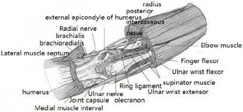
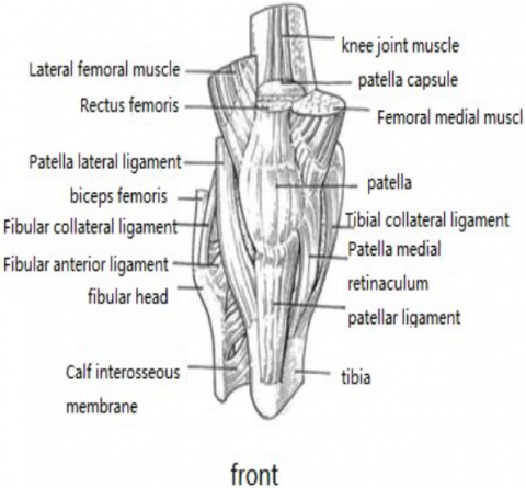
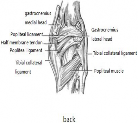
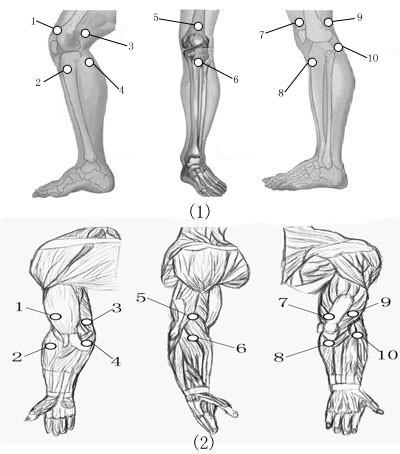
As shown in Figure 1, the elbow joint is mainly composed of the humerus, the humeral joint, the radial shoulder proximal joint and the brachiopodal joint. Being the most vulnerable joint, the knee joint is mainly composed of biceps femoris, gastrocnemius and half-membrane tendon, as shown in Figure 2. In order to better collect the muscle group information of the elbow joint and the knee joint during movement, PVDF sensors are placed on the corresponding muscle group locations. Due to the great range of motion in actual movement, the PVDF sensors need to be fixed well. In this study, thin copper sheets are used. Before the placement, the linkage position needs to be polished with abrasive paper to increase the sense of smoothness. Then, it is washed with acetone. Afterwards, conductive silver is applied to paste the PVDF film on the sensor, with plastic wrap for reinforcement protection. Then, 40 sensors are attached to the elbow and knee joint, as shown in Figure 3.
Figure 1. The elbow joint
Figure 2. The knee joint
Figure 3. Locations of sensors
The performance of the sensor is tested before the experiment. When the amplitude and frequency of the excitation signal are changed, which can be reflected by sensor response, and the waveform results are ideal, it indicates that the PVDF sensor can effectively collect infor-mation. The biomechanical test of human motion is carried out on the ground, which requires the experimenters with their knee joints and elbow joints pasted with sensors to do in situ high leg lift movement. In the course of the movement, the experimenters’ bodies are kept upright and their center of gravity maintained in the middle position, with the arm swinging and leg lifting actions coordinated. It is considered as the completion criteria when the included angle between the thigh and the leg and the one between the thigh and the knee are right angles while the other leg is being lift up. In addition, the supporting leg should stand straight, with the tiptoes touching the ground and the heel leaving the ground. The high leg lift time is 20min.
4.1 Sensor performance
Experiments show that when the pressure signal is 15N, the interference is strong; when the pressure signal is 150N, the collected signal quality increases, but the interference is still very significant; when the pressure signal is 250N, the sensor waveform is smoother, and the interference signal is not strong; when the pressure signal is located at 650N to 1250N, the linearity of the sensor is higher and the response is better. When the pressure signal exceeds 2050N, the signal waveform of the sensor begins to be distorted, the waveform is not smooth and the signal strength is weak. Hence, when the pressure signal is at 650N to 1250N, the sensor performance is the best. Also, the deviation of the response frequency of the sensor is correlated with the excitation frequency. When the excitation frequency is 800Hz, the sensor response deviation is the minimum.
4.2 Elbow joint
During the in situ high leg lift movement, the elbow plays a role to balance the body. And the angle between the upper arm and forearm is a right angle.
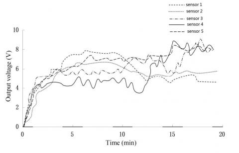
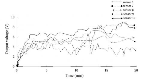
It can be seen from Figure 4 and 5 that the force condition of each muscle group in the elbow joint is different. In figure 4, the output voltage of each sensor tends to rise with the increase of time, indicating that the load of each muscle group is significantly increased. In figure 5, the output voltage of sensor 6 is smaller than that of the others and the muscle group of sensor 6 is the elbow joint brachioradialis muscle, indicating that the load during arm swinging is small.
Figure 4. The output voltage of sensor 1-5 on the elbow joint
Figure 5. The output voltage of sensor 6-10 on the elbow joint
4.3 Knee joint
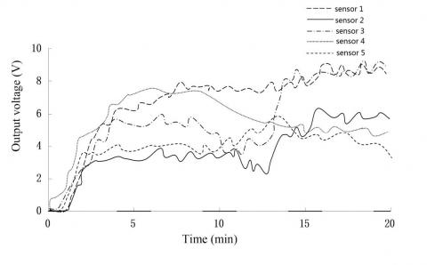
The knee joint plays a key role in the in situ high leg lift movement. The movement has higher requirements on legs than on arms, so the load on legs is larger than on arms, as shown in Figure 6.
Figure 6. The output voltage of sensor 1-5 on the knee joint
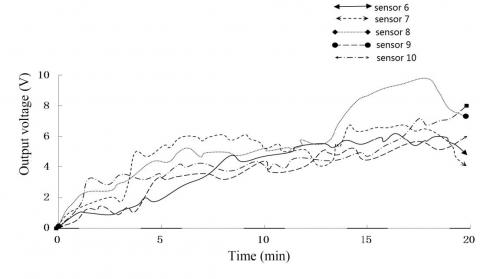
Figure 7. The output voltage of sensor 6-10 on the knee joint
As shown in Figure 6 and 7, as the output voltage of each muscle group on the knee joint is different, the load also varies. The voltage of sensor 1 has been showing a high output state, the corresponding mus-cle group is the medial femoral muscle, indicating the medial femoral muscle in the high leg movement suffered greater pressure. As for sen-sor 9, when the movement time reaches 15min, the output voltage of the sensor has been significantly improved, indicating that the load on the lateral muscle increases, so does the pressure.
With good sensing features, PVDF film can be used in sensors to increase their sensing feature. On this basis, this paper designed a PVDF sensor and applied it to the biomechanical study of human mo-tion. Through the piezoelectric information collection of each muscle group on the elbow joint and knee joint in the in situ high leg lift move-ment, the biomechanical characteristics of the elbow joint and the knee joint in controlling the muscle groups were analyzed. In the study of the elbow, since the elbow does not play a decisive role, the load on the muscles did not show a significant difference. While in the study of the knee, the load on parts of the muscles was large and the corresponding pressure was large.
Aritan [8] analyzed the biomechanics of human motion by establish-ing a nonlinear lens distortion model. Iskra et al. [9] analyzed the bio-mechanics of the centrifugal force and the ability water in the 400m hurdle. Through testing the performance of the sensor, it is found that the method proposed in this paper has the advantages of high accuracy and easy operation compared with other researchers. Through the study of the output waveforms of the elbow and knee joints, it is proved that the method can effectively obtain the human movement information. However, due to a lack of time and capacity, there remain shortcom-ings, which need to be overcome in future works.
The results obtained in this work shows that: 1) PVDF sensor had the best response performance when the pressure signal was between 250 and 1250 N, and the interference was obvious below or beyond this range; 2) in the measurement of elbow joint, it was noticed from the voltage output of the sensor that the stress condition of each muscle group of the elbow joint was different in the process of movement, and with the increase of time, the load of both arms was small in the pro-cess of elevating the leg in situ; 3) in the measurement of the knee joint, it was noticed from the voltage output of the sensor that the stress of each muscle group of the knee joint varied in the process of exercise and increased with time, in a high-output state for a long time, and the load of the leg was large in the process of elevating the leg in situ; 4) biomechanical sensor has a great role in the biomechanical detection of human motion, which is worthy of promotion and has good prospects for development.
[1] Laudner K, Wong R, Onuki T, et al., Journal of Science & Medi-cine in Sport, 18(5), 581 (2014).
[2] Paul S N, Singh Y J., International Journal of Signal Processing Image Processing & Pattern Recognition, 7, 99 (2014).
[3] Yang Y J, Aziz S, Mehdi S M, et al., Journal of Electronic Materi-als, 1, (2017).
[4] Fuh Y K, Ho H C., Nanotechnology, 27(9), 095401 (2016).
[5] Bifulco P, Gargiulo G, D'Angelo G, et al., IMEKO-International Measurement Federation Secretariat, 4, 786 (2014).
[6] Li Y, Lee D K, Jin Y K, et al., Energy & Environmental Science, 5(10), 8950 (2012).
[7] Berglund N, Gentz B., Siam Journal on Mathematical Analysis, 46(1), 310 (2012).
[8] Aritan S., Measurement, 43(6), 739 (2010).
[9] Iskra J, Coh M., Human Movement, 12(4), 315 (2011).