R. Yokeswaran* | V. Vijayan | T. Karthikeyan | B. Suresh Kumar | G. Sathish Kumar
OPEN ACCESS
The surface modification utilizing SiC (70μm) powder preplacement by TIG welding has been performed on the surface of duplex stainless steel(S32205). The different activities, for example, turning and filling are performed on the surface of duplex stainless steel with changing powder content. The surface layer is described with Rockwell C hardness tester and scanning electron microscope instrument (SEM). It was discovered that prepared of filing operation C65 from substrate hardness C20 delivered greatest hardness of the microstructure demonstrates that arrangement of dendrite phase because of liquifying of SiC. It increases the hardness of the material.
duplex stainless steel, rockwell C hardness tester, scanning electron microscope, microstructure.
1.1 Surface modification
Surface modification is altering the surface of a material by transporting physical, chemical or biological characteristics not the same as the ones initially found on the surface of a material. The change is typically made to strong materials. In the previous work they modified surface of DSS with SiC by varying parameters such as current, voltage and heat input. In this study we have taken nine samples where three were normal, three were modified turned in lathe and three were filed manually with using rough file. Then SiC powder content was varied such as 0.5mg/mm2, 1mg/mm2 and 1.5 mg/mm2. After coating, parameters such as current and gas pressure are varied in the TIG torch melting technique. All the samples are tested in Rockwell hardness tester, best samples are analyzed in SEM and optical microscopy. Finally results are com-pared with previous work of duplex stainless steel.
Surface engineering of a microalloyed steel to enhance the re-sistance to wear, the impact of three diverse protecting gases on the microstructure and hardness of tracks liquified along the sur-face utilizing a TIG torch was investigated. [1]. Heat input regard-ed is the parameter straight forwardly affecting the hardening speed. Tungsten carbide modification in the specimen(S2), which was upgraded with high powder empower rate, low process speed and high Heat input data and which made a think solidification the base mass setback was recorded [2]. They considered the micro-structure and hot erosion lead of Ni/Al-Cr composite claddings created by TIG on a 310 SS substrate. This change was credited to the course of action of a cautious oxide layer of Al2O3 NiAl-10%Cr have more assurance than NiAl-5%cr [3]. To build up the hardness and wear opposition of the alloyed surface, in the alloyed layers because of hard stages, disintegration of SiC and the near-ness of graphite which decrease the coefficient of grinding [4]., They broke down the impacts of preplaced powder sythesis on the cross sectional microstructures and surface hardness of the created coatings[5].
To progress and increment the wear, erosion assurance of steel and holds the properties at higher temperature. In this examination, beat tungsten idle gas (TIG) cladding process was finished to store stellite 6 on plain carbon steel plate [6], wear opposition of SAE 4140 steel surfaces can be upgraded by independently liquifying what's ore, alloying the sur- confront with a preplaced high carbon ferro-chromium powder layer, utilizing a TIG circular segment warm source. It was seen that the warm input for circular segment liquefying what's more, the thickness of preplaced high carbon ferrochr omium powder layer for surface alloying signicantly in-fluence the hardness what's more, wear obstruction of the surfaces. As the warm input was diminished the microstructure changed from bainite to martensite [7], Upgrade mechanical quality, impen-etrable to heat and erosion. Residual stress increases well ordered from the weld center and accomplishes the most outrageous at warm influenced zone (HAZ) and abatements far away [8]. They examine the microstructure and micro hardness of layer and shape imperfection free surface layer. Fusion zone achieves Mg2Si and FeSi IMCs microstructure. Alloyed layer hardness as high as 330HV0.3 [9]. To examine the copper composite cladding on steel substrate with the impact of cladding current and hardness of Cu/Fe in cladding [10]. To build enthusiasm for collaboration of surface in relative movement gathering for growing elite compo-site coatings, expanded component content in the microstructure and hardness, mass misfortunes are likewise diminished [11] To expand the weariness strength of modern segment and avert corro-sion cracking and wear. The surface hardness was expanded when contrasted from peened with unpeened sample.[12], To investigate the microstructure of composite claddings layer. The smaller scale hardness of composite cladding layer. The miniaturized scale hard-ness of steel/press interface was lower than the copper/steel inter-face [13]., To enhance the hardness, the mean hardness of AISI 1045 medium carbon was expanded with high volume of fraction. Their passageway and redissolution into the weld pool along these lines enhance Ti recuperation from the pre-put layer [14].
Studied the TIG-cold metal transfer hybrid welding process is proposed. Compared with conventional TIG metal inert gas. In addition to TIG can improve the wet ability of molten metal. They identify the TIG-CMT hybrid process is suitable for the multi pass-es welding of aluminium alloy [15]. Considered the material of AISI 4340. In this material they enhance the property of hardness. The hardness will be enhanced by utilizing TIG welding in shifting arcing current and curve travel speed. The microstructures are ex-amined under the optical microscope [16]. hardness and wear re-sistance of SAE 4140 steel surfaces can be enhanced by separately melting and alloying the sur- face with a preplaced high carbon ferrochromium powder layer, using a TIG arc heat source [17]. Considered the material of AA6082 in this enhances the mechani-cal properties. They enhance the mechanical properties by expan-sion of Ti and Sr on the moved wire of AA4043 utilizing TIG weld. In it they demonstrate that the blend expansion of Ti and Sr can be compelling composite modifier [18]. [19], examined the material of AISI 8620. Surface adjustment of steel got by the Tungsten Inert Gas Arcing. TIGA handling is powerful to create high surface hardness with harder internal core. The metallurgical characteristics of adjusted zones are administered by the proportionate change of martensite, bainite and pro-eutectoid ferrite., Studied the material of Tic-Ni-CaF2 to reduce the wear rate and co-efficient of friction by composite coating. CaF2 content, dilution coating in steel ma-trix altered the micro hardness and corresponding wear property. The coating revealed by SEM and EDS analysis [20]. Contemplat-ed the welding technique on duplex stainless steel and ferrite steel by utilizing advanced dynamic TIG welding. Here welding was done at various oxygen substance in the shielding gas. The adjust-ment in the fracture pass alongside the difference in the microstruc-ture [21].
NiTi was kept on AISI 316 stainless steel by TIG surfacing pro-cess going for increasing cavitation corrosion protection. Micro-hardness was in excess of 500Hv cavitation corrosion rate was increased [22 TIG surface alloying of SiC/C powders with AISI 4140 steel is a promising approach that can be used to produce hard and wear-resistant layers.. [23]. Studied the material of Al-mg-Zr-Er alloy. In this study addition of er in which they weld the metal using TIG welding. Here analyzed the microstructure of base metal and welded zone by optical microscopy, electron probe micro ana-lyzer and transmission electron microscopy. They find out that strength was mainly improved by er exists in primary phase and Al3Er in secondary phase on the weld fusion zone [24] To expand the wear and corrosion rate of steel and change the microstructure and mechanical properties of steel. FeCr, FeMo and FeTi powders were effectively alloyed on the surface of AISI 1020 steel utilizing TIG strategy. High hardness, non-appearance of crack and micro-structure change can be acquired [25].In this work we studied about the surface modification of duplex stainless steel by utilising the SiC by different activities like turning , filing , normal surface were studied.
The material used in this study was duplex stainless steel with grade of ASTM 2205. The specimen preparation was conducted by cutting the plate to the size of 50mm x 50mm x 4mm. Figure 1 shows the experimental procedure. Nine samples were taken into account. On this three were normal plate, another three were turned with lathe and another was filed manually. Preceding surface change, the sand paper is utilized to ground the surface of the sub-strate degreased in acetone. A powder of SiC with a molecule size of 70 μm was utilized as a covering material for surface alteration. Three kinds of SiC powder blend weighed of 0.5 mg/mm2, 1mg/mm2 and 1.5 mg/mm2was blended with two drops of polyvi-nyl acetic acid derivation (PVA) fastener and unsettled to shape glue with the guide of refined water and one drop of liquor. The binder was prepared in the magnetic stirrer as shown in figure 2. It was stirred nearly 12 hours to form a gel. SiC powder is grinded in the mortar and pestle apparatus. The gel of binder is poured into mortar and mixed with weighed quantity of SiC powder and it forms paste. Then the paste was pre-placed on the substrate surface and dried in furnace at 100 ºC for an hour to eliminate moisture. The coating of the steel substrate with pre-placement reinforcement of SiC was carried out using TIG torch melting technique.
Figure 1. Magnetic stirrer
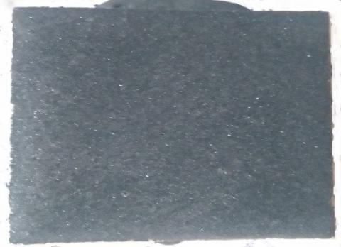
Figure 2. Coated sample
During TIG arc welding, argon shielding gas was channelled through the torch to protect the molten pool from excessive oxida-tion. After welding, the specimen preparation was cut into 10mm x 10mm and polished by standard mechanical polishing procedures and then etched with Kalling’s reagent to reveal the microstructure. The specimen was etched for 10 second and after that washed thor-oughly with running water promptly. Then the specimen was dried utilizing hot dryer for one minute. After that, the microstructure of the TIG re-solidified layer was analyzed using scanning electron microscope (SEM) and optical microscopy (OM). The profile of hardness variations for the cross section from surface towards sub-strate material was conducted using Rockwell hardness tester at a load of 150kgf with diamond indenter and 10 seconds. The operat-ing TIG torch cladding variables are shown in Table 1. The experi-mental design was done with the help of design of experiments [26-30].
Table 1. Cladding variables
|
No. of experiment |
SURFACE ROUGHNESS (μm) |
Current (A) |
GAS PRESSURE (N/m2) |
Powder content (mg/m2) |
|
1 |
3.02 |
60 |
20 |
0.5 |
|
2 |
3.02 |
80 |
40 |
1 |
|
3 |
3.02 |
100 |
60 |
1.5 |
|
4 |
1.15 |
60 |
40 |
0.5 |
|
5 |
1.15 |
80 |
20 |
1 |
|
6 |
1.15 |
100 |
40 |
1.5 |
|
7 |
0.763 |
60 |
60 |
0.5 |
|
8 |
0.763 |
80 |
60 |
1 |
|
9 |
0.763 |
100 |
20 |
1.5 |
4.1 Optical microscopy
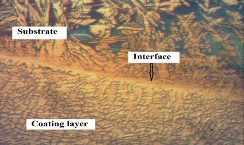
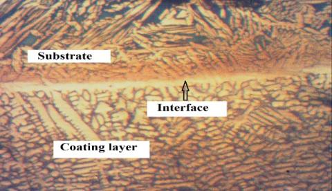
The modified surface under different welding variables was visu-ally inspected using optical microscopy and shown in figure 3. It is shown in the figure 4 phases formation as two phases separated with thin line. One phase is parent material structure and another phase is modified structure. The figure 5 shows the modified struc-ture. The figure 6 shows the actual structure of duplex stainless steel.
Figure 3. Surface topography of melt zone microstructure of DSS
Figure 4. Surface topography melt zone microstructure of DSS at higher magnification
Figure 5. Surface topography of modified DSS surface using SiC powder
Figure 6. Surface topography of actual structure of DSS
4.2 Microstructure of TIG melted modified duplex stainless steel
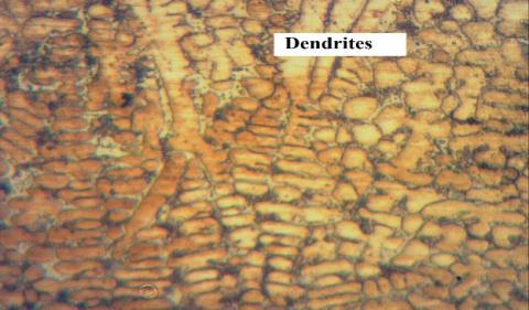
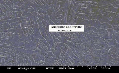
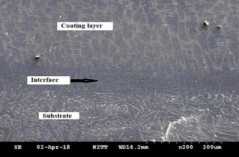
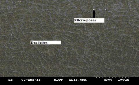
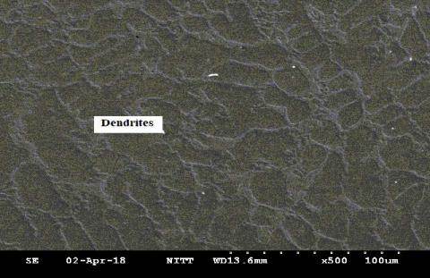
The re-solidified layer was captured to observe the microstruc-ture after TIG melting technique. The figure 7 shows the micro-structure of austenite and ferrite in duplex stainless steel. The filed plate was viewed in scanning electron microscope (SEM). It has high influential among the other experiment samples. Figure 8 shows the re-solidified and actual microstructure. Figure 9 shows the resolidified structure, when melted with 100A and kg/cm2, it revealed the thicker populated dendrite precipitation as seen in figure 9 and figure 10.
Figure 7. Microstructure of the duplex stainless steel
Figure 8. Microstructure of the SiC coating on duplex stainless steel
Figure 9. Microstructure of weld metal
Figure 10. Microstructure of weld metal in higher magnification
4.3 Hardness profile of TIG melted modified duplex stainless steel
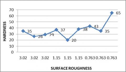
The specimens are tested in Rockwell hardness tester. The nine samples have the following hardness value are shown in table 2. From the figure 11 it is clearly understood that the hardness values increases with low surface roughness. This is mainly due to the dendrite structure formation in the weld metal fusion zone.
Table 2. Hardness value of samples
|
NO. OF EXPERIMENT |
SURFACE ROUGHNESS (μm) |
CURRENT (A) |
PRESSURE (×105 N/m2) |
HARDNESS VALUE |
|
1 |
3.02 |
60 |
20 |
C35 |
|
2 |
3.02 |
80 |
40 |
C26 |
|
3 |
3.02 |
100 |
60 |
C29 |
|
4 |
1.15 |
60 |
40 |
C37 |
|
5 |
1.15 |
80 |
20 |
C20 |
|
6 |
1.15 |
100 |
40 |
C38 |
|
7 |
0.763 |
60 |
60 |
C43 |
|
8 |
0.763 |
80 |
60 |
C35 |
|
9 |
0.763 |
100 |
20 |
C65 |
Figure 11. Surface Roughness vs hardness
Duplex stainless steel was surface coated with SiC powder the following results were obtained. Non appearance of any form of crack showed that a suitable degree of fusion was achieved be-tween duplex stainless steel and SiC, this is due to the effective bonding between the Sic and the base metal Based on the above results it can be concluded that modified surface by melting of SiC on duplex stainless steel using TIG melting has produced dendrite microstructure in the filled surface of roughness 0.763μm at 100A and 20kg/c 2 .The hardness showed the increment of 3 times higher than substrate material due to dendrite structure formation.
[1] P. Muñoz-Escalona, S. Mridha& T. N. Baker; Advances in Materials and Processing Tech, 1, 435 (2016).
[2] SonerBuytoz, Mustafa Ulutan, M. Mustafa Yildirim; Applied surface science, 252 ,1313 (2005)
[3] M. Atapour, S. Pourmohammadi, F. Ashrafizadeh; Canadian metallurgical quarterly, 1879 (2016).
[4] Mustafa ulutan, M. Mustafa Yildirim, SonerBuytoz; Osman N. celik; Tribology Transactions, 819, 76 (2010).
[5] K.A. Bello, M.A. Maleque, A.A. Adebisi and A. Dube, The Int. J. of surface engineering and coatings, 94, 211 (2016).
[6] F. Madadi, F. Asjrafozadej, M. shamanian; J. of alloys and compounds, 510, 71 (2012).
[7] M. Eroglu& S. Önalp; Materials Science andTechnology, 1544 (2006).
[8] Wenchun Jiang, Yun luo, Guodong Zhang, Wanchuck woo, S.T. Tu; Materials and design 630, 174 (2003).
[9] MahyaGhaffari, M. Heydarzadehsohi, A.A. Amadeh, Ali-rezavahedi Nemani; Advances in Materials and Processing Tech, 23, 2007.
[10] H.T. Wang, S.Q. Yang; Institute of materials and mining, 240, 420 (2008).
[11] M.H. Korkut, M.S. Gok; Industrial Lubrication and Tribology, 60, 189 (2008).
[12] A. SahayaGrinspan, R. Gnanamoorthy; Advanced Materials Research, 264 (2011).
[13] Long Wan, Yong-xian Huang, Shi-Xionglu, Ti-fang Huang S.K. Shaha; American J. of Applied Sci. 7, 815 (2010).
[14] Mahmoodsharifitabar, JalilVahdati khaki, and Mohsen Haddad Sabzevar; Int. J. of minerals, metallurgy and materials,30, 246 (2016).
[15] Ying Liang, Junq, Shen; J. of Materials Processing Tech 255, 161 (2018).
[16] Kumar, Sudhir, Ghosh, P.K., Kumar, Ravindra; J. of Materials Processing Tech, 249, 394 (2017).
[17] M. Eroglu& S. Önalp; Materials Science and Technology, 18, 1544 (2002).
[18] Bo Wang, Song-baiXuel Transactions of Nonferrous Metals Society of China, 136 (2017).
[19] Ravindra Kumar, P. K. Gosh; J. of Materials Processing Tech, 240, 420 (2017).
[20] P. Muñoz-Escalona, S. Mridha, T. N. Baker; Advances inMate-rials and Processing Technologies, 1, 435 (2015).
[21] Ying Zou, RintarwVei; Materials Science and Engineering 620,140 (2015).
[22] F.T. Cheng, K.H. Lo, H.C. Man, Surface and Coatings tech,172, 308 (2003).
[23] Mustafa Ulutan , M. Mustafa Yildirim , SonerBuytoz& Osman N. Çelik; Tribology Transactions, 54, 67, (2010)
[24] Yang Dongxia, Li Xiaoyan, NieZuoren, He Dingyong, Huang Hui, Zhang Guanzhen; Rare Metal Materials and Engineering, 41, 1713 (2012).
[25] V.V. Cay, S. Ozan, M.S. Gok; Int. J. of Advanced Mfg Tech, 63 (2010).
[26] A. Godwin Antony, S. Dinesh, K. Rajaguru, V. Vijayan; Me-chanics and Mechanical Engineering 21 (2), 193 (2017).
[27] S.Dinesh, A.Godwin Antony, K.Rajaguru and V.Vijayan; Me-chanics and Mechanical Engineering 21(1), 17 (2017).
[28] S.Dinesh, A.Godwin Antony, K.Rajaguru and V.Vijayan; Me-chanics and Mechanical Engineering 20 (4), 451 (2016).
[29] S.Dinesh, M. Prabhakaran, A.Godwin Antony, K.Rajaguru, V.Vijayan; Int. J. Pure and Applied Mathematics, 117, 385 (2017).
[30] S.Dinesh, A.Godwin Antony, K.Rajaguru, P.Parameswaran; Int. J. Mechanical and Production Engg Research and Develop-ment, 8(1), 65 (2018).