T. Sathish* | D. Chandramohan | V. Vijayan | P.J. Sebastian
OPEN ACCESS
In this present experimental studysix different metal matrix composites has been fabricated using pure copper (Cu) as a base material reinforced with silicon carbide (Sic) and graphite as one of the additives each time i.e., different volume fractions Sic and graph-ite. Powder state mixing technique was employed for the different constituent. After mixing, powders were poured in metallic die then spec-imens are sintered through Microwave sintering (2.45 GHz, 3.2 kW) and various tests such as hardness, compressive and microstructure of the composite specimens has been carried out.
Copper, silicon carbide, graphite, hardness test, compressive test, microstructure test
Metal matrix composites utilize the properties of the matrix (light weight, good thermal conductivity, ductility) and of the rein-forcement, usually ceramic (high stiffness, high wear resistance, low coefficient of thermal expansion)[1]. By this way it is possible to obtain a material characterized, if compared to the basic metal component, by high values of specific strength, stiffness, wear resistance, fatigue resistance and creep, corrosion resistance in certain aggressive environments[2]. However, cause to the pres-ence of the ceramic component, ductility, toughness and fracture to the coefficients of thermal expansion and thermal conductivity decrease.Many researchers attempted to sinter metal powder by microwave sintering [3] and they made a comparative evaluation on mechanical properties of sintered metal powders such as Fe–Ni, Fe–Cu and copper– TiC–graphite hybrid composites through mi-crowave and conventional methods. Microwave sintered speci-mens exhibited better mechanical properties. Microwave sintered Fe–Ni exhibited a modulus of rupture which is 60% higher than the conventionally sintered ones. It has been reported that copper steel alloys could be sintered using microwaves. These alloys ex-hibited better mechanical properties than conventionally sintered ones[4]. Experimental; study made on microwave sintering re-sponse of copper–graphite[5]. The problem of negative densifica-tion (expansion) through conventional sintering is surpassed by microwave sintering. Positive densification (shrinkage) was at-tributed to faster sintering which hinder the diffusion of tin parti-cles into copper lattice. Experimental investigation made on mag-nesium based composites for the improvement of mechanical properties of microwave sintered Al and Mg, to finer microstruc-ture[6]. Microwave radiation is useful in material processing activ-ities[7] it has been reported that microwaves are used for joining of ceramic and composites. Like lasers, microwaves are used for glazing of alumina–titania composite [8].Microwave sintering offers many advantages such as faster heating rate, lower sintering temperature, enhanced densification, smaller average grain size and an apparent reduction in activation energy in sintering. Some negative aspects of conventional sintering such as non-uniform heating, coarser microstructure and larger porosity can be mini-mized in microwave sintering[9]. The present study uses micro-wave hybrid heating for the development of metal matrix compo-sites. Microwave hybrid heating comprises simultaneous actions of microwave and microwave coupled radiative external heating, to realize the uniform and rapid heating[10]. Though some literature exists in microwave sintering of metal, no literature is available presently in the area of microwave sintering of copper based com-posites.
Table 1. Composition of specimens in %
|
Composite specimens |
Copper % |
SiC % |
Graphite % |
|
Specimen 1 |
90 |
5 |
5 |
|
Specimen 2 |
85 |
10 |
5 |
|
Specimen 3 |
80 |
15 |
5 |
|
Specimen 4 |
85 |
5 |
10 |
|
Specimen 5 |
80 |
10 |
10 |
|
Specimen 6 |
75 |
15 |
10 |
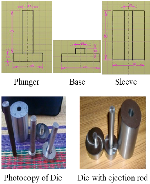
Table 2. Dimension and photography of Die with ejection rod
2.1 Materials
Copper-SiliconCarbide–graphite composites were manufactured through powder metallurgy (P/M) route. Electrolytic copper pow-der having average grain size of 47µm was mixed with the Silicon Carbide 37 µm size graphite powder of 50µm size.Copper powder was mixed with various volume fractions of Silicon carbide powder 5%, 10%, 15% And Graphite 5%,10% in manual pestle mortar for uniform mixing[11].Table.1 shows composition of specimens.
In order to obtain the proper mixing for duration of approximate-ly 1 hr is maintain for mixing the powders in the pestle mortar. Mixed powders were preheated at 150 oC in a muffle furnace to evaporate any volatile matter.
2.2 Composite fabrication
The D-2 Steel material was used for fabrication of die. D-2 Steel having high chromium content gives it corrosion resisting proper-ties in the hardened condition and it possess extremely high wear resisting properties. Dimension specification and fabricated die as shown in table 2. By using this die six differentComposition of specimens (shown in table 3) has been fabricated. The preheated powders were uniaxially compacted in a CTM machine at a load of 20ton to obtain cylinder shaped specimens having dimension of 15mmdiameter and 23 mm height with approximate pressure starts from 500Mpa to 1000Mpa for the plunger diameter of the die. Prior to sintering;the mixture was cold pressed into a cylindrical compact in a metal die of 15 mm in diameter under an axial pressure of 280 MPa[12].
2.3 Microwave sintering and characterizations
The green compacts were kept inside the hybrid microwave sin-tering setup. Preliminary sintering trials were conducted for the sintering temperature range of 850 ◦C and 900 ◦C and isothermal holding time range of 10–60 min. Sintering condition which emerged from the trial experiment has been extended to copper with various volume fractions of Sic and graphite composite. The microwave simultaneously interact with the green body sample, i.e. couple with green body sample and generates the heat internally due to penetrating feature of microwave in powder compacted sam-ples.. Two sets of green samples were sintered for each condition in order to assess the variation in processing and for the reproducibil-ity of final properties. In all the cases, the power of microwave was controlled to 20% of maximum available power and the heating rate was also set within 25o C /min for one set of samples for 60 mins. at 850 o C and another samples at 50 o C /min for 10 mins at 900 o C that is rapid fast. After the definite isothermal holding time, the samples were allowed to cool in the furnace[13].A 3.2 kW in-dustrial microwave furnace (2.45 GHz) was used in this study. Microwave sintering setup was designed to have two layers of ele-ments, i.e. one is transparent to microwave and the other is absorb-er of microwaves for uniform heating. The alumina wool (transparent to microwave) was used for preserving the heat inside the crucible SiC fencing was used as a susceptor (microwave ab-sorbing element). SiC fencing not only provides hybrid heating facility but also reduces the thermal gradient and this promotes crack free components[14-18]. Accurate temperature of samples was monitored using a ‘K’ type thermocouple. The microwave sintering setup used in the present investigation and Sintered speci-mens are shown in table 3.
Table 3. Fabrication and sintering of composite specimens
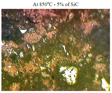
At 850oC - 5% of SiC Two fields have been captured for images of the microstructure. The photo micrographs shows the completely fusion areas during sintering with negligible quantum of Free copper left un-fused. The matrix also shows the presence of grey particles of Sic and dark agglomer-ated particles of free graphite in the copper matrix. The sintered matrix of copper shows very fine equi-axed grains of copper.
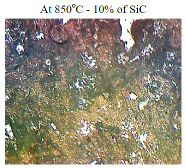
At 850oC - 10% of SiC Two fields have been captured for images of the microstructure. The photo micrographs shows the completely fusion areas during sintering with negligible quantum of Free copper left un-fused. The matrix also shows the presence of grey particles of Sic and dark agglomer-ated particles of free graphite in the copper matrix. The sintered matrix of copper shows very fine equi-axed grains of copper. As more percentage of SiC is mixed large and fine particles of SiC is distributed in the matrix.
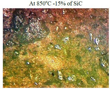
At 850oC -15% of SiC Two fields have been captured for images of the microstructure. The photo micrographs shows the completely fusion areas during sintering with negligible quantum of Free copper left un-fused. The matrix also shows the presence of grey particles of Sic and dark agglomer-ated particles of free graphite in the copper matrix. The sintered matrix of copper shows very fine equi-axed grains of copper. As more percentage of SiC is mixed large and fine particles of SiC is distributed in the matrix.
At 900oC-5%SiC Two fields have been captured for images of the micro-structure. The photo micrographs shows the completely fusion areas during sintering with negligible quantum of Free copper left un-fused. The matrix also shows the presence of grey particles of Sic and dark agglomerated particles of free graphite in the copper matrix. The sintered matrix of copper shows very fine equi-axed grains of copper. As more percentage of SiC is mixed large and fine particles of SiC is distributed in the matrix.
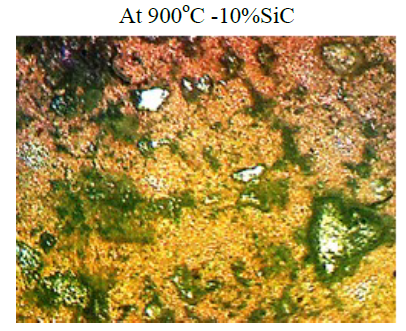
At 900oC -10%SiC Two fields have been captured for images of the micro-structure. The photo micrographs shows the completely fusion areas during sintering with negligible quantum of Free copper left un-fused. The matrix also shows the presence of grey particles of Sic and dark agglomerated particles of free graphite in the copper matrix. The sintered matrix of copper shows very fine equi-axed grains of copper.
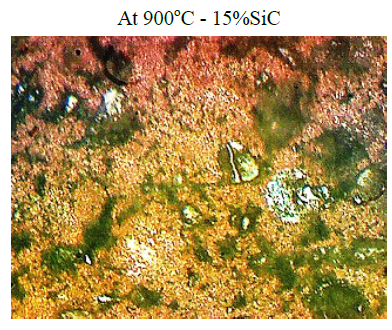
At 900oC - 15%SiC Two fields have been captured for images of the micro-structure. The photo micrographs shows the completely fusion areas during sintering with negligible quantum of Free copper left un-fused. The matrix also shows the presence of grey particles of Sic and dark agglomerated particles of free graphite in the copper matrix. The sintered matrix of copper shows very fine equi-axed grains of copper. Only large grains of copper are left unfused.
Table 4. Microstructure test result on composite specimens
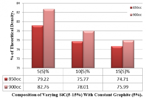
Figure 1. Density Result For Constant Graphite 5%
2.4 Physical property
Density test is done for finding the theoretical density and sin-tered density using the following formula to find out the percentage of the theoretical density of the every samples for different compo-sition.
Theoretical density = (ρ of Cu x Vd fraction of the Cu) + (ρ of SiC x Vd fraction of the SiC) + (ρ of Gr x Vd fraction of the Gr)
Sintered Density = (Weight of sample in air / loss of sample weight) x Density of Water. Or Density = mass /volume
Density of the composites was measured by using Archimedes principle, First the dry weight
Hardness test was carried out on Vickers’s micro hardness test-ing machine. Prior to the hardness test both side of the specimens were polished with emery paper to ensure for even distribution load. Testing load range: 10 grams to 1 Kg Load; Vernier caliper least count: 0.01 mm; Available Hardness testing Scale: HV, HRA, HRC, 15N, 30N etc., are specifications of the machine.
Compression test was carried out on Universal testing machine. Prior to the compression test both side of the specimens were pol-ished with emery paper to ensure for even distribution load. Lubri-cation was done by applying the grease on both sides of the sample so that the load could transfer without any Discontinuity and to minimize the friction at the interface. Loads of 400.800,1200 Kg etc with a constant interval 400 kg were applied until fracture ap-pear on the surface of the specimen. And finally change in dimen-sions along the length and diameter was noted at the load and the corresponding true stress verses true strain data was plotted to ob-tain flow curve in accordance with equation (1). Testing load range: Max 5 Ton; Digital Encoder: Auto Instruments; Gear rotation speed (for gradual loading): 1.25. 1.5 & 2.5 mm /min are specifica-tions of the machine.
$\sigma=\mathrm{k} \varepsilon \mathrm{n}$ (1)
Where, σ = True stress in MPa ; k= True strength; n= Strain Hard-ening exponent
Microstructure test
Internal micro structure of composite specimens was studied by optical microscope. Prior to this test Potassium Dichromate Solu-tion as Reagent (for copper) applied on both sides of the samples
for 10-30 sec[15].Table.4. shows microstructure test result on composite specimens.
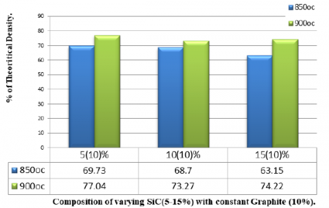
Figure 2. Density Result For Constant Graphite 10%
3.1 Density
Density Study Shows and decreasing trend with increase in con-tent of Silicon carbide.The percentage of theoretical density in-creased with increasing in sintering temperature soaking time for a particular composition may be due to better bonding as shown in Fig.1. and Fig.2.
3.2 Hardness test results
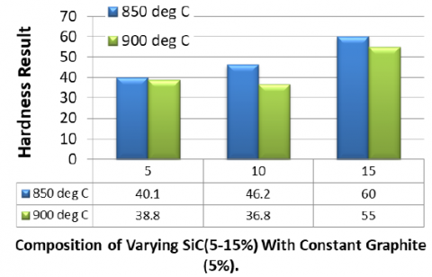
Hardness Study Shows an increasing trend with increase in con-tent of Silicon carbide. The temperature without soaking time shows the decreasing in Hardness value compare to low tempera-ture with soaking time This Effect is due to the better diffusion bonding between the materials during low temperature with soak-ing time during the microwave sintering. The Vickers’s Hardness Number (VHN) increases with the increase in SiC composition at 850oC sintering temperature. Few deviations occurred like slight decrease in hardness with increase in SiC percentage at the same sintering temperature mainly due to the presence of unwanted im-purities like oxygen, nitrogen, etc. The Vickers’s Hardness Number also increased with the increase in sintering temperature for a par-ticular composition of SiC with 5% of graphite with slight excep-tions at 900oC possibly due to impurities present or due to non-uniform heat distribution of SiC throughout the copper matrix Fig.3.
3.3 Compressive test results
Compressive strength of each composition is proved through the compressive strength machine it is also known as crush testing machine which is computerized one with the help of FEI software the breaking loads are calculated and compared and the displace-ment analysis also taken for the comparison numerical analysis.
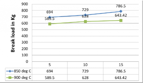
Maximum compressive strength is obtained at 15 vol. % SiC and const. 5 vol% of graphite reinforced MMC at 850oC with soaking time. It is observed that the compressive strength at 850 degrees with soaking time has produced more effective strength than the 900 degree with rapid fast that is without soaking time.
From the value It is observed that the compressive strength at 850 degrees with soaking time has produced more effective strength than the 900 degree with rapid fast that is without soaking time (Fig.4).
Figure 3. Hardness test Result
Figure 4. Compressive test result for Constant graphite 5%
The following conclusions can be drawn from the present inves-tigation
1. The copper-Silicon carbide-graphite composites were success-fully fabricated by microwave sintering process.
2. (a) The percentage theoretical density decreased with the in-crease in SiC and graphite content of the different samples sintered at a low temperature with soaking time where the percentage theo-retical density is decreased too short at a high temperature without soaking time.
(b) The percentage theoretical density increased with the soaking time with sintering temperature for a particular composition of the composite due to better bonding between the particles and reduc-tion in the number of voids at low temperature with soaking time.
3. (a) The Vickers’s Hardness Number (VHN) increases with the increase in SiC composition at 850oC sintering temperature. Few deviations occurred like slight decrease in hardness with increase in SiC percentage at the same sintering temperature mainly due to the presence of unwanted impurities like oxygen, nitrogen, etc.
(b) The Vicker's Hardness Number also increased with the in-crease in sintering temperature for a particular composition of SiC with 5% of graphite with slight exceptions at 900oC possibly due to impurities present or due to non-uniform heat distribution of SiC throughout the copper matrix.
4. The mixing of composite powder mixture results in very fine and homogeneously distribution of reinforcement throughout the matrix is studied through the microstructure test. It is observed that the sintering at 850 has produced more effective fused matrix com-pared to rapid sintering at 900 degrees.
5. Maximum compressive strength is obtained at 15 vol. % SiC and const. 5 vol% of graphite reinforced MMC at 850oC with soak-ing time. It is observed that the compressive strength at 850 degrees with soaking time has produced more effective strength than the 900 degree with rapid fast that is without soaking time.
6. Due to the presence of unwanted impurities like oxygen, etc are some of the reasons for the result variation caused in experi-mental analysis while compare displacement through the Ansys 14.0 Software. From that Displacement Analysis result concluded that the percentage error is decreased while the SiC content is in-creased with 850 degree temperature with soaking time.
[1] Sanders Jr., R.E; Kirk–Othmer Encyclopaedia of Chemical Technology, vol. 2, fifth ed., . 279 (2004)
[2] Rajkumar K and Aravindan S; Tribology International. 44, 347–358 (2011)
[3] Fathy A, Shehata F, Abdelhameed M and Elmahdy M; Materi-als and Design. 36: 100, (2012)
[4] Rajkumar, K., Aravindan, S; Journal of Materials Processing Technology 209: , 5601 (2009)
[5] M. Gupta, W.L.E. Wong; The Minerals, Metals & Materials Society, 423 (2014)
[6] Dewidar M M, and Lim J K; Journal of Composite Materials. 41(18): 2183 (2007)
[7] S. Chandrasekaran, TanmayBasak, S. Ramanathan; Journal of Materials Processing Technology. 211, 482 (2011)
[8] ChandrasekaranS,SrinivasanRamanathan; AICHE Journal. 58, 330 (2012)
[9] Ramesh C S , Noor Ahmed R , Mujeebu M A and Abdullah M Z; Materials and Design.30, 1957 (2009)
[10] Chandrakanth Reddy G, Rajkumar K, Aravindan S, Int J AdvManuf Technol. 48, 645 (2010)
[11] CelebiEfe G, Ipek M, Zeytin S, Bindal C; Composites Part B: Engineering. 43(4), 1813 (2012)
[12] Jennifer M. Ullbrand , Jose M. Cordoba , Javier Tamayo-Ariztondo , Maria R. Elizalde , Mats Nygren,Jon M. Molina-Aldareguia , Magnus Oden; Composites Science and Technolo-gy. 70, 2263 (2010)
[13] El-Kady O and Fathy A; Materials and Design. 54, 348 (2014)
[14] MohammadmehdiShabani, Mohammad HosseinPaydar, Reza Zamiri, Maryam Goodarzi, Mohammad Mohsen Moshksar; Journal of materials research and technology.5(1):5 (2016)
[15] Parameswaran P, Godwin Antony A,Dinesh S, Radhakrishnan K; Experimental study on mechanical and Corrosion character-istics of NAB alloy with the addition of chromium, Materials Today: Proceedings 5, 8089 (2018)
[16] A. Godwin Antony, S. Dinesh, K. Rajaguru, V. Vijayan; Me-chanics and Mechanical Engineering 21 (2), 193 (2017)
[17] S.Dinesh, A.Godwin Antony, K.Rajaguru and V.Vijayan; Me-chanics and Mechanical Engineering 21(1), 17 (2017)
[18] S.Dinesh, A.Godwin Antony, K.Rajaguru and V.Vijayan; Me-chanics and Mechanical Engineering 20 (4), 451 (2016)