Arkadiusz Smagala | Krzysztof Kecik*
© 2021 IIETA. This article is published by IIETA and is licensed under the CC BY 4.0 license (http://creativecommons.org/licenses/by/4.0/).
OPEN ACCESS
A numerical analysis of the nonlinear bearing model about two degrees of freedom has been presented in this paper. The contact between a ball and ring by Hertz theory is described. Influence of the number of balls, shaft rotation and clearance on the acceleration were investigated in detail. Three numbers of balls from 11 to 16 were analyzed. The clearance level in the range of 0-71μm has been studied. It has been shown that the acceleration responses are different, depending on the vibration direction and are usually higher when the radial internal clearance and the shaft speed are increased. The higher ball number caused that the accelerations decreased in both directions. Moreover, two dynamic indicators that can be used for comparison bearing dynamics have been proposed. These obtained results are useful for understanding the vibration response mechanism from a practical point of view.
bearing, modelling, vibration, dynamic indicators
Rolling element bearings are one of the important machine components used in industries like automotive, aerospace, railways, construction, mining, textile, etc. The term rolling bearings is defined as all types of bearings that use the rolling action of balls. At first glance, ball bearings are relatively simple mechanisms. However, analysis of their dynamics reveals that they are quite complex [1, 2]. Heavy loads and varying time and space dynamic loads caused that bearing dynamics is difficult to be unpredictable.
The bearings very often act as a source of vibration and noise. The finite number of rolling elements carrying loads in radially loaded bearings causes vibrations even if they are geometrically perfect [3]. Usually vibrations are generated by geometrical imperfections on the bearing components. These imperfections occurred during the manufacturing process and normal usage. Moreover, every rolling bearing is designed and manufactured with radial and axial clearance that is interpreted as the displacement of one ring relative to another. The initial internal clearance and after mounting usually becomes smaller [4]. Depending on the fitting conditions, the inner ring is expanding, the outer ring is contracting, and usually the internal clearance tends to decrease [5, 6]. As reported by Tiwari et al. [7-9], the internal clearance is also a source of vibration and introduced nonlinearity. The unwanted vibration and noise due to bearings operated at high-speed conditions are generated. The time-varying nonlinear contact forces, elastic deformations, which exist between different components of the rolling bearing are the main factors causing the nonlinear behaviour [10-13].
Ball bearings are the most popular bearing in engineering applications. Therefore, in the literature can be found a lot of papers concerning the analysis of bearing dynamics. Usually, the mathematical and numerical models are dedicated for improving and optimizing the bearing dynamics. In paper [14], the simplified practical approach for bearing analysis is used. The simplification is based on the analysis vibration in relation to two boundary positions of the inner ring support with even and odd number of rolling elements of a bearing. Moreover, it showed that the crucial influential parameters for vibration level are the internal radial clearance, the external radial load and the total number of rolling elements. Ahmadi et al. [15] proposed the nonlinear dynamic model including the finite size of the rolling element. The vibration response predicted by the proposed model was compared with the experimental results. Authors suggested that the proposed conception is more accurately predicted by classical literature models. Nataraj et al. [16] analytically investigated the dynamic behaviour of an unbalanced rotor-bearing system. Authors assumed that the unbalance effect due to cage run out is caused. The contact between the rolling elements and the race is assumed as a spring with nonlinear characteristics. Tiwari et al. [17] studied the effect of the radial internal clearance of the ball bearing in the model prepared based on the Timoshenko beam finite theory. Zhang et al. [18] investigated a comprehensive dynamic model of the rotor-bearing system with about five degrees of freedom. They investigated three types of excitations: the bearing waviness, the unbalanced force, and the finite number of balls. The stability problems of rotor-bearing systems are investigated in detail. Kogan et al. [19] proposed a new model for spall-rolling-element interaction. The nonlinear multibody model includes the interaction between the rolling element and a spalled outer race. Kong et al. [20] developed the vibration model of a ball bearing based on the Hertzian contact stress distribution. They compared the numerical and experimental signals in the time and frequency domains and showed a good correlation between them.
A dynamic model of the bearing is presented in the paper [21]. Authors demonstrated an interesting analysis of the offset distance and skew angle of the default and suggest that these parameters have a great influence on the bearing acceleration. Peterson et al. [22] used a new method for calculating and analyzing the quasi-static load distribution in ball bearings in gearbox and fan test. They analysed the problem of loss of load carrying capacity when balls pass through the defect. Moreover, they noted that the variation in bearing stiffness due to the defect introduces additional parametric excitation in the system.
Harsha et al. [4, 8] proposed an analytical model to predict nonlinear bearing-rotor system dynamic responses. They showed an analytical two degree of freedom model with clearance and nonlinear springs modelling the ball stiffness. The time histories, frequency spectra, and Poincare’ maps of the bearing dynamics are presented. Choi [23] showed the nonlinear behaviour of the rotor-bearing system. A Fourier and inverse Fourier transformation to determine the steady state have been applied.
Other problem in the bearing dynamics is modelling the damage. Patil et al. [24] demonstrated a theoretical model to predict the localized defect. The problem of defect size is also studied. The bearing element contact by the Hertz approach is described. Tandon and Choudhury [25] presented a review of different methods for localized and distributed fault detection. Singh et al. [26] analysed the vibration caused by the defect in the bearing. In this aim, they using the finite element method model that has been built in LS Dyna software. Choi and Meyer et al. [27] used the analytical method for detection the defects in the bearing dynamics. Chen and Kurfess [28] showed a model for defect size estimation. The defect size has been estimated from the experiment performed with 3-axis CNC. Liu and Guo [29] proposed an interesting method for bearing fault diagnosis. They used different methods of signal analysis like Ensemble Empirical Mode Decomposition (EEMD), Information Entropy (IE) and Random Forest (RF). The obtained results are promising for both cylindrical roller bearing and deep groove ball bearing.
Reviewer paper [30] showed a wide analysis of dynamic modelling and methods for fault detection. The authors give also the recommendations of future research works and problems to be solved.
In the paper, we expanded our conference paper [31]. The two degree of freedom bearing model with different configurations: ball numbers, clearance, and the rotatory shaft is studied. New dynamical indicators for bearing dynamics comparing are proposed. These indicators can be easy applied in practice to compare the bearing in various configurations. Additionally, this model can be used for the estimation of the acceleration level in the bearing. This allows to choose the optimal speeds, the clearance level and number of balls.
2.1 Assumptions
A typical rolling bearing consisted of outer and inner rings, ball elements, and the cage (Figure 1(a)). Usually between the rings and cage the positive internal clearance due the technological aspects are applied. The bearing during rotation causes vibration, which can be sometimes dangerous.
In the presented model, we assumed that the outer ring is mounted in non-deformable frame, and we neglected the mass of balls. The inner ring rotates with the spinning shaft. The deformation between the raceway and balls by the Hertz theory is described. The proposed model has a few assumptions like:
• the inner race is rotating with the spinning shaft,
• the outer race is fixed (no motion),
• no interaction between all rolling balls,
• the ball is modelled as the linear spring,
• the slipping effect of all balls is neglected,
• the deformations are described by the Hertz approach,
• the axial clearance and load have negligible influence.
2.2 Equations of motion
The physical model of the bearing is modelled as the mechanical system consists of linear dampers and springs. The ball is modelled as the spring, while the rings are assumed as the spring-damper structure. The contact between the ball and ring by the Hertz approach is described. Usually, the outer ring is mounted in the housing, while the inner ring on the shaft is fixed. The inner ring rotates together with a shaft, the balls make a rolling motion on the raceways. The crucial elements of the analysed system are balls and rings. Therefore, only these elements can be used to build the dynamic spring-damper model which in Figure 1(b) is shown.
Figure 1. Typical construction (a) and the 2DOF nonlinear model (b) of the rolling bearing
The equations of motion of the bearing inner race by the well-known Newton second law and the Hertz theory are described:
$m \ddot{x}+c \dot{x}+k x+k_{b} \sum_{j=1}^{z} H\left(\delta_{j}\right) \delta_{j}^{1,5} \cos \varphi_{j x}=0$ (1)
$m \ddot{y}+c \dot{y}+k y+k_{b} \sum_{j=1}^{z} H\left(\delta_{j}\right) \delta_{j}^{1.5} \sin \varphi_{j y}=F$ (2)
m is the mass of the shaft and inner ring, c, k are the linear damping and the stiffness of the shaft (with inner ring), respectively. F is the force (in the vertical direction) acting on the race of the bearing, caused by the weight of the shaft with the inner ring.
The nonlinear force between the ball and the raceway is described in paper [17]. Parameter kb parameter describes the stiffness of the ball, z means the number of balls, H(δ) is the Heaviside function that defines the deformability. If the rolling element is in contact with raceway then H(δ)=1, or lack of contact H(δ)=0. The deformation δ of each ball depends on the displacement of the shaft, the geometry parameters of the bearing and the clearance level. The total deformation of balls is the result of the relative displacement between the inner and outer rings (x, y), the angular position of the balls j, and the clearance Pd. The bearing deformation δj based on paper [16] is:
$\delta_{j}=\left(x_{s}\right) \cos \varphi_{j}+\left(y_{s}\right) \sin \varphi_{j}-P_{d}$ (3)
The angular position of the j-th ball jj is a result of the time t, the initial angular position of the cage f0 and cage’s angular speed wC. The jj and wc can be defined as follows:
$\varphi_{j}=\frac{2 \pi(j-1)}{z}+\omega_{c} t+\phi_{0}, \quad \omega_{c}=\left(1-\frac{D}{d_{m}}\right) \frac{\omega}{2}$ (4)
where, ω is the angular shaft speed, D is the diameter of the ball, and dm is the pitch diameter of the bearing.
2.3 Simulation parameters
The parameters of the bearing applied in the numerical simulation based on the commercial bearing denoted as 6009 in Table 1 are shown.
Table 1. Bearing simulation parameters
|
Parameters |
Values |
|
z |
11, 12, 13, 14, 15 |
|
D |
8.731 (mm) |
|
dm |
60 (mm) |
|
kb |
1.8978×10¹⁰(N/m) |
|
k |
4.241×10⁴ (N/m) |
|
c |
1376.8 (Ns/m) |
|
m |
0.48 (kg) |
The simulations were calculated for different numbers of balls, various clearance level and different rotary speeds. Different combinations of these parameters are studied. Note that the internal radial clearance in bearings can be easy modified in practice. The recommended ball numbers for this kind of bearing are from 11 to 15. More balls in a bearing cause better bearing’s performance and a higher static and dynamics load capacity which influence to lower vibrations. However, from a practical and economical point of view, each additional ball can increase a bearing’s weight and as its cost. This is economically important for serial production. Moreover, there are technological problems with the assembly of balls.
For the number of balls less than 11, the static and dynamic load capacity of the bearing would be so small that it would be appropriate to replace them with a bearing with smaller external dimensions.
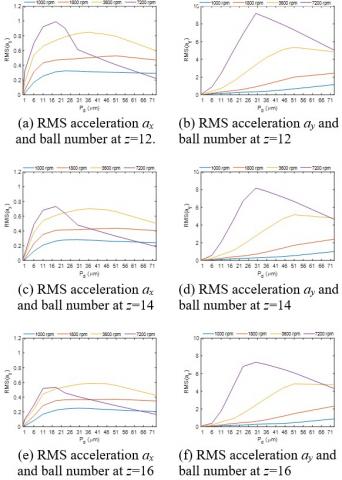
3.1 Ball number influence
Figure 2 shows the exemplary RMS accelerations in x (Figure 2(a), 2(c) and 2(d)) and y (Figure 2(b), 2(d) and 2(f)) directions versus the number of balls for the four different rotary speed n and different Pd. The numerical calculations were prepared for time simulation of 5s, but the first 2s were rejected as the transition time.
The blue line presents the result for n=1000 rpm, the red line for n=1800 rpm, the yellow line for n=3600 rpm, and the purple for n=7200 rpm. Analysis all diagrams, we can conclude that for all rotatory speeds, the RMS accelerations are smaller for more balls. This effect is simply to explain the more balls cause higher stiffness of the bearing.
Figure 2. Acceleration ax and ay vs. number of balls, obtained for x and y directions and different ball numbers
Note that the obtained relations between the number of balls and acceleration can be described by the linear function. Therefore, it can be simply implemented in numerical models.
In most cases for higher clearance level the acceleration is higher (Figures 2(a)-(f)). Interesting result is observed for the rotation speed n=7200 rpm and Pd=45mm (purple line in Fig. 2(e)). In this case, the acceleration is smaller than for n=3600 rpm and n=1800 rpm. This positive effect is probably due to the stabilization of the dynamics is caused. The similar unintuitive result is observed in the machining stability analysis (stability lobe diagram) [32], where an increase in rotational speed improves machinability. This result we will try verified by the experiment in future.
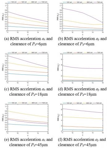
3.2 Clearance influence
Generally, the internal clearance is defined as the distance one bearing ring moves relative to the other. As shown in the literature review (and in the previous section), this parameter is essential.
Figures 3 (a)-(f) show the influence of the internal radial clearance on the root-mean-square acceleration in both directions. The investigations have been calculated for the bearing with balls: z=12 (Figures 3(a) and 3(b)), z=14 (Figures. 3(c) and 3(d)) and z=16 (Figure 3(e) and 3(f)).
Figure 3. Accelerations ax and ay vs. clearance obtained for x and y directions and for different clearance levels
RMS diagram analysis shows that for a rotation of n=1000 rpm the acceleration responses are nearly on the same level for the different number of balls (especially x direction, Figure 3(a)). In the y direction, a slight increase is observed (Figure 3(b)). The maximum acceleration (peak) in x direction for the clearance range of 11-45 μm is observed (Figure 3(a), (c) and (e)). While for y direction the maximal RMS(ay) is obtained for the range of 25-50 μm. The RMS of acceleration in the vertical direction is a few times higher than in the horizontal. This result is probably caused by the gravity force F. Comparing both directions, we can conclude that the vertical direction vibrations are much greater.
To sum up, as it can be seen, the acceleration result strongly responds in the function of the radial internal clearance and number of balls, especially at higher shaft speeds. As mentioned earlier, these parameters are crucial parameters from the practical point of view. Therefore, the contour maps (clearance- speed) in the next section are presented.
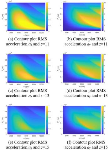
3.3 Two parameter analysis (Pd, n)
The next graphs (Figures 4 (a)-(f)) present 3D maps showing the acceleration areas for the combination of the radial clearance and the shaft’s rotation in the horizontal and vertical directions for three sets of number balls.
These plots clearly show that increase in the ball number causes that the RMS acceleration decreases (see Figure 4(e) and (f) in both directions. The large yellow large areas are significantly reduced. The most dangerous region in the horizontal direction occurs for a clearance of 0.00001-0.0007m and for the shaft rotation of 3000-800 rpm. While in the vertical direction the high acceleration region is located close to n » 5000-10000 rpm. Note that an increase in speed can reduce vibration.
Figure 4. Contour maps showing the influence of clearance and shaft rotation on the RMS accelerations for different ball numbers: z=11 (a) and (b), z=13 (c) and (d) and z=15 (e) and (f) in vertical and horizontal directions
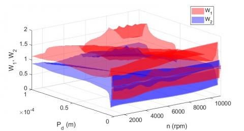
The rolling bearings have different diameters and different ball numbers. Therefore, their comparison is very difficult in practice. In order to quantitative comparison, four new dynamics bearing’s indicators (DBI) are proposed. These indicators characterize the ratio of root-mean-square acceleration amplitudes in the horizontal and vertical directions. In our analysis, we compare the bearing with balls 11 to 13 (W1 and W3), and 13 to 15 (W2 and W4). Note that the commercial bearing no. 6009 usually has 13 balls. Therefore, we assumed this value as primary. These indicators allow finding areas in which acceleration response values are lower.
The proposed DBI indicators have a simple formula:
$W_{1}=\frac{R M S x(11)}{R M S x(13)} \quad W_{2}=\frac{R M S x(15)}{R M S x(13)}$
$W_{3}=\frac{R M S y(11)}{R M S y(13)} \quad W_{4}=\frac{R M S y(15)}{R M S y(13)}$ (5)
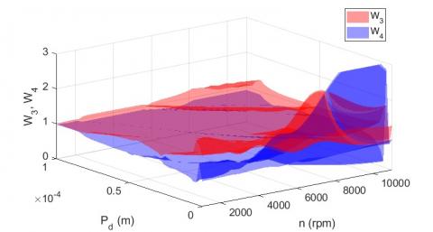
Indicator W1 defines the ratio of RMS values of acceleration in the horizontal direction bearing with 11 balls relative to 13. W2 is the ratio of RMS values of acceleration for the bearing with15 balls to 13. W3 is the ratio of RMS values of acceleration in the vertical direction for the bearing with 11 balls relative to 13. W4 is the ratio of RMS values of acceleration for the bearing with 15 balls to 13. The DBI values below 1 mean that the accelerations of the compared bearings are smaller relative to the bearing with 13 balls. In other words, the analysed bearing is better because the vibrations are lower.
Figure 5. 3D contour map of indicators W1 and W2 showing the comparison between balls consisting of 13 and 15 balls in x direction
Figure 6. 3D contour map of indicators W3 and W4 showing the comparison between balls consisting of 13 and 15 balls in y direction
Figures 5 and 6 present the indicators W1, W2, W3, and W4 for different values of radial internal clearance in the range from 0 to 0.0001 m for different values of rotary speed in the range from 1000 to 11000 rpm. For the horizontal direction, the RMS of acceleration value is lower for the bearing with 15 balls almost in the whole range of the rotary speed and clearance. For the vertical direction the acceleration value is lower for the bearing with 15 balls expecting the area where is the low clearance and high rotary speed.
The paper presents a numerical study of the two degree of freedom rolling bearing mode. The contact between the ring and ball is described by the Hertz theory. The detail analysis for different parameter configurations is done.
Analyzing all obtained results we can conclude, that the acceleration in the vertical direction is the most important due to the gravitational force. In this direction, the acceleration is several times greater. Moreover, the regions with high accelerations are more extensive (yellow color in contour maps). An increase in the number of balls leads to a lower vibration level. Change of the inertial radial clearance in a bearing is not so obvious. This depends also on the rotation of the shaft. For some range of the shaft rotation can be improved of the dynamics.
To compare the bearing dynamics we propose special dynamics indicators, which can be easy applied in practice. Analyzing all indicators we can find the region in which the accelerations are lower in both directions. Additionally, these indicators can be applied for the bearing parameters optimization.
The project/research was financed in the framework of the Young Research project at the Lublin University of Technology, contract no. FNM/30/2020.
|
m |
mass of inner race, kg |
|
c |
damping of the inner race, Ns/m |
|
k |
stiffness of the inner race, N/m |
|
kb |
contact stiffness, N/m |
|
z |
number of balls |
|
Pd |
Internal radial clearance, m |
|
D |
Ball diameter, m |
|
dm |
Pitch diameter,m |
|
$\delta$ |
deformation, m |
|
$\varphi$ |
position of ball, rad |
|
$\omega$ |
Angle shaft speed, rad/s |
|
$\omega_{c}$ |
angle cage speed, rad/s |
[1] Harris, T.A., Kotzalas, M.N. (2006). Essential Concepts of Bearing Technology (5th ed.). CRC Press.
[2] Cong, F., Chen, J., Dong, G., Pecht, M. (2013). Vibration model of rolling element bearings in a rotor-bearing system for fault diagnosis. Journal of Sound and Vibration, 332(8): 2081-2097. https://doi.org/10.1016/j.jsv.2012.11.029
[3] Tandon, N., Choudhury, A. (1999). A review of vibration and acoustic measurement methods for the detection of defects in rolling element bearings. Tribology International, 32(8): 469-480. https://doi.org/10.1016/S0301-679X(99)00077-8
[4] Harsha, S.P., Sandeep, K., Prakash, R. (2004). Non-linear dynamic behaviours of rolling element bearings due to surface waviness. Journal of Sound and Vibration, 272(3-5): 557-580. https://doi.org/10.1016/S0022-460X(03)00384-5
[5] Chudzik, A., Warda, B. (2019). Effect of radial internal clearance on the fatigue life of the radial cylindrical roller bearing. Eksploatacja i Niezawodnosc-Maintenance and Reliability, 21(2): 211-219. http://dx.doi.org/10.17531/ein.2019.2.4
[6] Changqing, B., Qingyu, X. (2006). Dynamic model of ball bearings with internal clearance and waviness. Journal of Sound and Vibration, 294(1-2): 23-48. https://doi.org/10.1016/j.jsv.2005.10.005
[7] Tiwari, M., Gupta, K., Prakash, O. (2000). Effect of radial internal clearance of a ball bearing on the dynamics of a balanced horizontal rotor. Journal of Sound and Vibration, 238(5): 723-756. https://doi.org/10.1006/jsvi.1999.3109
[8] Harsha, S.P., Sandeep, K., Prakash, R. (2003). The effect of speed of balanced rotor on nonlinear vibrations associated with ball bearings. International Journal of Mechanical Sciences, 45(4): 725-740. https://doi.org/10.1016/S0020-7403(03)00064-X
[9] Harris, T.A., Kotzalas, M.N. (2006). Rolling Bearing Analysis - 2 Volume Set (5th Edition). CRC Press.
[10] Singh, S., Kopke, U.G., Howard, C.Q., Petersen, D. (2014). Analyses of contact forces and vibration response for a defective rolling element bearing using an explicit dynamics finite element model. Journal of Sound and Vibration, 333(21): 5356-5377. http://dx.doi.org/10.1016%2Fj.jsv.2014.05.011
[11] Xu, L., Chatterton, S., Pennacchi, P. (2021). Rolling element bearing diagnosis based on singular value decomposition and composite squared envelope spectrum. Mechanical Systems and Signal Processing 148: 107174. https://doi.org/10.1016/j.ymssp.2020.107174
[12] Nivesrangsan, P., Jantarajirojkul, D. (2018). Bearing fault monitoring by comparison with main bearing frequency components using vibration signal. 5th International Conference on Business and Industrial Research, Bangkok, pp. 292-296. https://doi.org/10.1109/ICBIR.2018.8391209
[13] Nagale, V.V., Kirkire, M.S. (2014). A mathematical model to determine sensitivity of vibration signals for localized defects and to find effective number of balls in ball bearing. International Journal of Engineering Development and Research, 2(3): 3207-3214.
[14] Tomovic, R. (2020). A simplified mathematical model for the analysis of varying compliance vibrations of a rolling bearing. Applied Sciences, 10(2): 670. https://doi.org/10.3390/app10020670
[15] Ahmadi, A.M., Petersen, D., Howard, C. (2015). A nonlinear dynamic vibration model of defective bearings. The importance of modelling the finite size of rolling elements. Mechanical Systems and Signal Processing, 52-53: 309-326. https://doi.org/10.1016/j.ymssp.2014.06.006
[16] Nataraj, C., Harsha, S.P. (2008). The effect of bearing cage run-out on the nonlinear dynamics of a rotation shaft. Communications in Nonlinear Science and Numerical Simulation, 13(4): 822-838. https://doi.org/10.1016/j.cnsns.2006.07.010
[17] Tiwari, M., Gupta, K., Prakash, O. (2000). Effect of radial internal clearance of a ball bearing on the dynamics of a balanced horizontal rotor. Journal of Sound and Vibration, 238(5): 723-756. https://doi.org/10.1006/jsvi.1999.3109
[18] Zhang, X., Han, Q., Peng, Z., Chu, F. (2016). A comprehensive dynamic model to investigate the stability problems of the rotor-bearing system due to multiple excitations. Mechanical Systems and Signal Processing, 70-71: 1171-1192. https://doi.org/10.1016/j.ymssp.2015.10.006
[19] Kogan, G., Bortman, J., Klein. R. (2017). A new model for spall-rolling-element interaction. Nonlinear Dynamic, 87: 219-236. https://doi.org/10.1007/s11071-016-3037-1
[20] Kong, F., Huang, W., Jiang, Y., Wang, W., Zhao, X. (2018). A vibration model of ball bearings with a localized defect based on the Hertzian contact stress distribution. Shock and Vibration, Article ID 5424875. https://doi.org/10.1155/2018/5424875
[21] Liu, J., Xu, Y., Wang L., Xu, Z., Tang, C. (2019). Influence of the local defect distribution on vibration characteristics of ball bearings. Eksploatacja i Niezawodnosc - Maintenance and Reliability, 21(3): 485-492. http://dx.doi.org/10.17531/ein.2019.3.15
[22] Petersen, D., Howard, C., Sawalhi, N., Ahmadi, A.M., Singh, S. (2015). Analysis of bearing stiffness variations, contact forces and vibrations in radially loaded double row rolling element bearings with raceway defects. Mechanical Systems and Signal Processing, 50-51: 139-160. https://doi.org/10.1016/j.ymssp.2014.04.014
[23] Choi Y.S., Noah, S.T. (1987). Nonlinear steady state response of a rotor support system. Journal of Vibration and Acoustics, 109(3): 255-261. https://doi.org/10.1115/1.3269429
[24] Patil, M.S., Mathew, J., Rajendrakumar, P.K., Desai S. (2010). A theoretical model to predict the effect of localized defect on vibrations associated with ball bearing. International Journal of Mechanical Sciences, 52(9): 1193-1201. https://doi.org/10.1016/j.ijmecsci.2010.05.005
[25] Tandon, N., Choudhury, A. (1999). A review of vibration and acoustic measurement methods for the detection of defects in rolling element bearings. Tribology International, 32(8): 469-480. https://doi.org/10.1016/S0301-679X(99)00077-8
[26] Singh, S., Kopke, U.G., Howard, C.Q., Petersen, D. (2014). Analyses of contact forces and vibration response for a defective rolling element bearing using an explicit dynamics finite element model. Journal of Sound and Vibration, 333(21): 5356-5377. http://dx.doi.org/10.1016%2Fj.jsv.2014.05.011
[27] Meyer, L.D., Ahlgren, F.F., Weichbrodt, B. (1980). An analytic model for ball bearing vibrations to predict vibration response to distributed defects. Journal of Mechanical Design, 102(2): 205-210. https://doi.org/10.1115/1.3254731
[28] Chen, A., Kurfess, T.R. (2018). A new model for rolling element bearing defect size estimation. Measurement, 114: 144-149. https://doi.org/10.1016/j.measurement.2017.09.018
[29] Liu, Q., Guo, Y. (2015). Dynamic model of faulty rolling element bearing on double impact phenomenon. 2015 IEEE International Conference on Information and Automation, Lijiang, pp. 2017-2021. https://doi.org/10.1109/ICInfA.2015.7279620
[30] Liu, J., Shao, Y. (2018). Overview of dynamic modelling and analysis of rolling element bearings with localized and distributed faults. Nonlinear Dynamic, 93: 1765-1798. https://doi.org/10.1007/s11071-018-4314-y
[31] Smagala, A., Kecik, K. (2019). Nonlinear model and simulation of a rolling bearing. In IOP Conference Series: Materials Science and Engineering, 710(1): 012006. https://doi.org/10.1088/1757-899X/710/1/012006
[32] Kecik, K., Rusinek, R., Warminski, J. (2011). Stability lobes analysis of nickel superalloys milling. International Journal Bifurcation and Chaos, 21(10): 1-12. https://doi.org/10.1142/S0218127411030258