Narendra Kumar Muthukuri | Rajanand Patnaik Narasipuram* | Subbarao Mopidevi
© 2020 IIETA. This article is published by IIETA and is licensed under the CC BY 4.0 license (http://creativecommons.org/licenses/by/4.0/).
OPEN ACCESS
In recent years Multilevel Inverter (MLI) getting in popular due to its performance in field of medium and high-power applications. Many MLI’s like Diode-clamped, cascaded H-bridge, flying capacitor and hybrid cascaded H-bridge are introduced in 1970’s. But due to the draw backs like harmonic distortions researchers are concentrated on novel topologies. Recently nested configuration is gaining attention to researchers due to it is having an advantage of 3-phase design with a smaller number of components compared to traditional MLI topologies. Hence, this paper investigates the performance an advanced MLI named as Nested topology for 72V electric vehicle (EV) motor drive application for 1kW/1500 RPM system. It can generate near-sinusoidal voltages with only fundamental switching frequency, there is no electromagnetic interference (EMI) and also it gives easy operating EV and safer conditions. Furthermore, this paper inspects the analysis, benefits and control scheme for nested MLI for the use of EV motor drive applications. The simulations are carried out using Matlab/Simlink.
Electric Vehicle (EV), Plug-in Electric Vehicle (PEV), Total Harmonic Distortion (THD), Pulse Width Modulation (PWM), Multilevel Inverter (MLI)
Present days most of the vehicles are working by using oil’s, in future oil levels are completely down after (2050-2070). The global warming is unpredictably increasing unexpected level in present time and future also due to mostly use of oils in vehicles and some of the industries & the temperature level is also highly increasing in future [1]. Due to this reason all country in the world decided to use and develop the electric vehicles. The Indian government developed to start using electric vehicles on after 2020 increasing randomly. After 2025 the entire world usage of electric vehicles must be more than 5 million’s [2]. Abnormally development and controlling of electric vehicles possible by power electronic devices only. This electronic vehicle is not superiorly control, they can be completely eliminating the air pollution and majorly eliminate sound pollution [3]. The most of the future technology vehicles are hybrid electronic vehicles and high efficiency rechargeable battery vehicles. In olden days like nineteenth century oil levels are very high in the world, several industries and humans are used for transport purpose internal combustion engine (ICE), it has a more reliability but the internal combustion engine has done not much more efficiency. Table 1 gives the insightness of EV vs ICE. But now a day’s fuel levels decreasing unexpected level with day by day due to more usage of vehicles and also day by day atmosphere was polluted and this is also chance to earthquakes. That pollution mostly controlled by using electric vehicles only [4]. Mostly automobile systems are more and more effectively develop the electronic vehicles by using majorly different electricity for running the vehicles. From 2000 year some of the countries in the world set an esteemed target for usage of electrical vehicles by eliminating the oil usage and pollution. Norway is decided to reduce the oil usage and improve the use of electrical vehicle 29%, china 1.5%, nether land usage of electronic vehicles is 6.4% and sudden also use 3.4% electrical vehicles in preset days [5]. Those all countries are taking to initiative response to use electronic vehicles more than 30% after 2030. China, Britain and France were now decided to stop the usage of all fuel vehicles and completely ban the all oil-based vehicle production companies after 2040 [6].
Table 1. Difference between EV vs ICE
|
Electrical Vehicles (EV) |
Internal Combustion Engine (ICE) Vehicles |
|
|
|
|
|
|
|
|
|
|
|
|
|
|
|
|
|
|
|
|
|
|
|
|
|
|
|
|
|
|
|
to deliver maximum torque |
|
|
In early years, electrical vehicles are developed by using batteries in 1834, those batteries completely non-rechargeable type in the year of 1834. They are popularity will be increasing day by day in that time and after some years 1890 to 1920. After 1920 some of the industries developed the internal combustion type engines [7]. From all above reasons electrical vehicles are more and more precious technology to eliminate the pollution and earth quakes. Future electrical vehicles are highly able to work long distance with high power rating also with different un pollutant fuel sources. Most of the all countries in the world set a target usage of electrical vehicles are more than 40% after 2040 [8, 9].
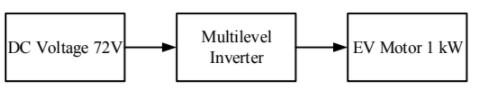
The multilevel inverters are intelligent to work more effectively on high power, high voltage and medium voltage, medium power and low power and low voltage applications [10]. Now a day this multilevel inverter is superiorly capable to work very effectively in electric vehicle (EV) after several years and also multilevel inverters are used to eliminate the harmonics with increasing levels and also it can develop stair case waveform which is nearer to sinusoidal waveform for n number of levels. The conceptual block diagram of EV power system is shown in Figure 1.
Figure 1. Conceptual block diagram of EV power system
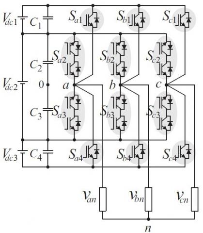
As shown in above Figure 2, it’s indicated the four-level nested multilevel inverter. In previously different types of inverters are there like flying, cascade, diode clamping, neutral clamping and etc. this inverter is latest inverter compare to all inverters, this inverter was operated by a nested mode, nested means above and below or center point legs are connecting the same point [11, 12]. Due to this reason nested inverter was superiorly work the four to infinity levels and also this inverter was used develop the highly predictable output levels as well as stair case outputs and also control the harmonics effectively. This inverter is one of the preferable methods compare to different type’s inverter families. Switching sequence of nested configuration four level inverter was shown in below [6].
The 4-level nested inverter gas mainly consist of two types of switches. One of the switches indicate the bidirectional control switches (Sx2 and Sx3) and the other switch indicates the controlled switches (Sx1 and Sx4) and here x is representing in terms of a, b, c (x = a, b, c). Table 2 gives the switching sequence, source will be same at all 3 points, by means Vdc1 and Vdc2 and Vdc3 will be same (Vdc1 = Vdc2 = Vdc3 = Vdc).
Table 2. Switching sequence of four level nested configuration inverter
|
Sx1 |
Sx2 |
Sx3 |
Sx4 |
vx0 |
|
1 |
0 |
0 |
0 |
Vdc1 + Vdc2/2 |
|
0 |
1 |
0 |
0 |
Vdc2/2 |
|
0 |
0 |
1 |
0 |
−Vdc2/2 |
|
0 |
0 |
0 |
1 |
−Vdc1 − Vdc2/2 |
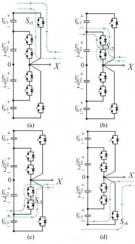
As shown in Figure 3 (a-d), it is indicating the positive currents and negative currents flows to the switches Sx1, Sx2, Sx3, Sx4. The controlled switches (Sx1-Sx4) are employed as inner leg switches and Sx2 and Sx3 are employed as outer leg switches. When the position of the switches is change in operating mode like as inner (Sx1-Sx4) or outer (Sx2-Sx3), then short circuit will appear on the outer leg switches [13-18].
Figure 2. Schematic diagram of four-level nested inverter
Figure 3 (a-d). Schematic figure of current flow direction for 4-level Nested MLI
2.1 Modulation technique
The nested configuration four level inverter was implemented by using sinusoidal level shift type carrier base pulse width modulation technique method. Schematic diagram of carrier dependent level shift PWM shown in bellow [19].
Figure 4. Schematic figure of level shift carrier dependent 4-level PWM inverter
As shown in Figure 4, that is completely based carrier dependent level shift PWM mode. In this method generally, carrier’s arrangements are three different types [20]. They are phase opposition disposition (POD) and alternative phase opposition disposition (APOD) and the last one is phase disposition (PD) [21]. In this paper we are majorly discuss only one technique, phase disposition mode (PD). In this PD method is applied to the four-level nested configuration, we are mainly taking 3 carriers in 4-level inverter, because number of carriers are must be equal to number of levels minus one [22, 23]. In PD dependent technique all carriers must be arrange the above direction on initial stage also like as carrier can be arranged as low value to high value on in this PD depended method or as well as zero to one and one to zero [24].
The 4-level Nested MLI Fed 3-Phase IM was simulated by using carrier dependent level shift PD PWM technique. Load voltage and current results are shown in below with total harmonics distortion as well. The parameters of 4-level nested configuration multilevel inverter with 3phase IM is shown in Table 3.
Table 3. Operating parameters for nested conjuration 4-level inverter with 3-phase IM
|
Parameters |
Values |
|
Nominal power |
1 kW |
|
Input Voltage |
72 V |
|
Frequency |
50 Hz |
|
Carrier frequency |
2 KHz |
|
Rotor nominal speed |
1480 rpm |
|
Stator resistance |
1.405 Ω |
|
Stator inductance |
0.5839 mH |
|
Rottor resistance |
1.395 Ω |
|
Rotor inductance |
0.5839 mH |
|
Mutual inductance |
172.2 mH |
|
Pole pairs |
2 |
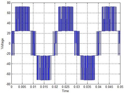
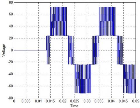
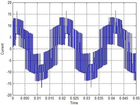
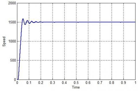
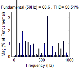
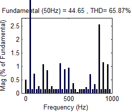
Figures 5-7 indicate the Load voltage waveform of Nested MLI fed 3-phase IM which is at a peak of 72 V for EV applications with a Load current of 13.86 A shown in Figure 8 Speed waveform of 1500 RPM for EV application is shown in Figure 9, Figure 10 & 11 represents the %THD of Nested MLI with 17.89% & 10.60% of voltage and current THD at Modulation Index 1.0. Figure 12 & 13 represents the %THD of Nested MLI with 50.15% and 30.43% at modulation index 0.8. Figure 14 & 15 represents the %THD of Nested MLI with 65.875% and 38.13% at modulation index 0.6.
Figure 5. Load voltage Van of Nested MLI Fed 3-Phase IM
Figure 6. Load voltage Vbn of Nested MLI Fed 3-Phase IM
Figure 7. Load voltage Vcn of Nested MLI Fed 3-Phase IM
Figure 8. Load current A of Nested MLI Fed 3-Phase IM
Figure 9. Speed waveform of nested MLI fed 3-phase IM
Figure 10. THD analysis of output load voltage at M=1.0
Figure 11. THD analysis of output load current at M=1.0
Figure 12. THD analysis of output load Voltage at M= 0.8
Figure 13. THD analysis of output load current at M= 0.8
Figure 14. THD analysis of output load voltage at M= 0.6
Figure 15. THD analysis of output load current at M= 0.6
The performance analysis of Nested MLI topology with respective to THD at different modulation indexes is given in Table 4.
Table 4. THD comparison at different modulation indexes
|
Modulation Index |
Load Voltage |
Load Current |
|
1.0 |
17.89 |
10.60 |
|
0.8 |
50.51 |
30.43 |
|
0.6 |
65.87 |
38.15 |
This paper discussed the performance of Nested MLI configuration for EV applications with 72 V, 1 kW/1500 RPM IM. The drawback of THD in MLI for EV applications is somewhat mitigated using Nested configuration and achieved the %THD of 17.89% and 10.60% for voltage and current at M=1.0. Furthermore, there is no need of EMI problems and filtering requirements for pure AC voltage.
|
MLI |
Multilevel Inverter |
|
THD |
Total harmonic distortion |
|
EMI |
Electromagnetic interference |
|
PSC |
Power semiconductor components |
|
MI |
Modulation index |
|
Ar |
Amplitude of reference signal |
|
Ac |
Amplitude of carrier signal |
|
EV |
Electric Vehicle |
|
ICE |
Internal Combustion Engine |
|
Nsw |
Number of switches |
|
PD-SPWM |
Phase Disposition sinusoidal pulse width modulation |
|
POD-SPWM |
Phase Opposition Disposition sinusoidal pulse width modulation |
|
APOD-SPWM |
Alternate Phase Opposition Disposition sinusoidal pulse width modulation |
|
IM |
Induction Motor |
|
Vdc |
DC Voltage |
|
Sx1 |
Switch Sx1 |
|
Sx2 |
Switch Sx2 |
|
Sx3 |
Switch Sx3 |
|
Sx4 |
Switch Sx4 |
|
Van |
Line A Voltage |
|
Vbn |
Line B Voltage |
|
Vcn |
Line C Voltage |
[1] Lai, J.S., Peng, F.Z. (1996). Multilevel converters-A new breed of power converters. IEEE Transactions on Industry Applications, 32(3): 509-517. https://doi.org/10.1109/28.502161
[2] Franquelo, L.G., Rodriguez, J., Leon, J.I., Kouro, S., Portillo, R., Prats, M.A.M. (2008). The age of multilevel converters arrives. IEEE Industrial Electronics Magazine, 2(2): 28-39. https://doi.org/10.1109/MIE.2008.923519
[3] Narasipuram, R.P., Tagore, R. (2016). Design and evaluation of PUC (Packed U Cell) topology at different levels & loads in terms of THD. In European Journal of Advances in Engineering and Technology, 3(9): 33-43.
[4] Rajanand Patnaik, N., Tagore, Y.R., Chaitanya, S. (2017). Advanced seven level transformer-less multilevel inverter topology for PV application. 2017 Third International Conference on Advances in Electrical, Electronics, Information, Communication and Bio-Informatics (AEEICB), Chennai, pp. 111-116. http://dx.doi.org/10.1109/AEEICB.2017.7972393
[5] Narasipuram, R.P., Yadlapalli, R.T. (2019). Performance analysis and design optimisation of 3-Ø Packed U Cell inverter for industrial drive applications. International Journal of Mathematical Modelling and Numerical Optimisation (IJMMNO), 9(3): 309-337. https://doi.org/10.1504/IJMMNO.2019.100518
[6] Kumar, N.M., Tagore, R.Y. (2016). Design and simulation of nested multilevel topologies. International Journal of Computer Science and Mobile Computing, 5(8): 187-198.
[7] Narasipuram, R.P. (2017). Modelling and simulation of automatic controlled solar input single switch high step-up DC-DC converter with less duty ratio. International Journal of Industrial Electronics and Drives, 3(4): 210. https://doi.org/10.1504/IJIED.2017.087611
[8] Narasipuram, R.P., Somu, C., Yadlapalli, R.T., Simhadri, L.S. (2018). Efficiency analysis of maximum power point tracking techniques for photovoltaic systems under variable conditions. International Journal of Innovative Computing and Applications (IJICA), 9(4): 230-240. https://doi.org/10.1504/IJICA.2018.095812
[9] Narasipuram, R.P. (2018). Optimal design and analysis of hybrid photovoltaic fuel cell power generation system for an advanced converter technologies. International Journal of Mathematical Modelling and Numerical Optimisation, 8(3): 245-276. https://doi.org/10.1504/IJMMNO.2018.088990
[10] Chaitanya, S., Patnaik, N.R., Raju, C.B.A. (2018). A novel transformer less asymmetrical fifteen level inverter topology for renewable energy applications. 2018 Fourth International Conference on Advances in Electrical, Electronics, Information, Communication and Bio-Informatics (AEEICB), Chennai, pp. 1-4. http://dx.doi.org/10.1109/AEEICB.2018.8480923
[11] Chaitanya, S., Patnaik, N.R., Murthy, K.V.S.R. (2017). A novel seven level symmetrical multilevel inverter topology. 2017 Third International Conference on Advances in Electrical, Electronics, Information, Communication and Bio Informatics (AEEICB), Chennai, pp. 432-435. http://dx.doi.org/10.1109/AEEICB.2017.7972347
[12] Abdellaoui, H., Ghedamsi, K., Mecharek, A. (2019). Performance and lifetime increase of the PEM fuel cell in hybrid electric vehicle application by using an NPC seven-level inverter. Journal Européen des Systèmes Automatisés, 52(3): 325-332. https://doi.org/10.18280/jesa.520314
[13] Muthukuri, N.K., Tagore Yadlapalli, R. (2020). Comparison of carrier based PWM technique for Active Neutral Point Clamping Multilevel Inverter. 2020 4th International Conference on Intelligent Computing and Control Systems (ICICCS), Madurai, India, pp. 1288-1292. https://doi.org/10.1109/ICICCS48265.2020.9121130
[14] Subbarao, M., Babu, S., Satyanarayana, S. (2020). Digital variable switching frequency controlled integrated power converter for class C and class D appliances. International Journal of Power Electronics (IJPELEC), 11(3): 339-358. https://doi.org/10.1504/IJPELEC.2020.106225
[15] Escalante, M.F., Vannier, J.C., Arzande, A. (2002). Flying capacitor multilevel inverters and DTC motor drive applications. IEEE Transactions on Industrial Electronics, 49(4): 809-815. https://doi.org/10.1109/TIE.2002.801231
[16] Tariq, M., Iqbal, M.T., Iqbal, A., Meraj, M., Roomi, M.M., Khan, M.S.U. (2016). Comparative analysis of carrier schemes for PWM in multilevel PUC inverter for PV applications. 2016 4th International Conference on the Development in the in Renewable Energy Technology, Dhaka, Bangladesh. https://doi.org/10.1109/ICDRET.2016.7421528
[17] Corzine, K., Familiant, Y. (2002). A new cascaded multilevel H-bridge drive. IEEE Trans. Power Electron., 17(1): 125-131. https://doi.org/10.1109/63.988678
[18] Eltawil, M.A., Zhao, Z.M. (2010). Grid-connected photovoltaic power systems: technical and potential problems – A review. Renewable and Sustainable Energy Reviews, 14(1): 112-129. https://doi.org/10.1016/j.rser.2009.07.015
[19] Nabae, A., Takahashi, I., Akagi, H. (1981). A New neutral-point-clamped PWM inverter. in IEEE Transactions on Industry Applications, 17(5): 518-523. https://doi.org/10.1109/TIA.1981.4503992
[20] Das, A., Nademi, H., Norum, L. (2011). A pulse width modulation technique for reducing switching frequency for modular multilevel converter. India International Conference on Power Electronics 2010 (IICPE2010), New Delhi, pp. 1-6. https://doi.org/10.1109/IICPE.2011.5728082
[21] Dixit, A., Mishra, N., Sinha, S.K., Singh, P. (2012). A review on different PWM techniques for five leg voltage source inverter. IEEE-International Conference on Advances in Engineering, Science and Management (ICAESM -2012), Nagapattinam, Tamil Nadu, pp. 421-428.
[22] Fukuda, S., Iwaji, Y., Hasegawa, H. (1990). PWM technique for inverter with sinusoidal output current. In IEEE Transactions on Power Electronics, 5(1): 54-61. https://doi.org/10.1109/63.45999
[23] Romlie, M.F.B., Pesol, M.F., Hasan, K.N.M. (2008). PWM technique to control speed of induction motor using Matlab/xPC target box. 2008 IEEE 2nd International Power and Energy Conference, Johor Bahru, pp. 718-721. https://doi.org/10.1109/PECON.2008.4762568
[24] Kumar, A., Chatterjee, D. (2017). A survey on space vector pulse width modulation technique for a two-level inverter. 2017 National Power Electronics Conference (NPEC), Pune, pp. 78-83. https://doi.org/10.1109/NPEC.2017.8310438