Pothuraj Pandi | Subbarao Mopidevi | Suresh Krishnan*
© 2020 IIETA. This article is published by IIETA and is licensed under the CC BY 4.0 license (http://creativecommons.org/licenses/by/4.0/).
OPEN ACCESS
The primary aim of this research article regulates the power of Embedded Chopper \ (e-chopper) through PI (proportional and integral) controller to maintain constant output from non-reliable variable input. The operation of e-chopper plays an important role to transfer power from primary sources of wind & solar to load and secondary source of the grid to the battery by means of closed-loop operation. When the input is getting from primary source from the e-chopper operates in boost mode and also maintains buck mode when the secondary source charges the battery, which is controlled by Digital Signal Peripheral Interface controller (DSPIC) controller with another PI control structure. Obtains better regulation and operation of whole system for intermittent nature of renewable energy sources of wind and solar, Proper modes of operation requires effective maintenance & efficient utilization of power from both the side to control the system operation in a systematic way. It maintains the constant voltage of the system for reliable operation through an intelligent approach in a systematic way. Hence to obtain this, Main Controller (CLC) is introduced to control the modes of operation in closed-loop structure. Speedgoat real-time objective mechanism plays the role of CLC; it can operate the entire scheme in different modes of operation. Modes are depending on some input parameters like wind velocity (v) in m/s, solar output (Ir), load condition (1/0) & battery state of charge (SOC). Based on these conditions Main controller has to control the modes of operation in an intelligent approach. This system of approach is very much helpful for agriculture irrigation and lighting applications.
main controller, speed goat, DSPIC, grid, wind, solar, e-chopper
Consumer side power generation is extremely a lot required to avoid power failure as well as, it can minimize the burden to the power delivering authority [1]. The approach of this system maintains the importance and awareness of power-saving to the customer. Renewable energy power generation may accommodate to sustain the fresh and emerald atmosphere, which is extremely useful to the existing belongings [2]. The conventional methods of power generation is not a competent way of the two sides, such as healthiness and prosperity. Power production commences the wind and solar, might reduce global warming and ecological contamination [3]. Power delivering capability can’t able to accumulate power, since due to the presence of some disadvantages such as the difficulty of maintenance as well as fault recognition. Although the little sum of energy storage is feasible at the customer region [4].
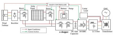
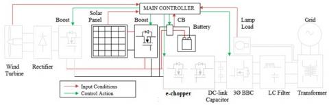
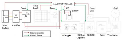
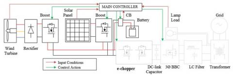
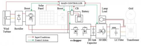
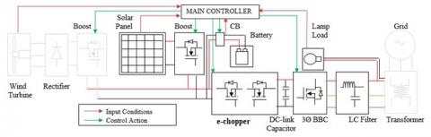
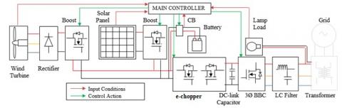
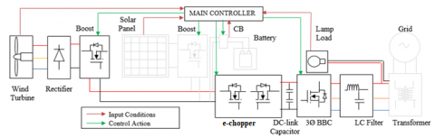
Solar and Wind sources are the utmost obtainable non-renewable energy sources; these can balance the universal power requirement [5]. These energies are unstable in nature, which are make to stable, by using regulator, voltage from the energy are not stable so a boost converter needed for conversion and step-up process maintain output voltage as constant and suitable, Permananent magnet synchronous generator coupled with wind turbine for Wind energy conversion process [6]. Solar energy is the mostly available energy from the world, electrical equivalent of available solar is 5460 times more than the global demand [7]. Three types of solar cells are available to convert solar energy into electrical which are mono-crystalline, poly-crystalline and thin film, poly-crystalline output efficiency is more than the other solar types [8]. Both wind energy conversion process and solar energy conversion process are combines in a DC bus, this common DC bus voltage is connected together which are input to the over all systems, e-chopper conversion have boost regulator which are controlled by Proportional and Integral (PI) controller [9]. Overall conversion process consists of bidirectional converters in both DC-DC (e-chopper) and AC-DC/DC-AC, because renewable energy system is integrated with grid, stanalone system cannot give continuous supply to any electrical system, grid integration is must to avoid power in any system, Overall controller is required to operate the system in an efficient way, so main controller is introduced to make system as more effective. Main controller considering some parameters such as solar irradiance, wind speed, battery state of charge and load position. According to the status of the input devices and storage devices overall operation can be controlled in an effective manner. The system behaviour may be depends internal parameters, so control from a single controller is more reliable than the different controllers, so main controller role is very important for the overall operation in all the aspects [10]. Iram Akthar et.al have suggested a Current Injected Control Loop (CICL) for the improvement of the dynamic behavior of microgrid, owing to a change in solar irradiance and wind velocity, which creates DC bus voltage oscillation as well as affects the operation of proper system [11]. Therefore manage the system in a better regulating manner, it needs a controller with better control arrangement [12]. Hence, in order to avoid power interruption, stable operation of the stand-alone system requires an effective energy storage system as well as grid integration for effective utilization of the whole system [13]. Aim of this research is to make clean and green environment in order to control air pollution [14]. Main controller based system may increase system reliability. Arrangement of efficient energy storage electrical system is represented in Figure 1. Proposed methodology enhances the constant output voltage of BBC with less amount of ripple content for various modes of operation, when comparing the conventional methods of control strategies of grid interfaced [15] renewable energy systems.
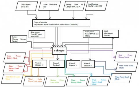
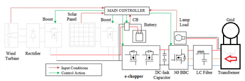
Solar power is the most widely available source, when the wind energy is not existing as the wind velocity v = 0 m/s, then system operates in mode-1. When Solar power is unavailable, then wind power is the only existing one, as wind velocity v > 5 m/s, then system operates in mode-2. If both sources are available, system acquire both supply else only one at a time, which makes more comfortable in all thee aspects, modes of operation should convenient, comfortable and controllable. Velocity of wind is measuring by means of anemometer, wind speed is converted to electrical by means of WECS, cut-in voltage and cut-out voltage depends specification of the turbine, system imports supply to grid, else it continues standalone mode is as shown in Figure 2.
Figure 1. Illustration of an efficient electrical system
Figure 2. Modes of operation based on Main controller
2.1 Operating modes (1-3) of solar, wind and wind-solar power battery
Solar power is the most widely available source, when the wind energy is not existing as the wind velocity v = 0 m/s, then system operates in mode-1 is as shown in Figure 3a. When Solar power is unavailable, then wind power is the only existing one, as wind velocity v > 5 m/s, then system operates in mode-2 is shown in Figure 3b. If two sources are available, then battery gets charging from these sources. If both sources are available, system acquire both supply else only one at a time, which makes more comfortable in all thee aspects. Velocity of wind is measuring by means of anemometer, wind speed is converted to electrical by means of WECS, cut-in voltage and cut-out voltage depends specification of the turbine, system imports supply to grid shown in Figure 3c. Eq. (1) indicates the generation of Electrical energy from wind power, Eq. (2) indicates rectifier output of Wind Energy Conversion System (WECS). When Solar power is unavailable, then wind power is the only existing one, as wind velocity v > 5 m/s, then system operates in mode-2.
$P_{e}=\frac{1}{2} C_{p}(\beta, \lambda) \rho A u^{3}$ (1)
WECS (Vr) is represented in Eq. (7) from PMSG output,
$V_{r}=\frac{3 V_{m}}{\pi}(1+\cos \alpha)$ (2)
Eq. (3) indicates wind boost output voltage (Vbw), it is equal to the output of case (i) where Vo is open circuit voltage.
$V_{b w}=V_{0}\left(\frac{1}{1-D}\right)$ (3)
2.2 Operating modes (4-6) of solar, wind and solar- wind power battery-load
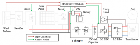
Wind energy also available source, which is second source to the system from renewable source, when solar energy is not available during cloudy days and night time, then system operates Solar source battery mode which supplies to battery as well as load or mode-4 is as shown in Figure 3d. During wind power is unavailable, then solar power is the only available source, then system operates in mode-5 or wind source battery mode which supplies to battery as well as load is shown in Figure 3e. During availability of both the sources, energy storage device charging from wind and solar energies. If both sources are available then Solar and wind source battery-load mode which supplies to battery as well as load, or mode 6, if load is in off state system exports supply to grid shown in Figure 3f. Eq. (4) indicates the generation of power from solar power, current equation is in Eq. (5) indicates Id from solar energy conversion system (SECS).
Output current of photovoltaic (Ish) is given in Eq. (6).
$I_{0}=I_{L}-\left(I_{d}-I_{s h}\right)$ (4)
$I_{d}=I_{o}\left(\exp \left[\frac{q V_{o}+R_{s e} I_{o}}{K T_{k}}\right]-1\right)$ (5)
$I_{s h}=\frac{\left(V_{o}+R_{s e} I_{o}\right)}{R_{s h}}$ (6)
2.3 Operating modes (7-8) of solar, wind and solar- wind power load
In these source circumstances of modes 7 and 8 be alike to modes 1, 4 as well as 2, 5. Solar power is the most widely available source, when the wind energy is not existing as the wind velocity v = 0 m/s, then system operates in mode-7 is as shown in Figure 3g. When Solar power is unavailable, then wind power is the only Figure 3h.
The electrical system is efficient or effective during closed-loop pattern. Mode 9 and 10 are shown in the Figures 3i and 3j.
Eq. (7) indicates the output of solar fed boost mode (Vbs) and also output of case (2) all the ten modes are explained in Figure 3.
$V_{b s}=V_{r}\left(\frac{1}{1-D}\right)$ (7)
Eq. (8) indicates the input charge of battery.
$Q_{e}=Q_{e_{-} i n i t}+\int-I_{m}(\tau) d t$ (8)
a. Mode 1 or solar source battery charging mode
b. Mode 2 or wind source battery charging mode
c. Mode 3 or Solar-wind source battery charging mode
d. Mode 4 or wind source battery charging-load mode
e. Mode 5 or solar source battery charging-load mode
f. mode-6 or solar-wind source battery charging-load mode
g. Mode 7 or Wind source load mode
h. Mode 8 or solar source load mode
i. Mode 9 or Buck mode
j. Mode 10 Battery source load mode
Figure 3. Ten modes of operation
2.4 Design of PID controller
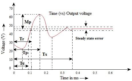
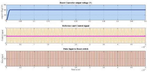
In the time domain control system involves essentially the evolution of steady state and transient response of the system. The transient nature of the response of a linear control system is revealed by the standard output response as shown in Figure 4. From the response characteristics initially, the curve starts from 30V of magnitude and dip at 0.05 ms at the magnitude of 24V.
Figure 4. Output of the UBC with PID
Then magnitude of voltage rises up to 60V at 0.17 ms and follows by a small dip at 0.24 ms then finally comes to steady state at 0.36 ms in a magnitude of constant 48V. From this response to the final value the time required in the first dip is called delay time TD. From the response characteristics the variations of initial value the time required for over damped &under damped and attains the final value is called rise time. The time required for the response to reach its peak value. It is defined as the time at which response undergoes the first overshoot which is always peak overshoot is called the peak time.
2.4.1 Ziegler-Nichols tuning rule
All the three controllers have separate gain, Proportional Kp, Integral Ki and Derivative Kd. All three controllers’ gains are combined and made as common gain K.
Step 1: Dynamic characteristics are determined and connected in a nested control loop.
Step 2: Tunning parameters are identified to minimize the overshoot. Stability of the system should be control, so overshoot, rise time, settling time etc., should be estimated accordingly all the three parameters should be controlled. The overall gain can be evaluated to control the system parameters. Overall gain is also called ultimate gain. This ultimate gain can alter all the parameters by set of protocol or procedure as follows:
1. Ki and Kd values to make as zero. So ultimate gain can control Kp. In some of the control process integral and derivative control should make as zero. This may control overshoot time by controlling reise time, to determine the overshoot and rise time, in order to reduce overall control gain or ultimate gain Ku.
2. Ultimate gain Ku should be recorded in the closed loop configuration of overall control process. Closed loop control of the system may maintain the control gain as unity by means of continuous control.
3. All three parameters are controlling by control ultimate gain in the zeigler-nichols tuning. Proportional, integral and derivative controller are very helpful to control overshoot, rise time and settling time in an effective manner are shown in Table 1.
Table 1. Zeigler-nichols tuning rules
|
Type of control |
Gc(s) |
Kc |
T1 |
TD |
|
P |
Kc |
Kcu |
- |
- |
|
PI |
$K_{c}+\frac{1}{T_{s}}$ |
0.45Kcu |
$\frac{T_{u}}{1-2}$ |
- |
|
PID |
$K_{c}\left(1+\frac{1}{T_{1} s}+T_{D} S\right)$ |
0.6Kcu |
$\frac{T_{u}}{2}$ |
$\frac{T_{u}}{8}$ |
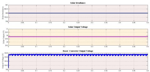
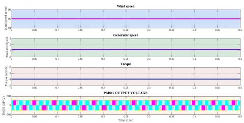
Simulation result of the overall system is evaluated with different inputs from solar and wind, solar irradiation is adjusted up to 800 irradiance, solar energy conversion system outputs are shown in Figure 5 and Figure 6 indicates solar output with different irradiance, wind speed is evaluated from 3 m/s to 11 m/s. cut in speed of wind is fixed as 5 m/s because required voltage getting at 76.5 radians/s and cut out speed is decided as 11 m/s wind energy conversion system outputs are shown in Figure 8. Voltage speed is proportional with each other. irrespective of voltage. e-chopper always maintain 110 V in the output side bidirectional boost converter output is always 230 V. this 230 V is connected to AC load or grid, which is input to the system when grid supply as input. Battery state of charge SOC is from 40% to 100%. If battery SOC = 40%, then first three modes of operation will happen, it may be sourced by either solar or wind or both solar and wind. If battery SOC is in between 40 to 100%. Next three modes of operation will happen. During modes 4 to 6 also sources may be either solar or wind or both. If battery SOC is more than 80%. Modes 7 to 10 will happen either battery or grid will supply the sources to the overall systems. During battery discharging to the load bidirectional converter acts in boost mode and battery charging from grid e-chopper acts in buck mode of operation. During these modes of operations universal controller role is most important. Because overall control is fully depending on main controller. Battery SOC So the battery is needed to charge the maximum of SOC = 40% and beyond that value the mode should be changed to next mode of operation. The duty cycles are automatically adjusted based on output due to closed operations the unidirectional output is maintained at 110 V. The output of the e-chopper is given to the charging control circuit. The supply of e-chopper is directly given to the energy storage device because the battery level is less than 40%. Specification of PMSG model is given in Table 2.
Table 2. PMSG model specification
|
Parameter |
Specifications |
|
Rated output Voltage |
415 V AC |
|
No. of Phase |
3 |
|
Rated power |
7.5 KW |
|
Rated current |
15 A |
|
No. of Rotor poles |
4 |
Figure 5. Solar energy conversion output
Figure 6. Solar boost converter output
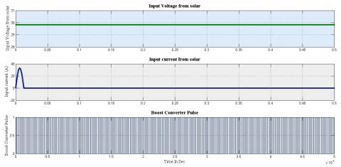
Figure 7. Boost converter output
Figure 8. Wind energy conversion output
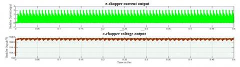
Figure 9. e-chopper output
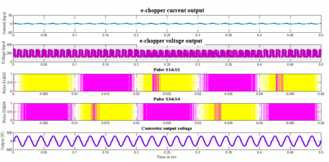
Figure 10. Bidirectional inverter output
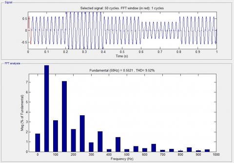
Figure 11. Bidirectional inverter current THD
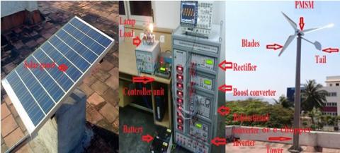
In this mode the energy storage device SOC level is in the range of (40-80) %. The control breakers allowing the supply from the unidirectional boost converter to both energy storage device and e-chopper. Boost converter always maintain 110V in the output side bidirectional boost converter output is always 230 V. this 230 V is connected to AC load or grid, which is input to the system when grid supply as input. Battery state of charge SOC is from 40% to 100%. If battery SOC = 40%, then first three modes of operation will happen, it may be sourced by either solar or wind or both solar and wind. If battery SOC is in between 40 to 100%. Next three modes of operation will happen. During modes 4 to 6 also sources may be either solar or wind or both. If battery SOC is more than 80%. Modes 7 to 10 will happen either battery or grid will supply the sources to the overall systems. During battery discharging to the load bidirectional converter acts in boost mode and battery charging from grid e-chopper acts in buck mode of operation. During these modes of operations universal controller role is most important. Because overall control is fully depending on main controller. Battery SOC So the battery is needed to charge the maximum of SOC = 40% and beyond that value the mode should be changed to next mode of operation. The duty cycles are automatically adjusted based on output due to closed operations the unidirectional output is maintained at 110 V. The output of the unidirectional boost converter is given to the charging control circuit. The output of the unidirectional boost converter is given to the charging control circuit. The supply of UBC is directly given to the energy storage device because the battery level is less than 40%. Figure 7 shows the output waveforms of the wind-solar mode electrical system. Input is getting from wind PMSG and solar-based boost mode is variable supply, thus primarily converts into DC from wind via 3ᴓ uncontrolled bridge rectifier which is as shown in Figure 9. DC voltage of bridge rectifier, as well as variable DC voltage, converts into fixed DC through boost mode in both primary sources, those boost operations are controlled by PI controller and the converter voltage is almost constant with less amount of ripple content. These constant DC is directly connected and formed as DC bus, DC power is supplied to e-chopper. In the other side, the input of boost mode is taken from DC bus and it is step up which operates as e-chopper. Again the input energy is further converted from DC-AC and to the required level which is supplied to a resistive load which is shown in the Figure 10. Whole electrical input power is directly applied to the load so Total harmonic distoration (THD) also evaluated as 9.52% which is shown in the Figure 11. All the modes of operations having different types of power flow. Figure 12 represents the hardware implementation for the proposed electrical system, moreover, outcomes are obtained in simulation through Matlab Simulink. Later designed hardware results evaluated and also validated through simulation results.
Figure 12. Hardware model
Table 3. Hardware output
|
Wind- solar energy conversion |
Electrical system integrated with grid |
||||||||||
|
Modes Of Operation |
Solar PV Output (V) |
Wind velocity (m/s) |
PMSG Output (V) |
Rectifier Output (V) |
UDC Output (V) |
Battery Output (V) |
Battery SOC (%) |
e-chopper Output (V) |
Inverter Output (V) |
Load Position (s) |
Inverter/ Rectifier Mode |
|
Mode-1 |
8.1 |
6.5 |
15.2 |
13.8 |
23.9 |
24.0 |
35 |
0 |
0 |
OFF |
Stand-alone |
|
Mode-2 |
13.2 |
5.6 |
13.2 |
12.1 |
23.7 |
23.9 |
36 |
0 |
0 |
ON |
Grid-Inverter |
|
Mode-3 |
14.0 |
6.3 |
15.1 |
13.8 |
23.7 |
23.8 |
38 |
0 |
0 |
OFF |
Stand-alone |
|
Mode-4 |
9.0 |
5.8 |
13.0 |
12.0 |
23.6 |
23.9 |
65 |
47.6 |
96.7 |
ON |
Grid-Inverter |
|
Mode-5 |
14.2 |
6.2 |
14.9 |
13.8 |
23.9 |
23.6 |
71 |
47.7 |
96.0 |
ON |
Grid-Inverter |
|
Mode-6 |
13.8 |
5.9 |
15.0 |
13.7 |
23.8 |
23.8 |
75 |
47.9 |
96.0 |
OFF |
Stand-alone |
|
Mode-7 |
13.3 |
5.5 |
13.6 |
12 |
24.0 |
24.0 |
82 |
47.9 |
95.5 |
OFF |
Stand-alone |
|
Mode-8 |
13.2 |
6.73 |
15.2 |
13.7 |
23.8 |
24.0 |
81 |
47.8 |
95.9 |
ON |
Grid-Inverter |
|
Mode-9 |
6.7 |
3.8 |
8.1 |
7.1 |
23.9 |
23.9 |
77 |
47.9 |
95.8 |
ON |
Stand-alone |
|
Mode-10 |
5.9 |
3.3 |
8.0 |
7.1 |
24.0 |
23.9 |
39 |
23.9 |
47.6 |
ON |
Grid-Rectifier |
The overall system of the experimental platform resides boost mode along with bidirectional converter through PMSG. DSPIC30F4011 regulator through PID control configuration is used to control the performance of unidirectional boost mode and e-chopper. The ten operating modes of results validated through simulation outcomes. These outcomes are approximately equal to the simulation outcomes. Due to change of wind input, the system gets robust performance. The results performances are confirmed through simulation experimental response of the system. Table 3 represents the tentative proposal of overall structure results. Outcomes of all the modes obtained for several wind velocities of input. Simulation outcomes are roughly identical to real time output results.
Overall system operation is in closed loop, so system may not be face power failure. This closed loop configuration of system is controlled by main controller. Ten modes of operation may operate the overall system is in effective way. Proper modes of operations required to maintain effective & efficient utilization of power from both the sides of primary and secondary sources and some parametric considerations also required to control the system operation in a systematic way. Main controller (CLC) is introduced to control the modes of operation in closed loop structure. The role of CLC is played through Speed goat real time target machine, it can operate the total system in various modes of operation. The originality of the proposed methodology is Main controller. For effective utilization of available energies, this controller operates the entire scheme within closed-loop operation.
[1] Bonfiglio, A., Invernizzi, M., Labella, A., Procopio, R. (2019). Design and implementation of a variable synthetic inertia controller for wind turbine generators. IEEE Transactions on Power Systems, 34(1): 754-764. http://doi.org/10.1109/TPWRS.2018.2865958
[2] Luo, F., Ma, D. (2009). An integrated switching DC–DC converter with dual-mode pulse-train/PWM control. in IEEE Transactions on Circuits and Systems II: Express Briefs, 56(2): 152-156. http://doi.org/10.1109/TCSII.2008.2011609
[3] Su, F., Ki, W. (2008). Component-efficient multiphase switched-capacitor DC–DC converter with configurable conversion ratios for LCD driver applications. in IEEE Transactions on Circuits and Systems II: Express Briefs, 55(8): 753-757. http://doi.org/10.1109/TCSII.2008.922467
[4] Ramos, G.A., Soto-Perez, R.A., Cifuentes, J.A. (2017). A varying frequency LPV-based control strategy for three phase inverters. IEEE Transactions on Industrial Electronics, 64(9): 7599-7608. http://doi.org/10.1109/TIE.2017.2703656
[5] Al-Masri, H.M., Ehsani, M. (2016). Feasibility investigation of a hybrid on-grid wind photovoltaic retrofitting system. IEEE Transactions on Industrial Applications, 62(11): 1979-1989. http://doi.org/10.1109/IAS.2015.7356802
[6] Akhtar, I., Kirmani, S., Jamil, M. (2019). Analysis and design of a sustainable microgrid primarily powered by renewable energy sources with dynamic performance improvement. IET Renewable Power Generation, 13(7): 1024-1036. http://doi.org/10.1049/iet-rpg.2018.5117
[7] Kim, K., Cha, H., Park, S., Lee, I. (2018). A modified series-capacitor high conversion ratio DC–DC converter eliminating start-up voltage stress problem. IEEE Transactions on Power Electronics, 33(1): 8-12. http://doi.org/10.1109/TPEL.2017.2705705
[8] Luo, K., Shi, W.H., Chi, Y.N., Wu, Q.W., Wang, W.S. (2017). Stability and accuracy considerations in the design and implementation of wind turbine power hardware in the loop platform. CSEE Journal of Power and Energy Systems, 3(2): 167-175. http://doi.org/10.17775/CSEEJPES.2017.0021
[9] Narimani, M., Moschopoulos, G. (2014). An investigation on the novel use of high-power three-level converter topologies to improve light-load efficiency in low power DC/DC full-bridge converters. IEEE Transactions on Industrial Electronics, 61(10): 5690-5692. http://doi.org/10.1109/TIE.2014.2300063
[10] Bhattarai, R., Gurung, N., Kamalasadan, S. (2018). Dual mode control of a three-phase inverter using minimum variance adaptive architecture. IEEE Transactions on Industrial Electronics, 54(4): 3868-3880. http://doi.org/10.1109/TIA.2018.2826469
[11] Mortazavian, S., Shabestary, M.M., Mohamed, Y.A.R.I. (2017). Analysis and dynamic performance improvement of grid connected voltage source converters. IEEE Transactions on Power Electronics, 32(10): 8134-8149. http://doi.org/10.1109/TPEL.2016.2633994
[12] Tiwari, S.K., Sing, B., Goe, P. (2018). Design and control of autonomous wind-solar system with DFIG feeding 3-phase 4-wire loads. IEEE Transactions on Industrial Applications, 54(2): 1119-1127. http://doi.org/10.1109/TIA.2017.2780168
[13] Wu, W., Wang, H., Liu, Y., Huang, M., Blaabjerg, F. (2017). A dual-buck–boost AC/DC converter for DC nanogrid with three terminal outputs. IEEE Transactions on Industrial Electronics, 64(1): 295-299. http://doi.org/10.1109/TIE.2016.2598804
[14] Yu, Y., Mi, Z.Q., Guo, X.D., Niu, X.T., Zheng, X.J., Sun, C.J. (2018). Control design and implementation of a spiral spring energy storage system connected to a grid via PMSG. CSEE Journal of Power and Energy Systems, 4(3): 339-351. http://doi.org/10.17775/CSEEJPES.2016.00860
[15] Sang, Y.Y., Yang, B., Yao, W., Jiang, L. (2018). Design and implementation of perturbation observer-based robust passivity-based control for VSC-MTDC systems considering offshore wind power integration. IET Generation Transmission and Distribution, 12(10): 2415-2424. http://doi.org/10.1049/iet-gtd.2017.1693