Ruchen Chen | Yatong Ou | Wenhu Fang | Yinggang Shi* | Li Liu
© 2020 IIETA. This article is published by IIETA and is licensed under the CC BY 4.0 license (http://creativecommons.org/licenses/by/4.0/).
OPEN ACCESS
In mountainous regions, agricultural machinery is prone to bumping and jostling, which affects the operational accuracy and even causes accidents like rollovers. To solve these problems, this paper designs a self-balancing hydraulic platform for agricultural machinery to apply pesticide in mountainous regions. Based on MATLAB and Adams, the kinematics and dynamics of the proposed platform were simulated and analyzed in details. The kinematic simulation proves the stability of the platform and the rationality of the design parameters. Through dynamic simulation, the dynamic stress states of key components, such as cylinders and ball hinges, were identified, and the stiffness and strength of the relevant components were calculated. The simulation results further verify the validity of the platform design. On this basis, a physical prototype of the platform was designed and tested at ten different slopes. The test results indicate that that the platform completed leveling in 0.514s. During the levelling, the mean error and the maximum root mean square error peaked at 1.42° and 0.293°, respectively. The errors fall within the allowable range specified in the relevant national standard. Therefore, our platform has a high leveling accuracy and basically meets operational requirements. This research offers a desirable solution to the self-balancing of agricultural machinery operating in mountainous regions.
agricultural machinery, mountainous regions, self-balancing, kinematics, dynamics
A significant portion of China’s agricultural land lies in mountainous regions [1-2]. In these regions, the uneven terrain makes agricultural machinery prone to bumping and jostling, during the application of pesticides. Once the machinery bumps or jostles, the boxes of pesticide might be tipped, and the pesticide solution might be splashed, making the pesticide application unsafe, inaccurate, and non-uniform [3-5]. Therefore, the agricultural machinery should be levelled continuously during its operations in mountainous regions. To realize automatic levelling, it is necessary to detect the inclination angle of the machinery in the stationary state, calculate the amount of adjustment for chassis leveling, and integrate various mechanical, electronic, and hydraulic techniques [6-11].
Khaki and Nasiri [12] designed a leveling system based on neural network recognition, integrated the system into an adaptive neural controller, and verified its effectiveness through a levelling test of aircraft inertial navigation unit. Papadopoulos et al. [13] proposed an electromechanical-hydraulic integrated leveling technique, which greatly improves the maneuverability and safety of heavy-duty cranes. Drawing on the principle of profiling locomotion, Wang et al. [14] presented a profiling walking theory for all-terrain adaptive locomotion vehicles, calculated the key terrain adaptive parameters, and proved the stability and reliability of the theory through performance tests.
In general, traditional onboard leveling platforms are controlled by a switch-mode change valve. The common defects of these platforms include poor stability, slow response, and low precision [15, 16]. Despite the sheer number of agricultural machinery in mountainous regions of China [17, 18], there are few automatic leveling platforms suitable for pesticide application in these regions. To solve these problems, this paper designs a self-balancing hydraulic platform for agricultural machinery in mountainous regions. The platform can be installed on small agricultural machinery to ensure the self-leveling of pesticide boxes.
Based on MATLAB and Adams, simulations were carried out to analyze the kinematics and dynamics of the platform during pesticide application. Moreover, physical experiments were conducted to verify the feasibility of the platform. The agricultural machinery equipped with the platform was proved to be capable of damping the vibrations of pesticide boxes and eliminating the bumping-induced stirring or splashing of the pesticide solution.
2.1 Structure and parameters of the platform
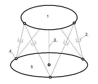
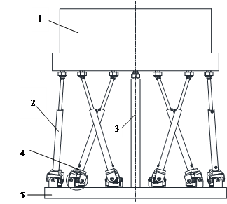
Based on Landsberger’s 3DOF robot structure, this paper designs a 6DOF self-balancing hydraulic platform. As shown in Figure 1, the platform has six hydraulic rods, forming three fulcrums each on the upper and lower planes. The fixed rods, connected by a ball hinge, limit the relative movement of the upper and lower planes, reducing the freedom of the platform. Besides, these rods at once bear the load and enhance the self-balancing compensation. A posture sensor is mounted on the lower plane, which is connected to the agricultural machinery. The sensor detects the posture of the machinery in real time, drives the six hydraulic cylinders via the hydraulic circuit, and stabilizes the upper plane, which carries the pesticide boxes, through posture adjustment. The size of the proposed platform depends on the machinery size, movement parameters, and box load. The design parameters of the proposed platform are listed in Table 1.
1. Upper plane; 2. fixed rods; 3. Central vertical rods; 4. Ball hinge; 5 Lower plane
Figure 1. The structure of the self-balancing hydraulic platform
Table 1. Design parameters of the self-balancing hydraulic platform
|
Name |
Value |
|
Radius of the upper plane |
500 mm |
|
Platform height |
800 mm |
|
Radius of the distribution circle of the upper hinge point |
500 mm |
|
Radius of the distribution circle of the lower hinge point |
550 mm |
|
Distance between the centers of the distribution circles of the upper and lower hinge points |
745 mm |
|
Distance to the long side of the upper hinge point |
707 mm |
|
Distance to the short side of the lower hinge point |
285 mm |
|
Distance to the long side of the lower hinge point |
778 mm |
|
Distance to the short side of the upper hinge point |
259 mm |
|
Height of the hinge point of the ball hinge Maximum operating angle |
55 mm 25° |
2.2 Structure and parameters of the hydraulic system
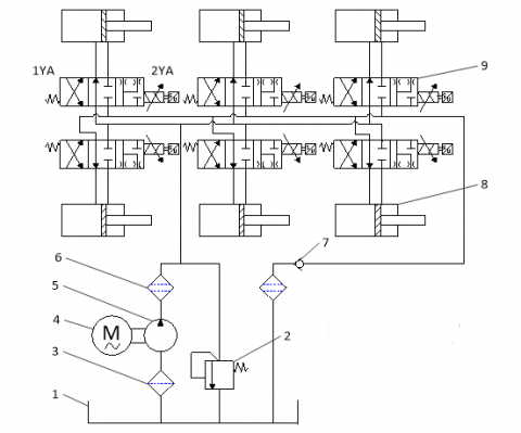
As shown in Figure 2, the hydraulic circuit relies on a symmetric valve to control the differential drive mode of the asymmetric cylinder [19]. During the operation, the constant pressure oil pump draws hydraulic oil from the oil tank, and delivers it to the electromagnetic proportional change valve (EPCV). If a cylinder needs to be extended to level the machinery, the EPCV corresponding to the cylinder will reach the right position. Then, the cylinder is differentially connected, and the hydraulic oil within the rod cavity is mixed with the fluid flowing into the rod-less cavity. In this way, the piston extends quickly, fulfilling the extension of the cylinder. If a cylinder needs to be contracted to level the machinery, the EPCV corresponding to the cylinder will stay in the left position. Then, the hydraulic oil in the rod-free cavity returns to the oil tank, and the oil level in the rod cavity decreases. In this way, the piston contracts quickly, completing the contraction of the cylinder. When the platform maintains its posture, the EPCV reaches the neutral position, and the oil pump maintains the pressure and bears the load. In this case, the hydraulic oil returns to the tank via the overflow valve, and the pressure of the oil circuit is determined by the overflow valve. The parameters of the hydraulic system are listed in Table 2.
1. Oil tank; 2. Overflow valve; 3. Coarse filter; 4. Motor; 5. Oil pump; 6. Fine filter; 7. One-way valve; 8. Hydraulic cylinder; 9. EPCV
Figure 2. Structure of the hydraulic system
Table 2. Design parameters of the hydraulic platform
|
Name |
Diameter of piston rod |
Piston stroke |
Maximum bearing capacity |
Maximum pressure |
|
Value |
30 mm |
450 mm |
3,000 N |
0.8MPa |
2.3 Spatial postures and positions
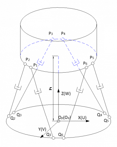
During operation, the upper plane of the self-balancing hydraulic platform remains horizontal, while the lower plane constantly changes its posture. Figure 3 shows the static coordinate system Op-XYZ and dynamic coordinate system Oq-UVW of the self-balancing hydraulic platform. Under the limitations by the fixed rods at the centers of the upper and lower planes, the translation vector of Oq-UVW relative to Op-XYZ solely depends on the three parameters of the platform position vector, which are all zero. Then, the posture of Oq-UVW relative to Op-XYZ can be expressed as:
$d=\left[\begin{array}{lll}\varphi & \theta & \psi\end{array}\right]^{T}$ (1)
Thus, the Oq-UVW can be described by the generalized coordinate vector:
$q=\left[\begin{array}{llllll}x & y & z & \varphi & \theta & \psi\end{array}\right]^{T}$ (2)
Figure 3. The static and dynamic coordinate systems of the proposed platform
The posture of Oq-UVW relative to Op-XYZ is described with the Euler angle. Taking the counterclockwise direction as positive, the Oq-UVW can be transform to Op-XYZ by three consecutive rotations: the rotation about the z-axis, followed in turn by the rotation about the y-axis, and that about the x-axis. With c=cos and s=sin, the posture transform matrix can be constructed as:
$R=R_{x(\psi)} \cdot R_{y(\theta)} \cdot R_{z(\varphi)}=\left[\begin{array}{ccc}c \theta c \varphi & -\mathrm{c} \psi \mathrm{s} \varphi+\mathrm{s} \psi s \theta c \varphi & s \psi s \varphi+c \psi s \theta c \varphi \\ c \theta s \varphi & c \psi c \varphi+s \psi s \theta s \varphi & -s \psi c \varphi+c \psi s \theta s \varphi \\ -s \theta & s \psi c \theta & c \psi c \theta\end{array}\right]$ (3)
With $E=\left[\begin{array}{ccc}1 & 0 & -\sin \theta \\ 0 & \cos \varphi & \sin \varphi \cos \theta \\ 0 & -\sin \varphi & \cos \varphi \cos \theta\end{array}\right]$, the angular velocity of the lower plane in the Oq-UVW can be described as:
$\omega=E \cdot \dot{d}$ (4)
The angular acceleration of the lower plane can be depicted as:
$\ddot{\omega}=\dot{E} \cdot \dot{d}+E \cdot \ddot{d}$ (5)
Since the compensation speed of the upper plane is small, the value of $\dot{d}$ is so small that $\dot{E} \cdot \dot{d}$ is negligible. The angular acceleration of the lower plane can be approximated as:
$\ddot{\omega}=E \cdot \ddot{d}$ (6)
According to the platform structure and the design parameters, the coordinates of each hinge point in Oq-UVW and Op-XYZ can be determined (Figure 4).
Figure 4. The coordinates of each hinge point in Oq-UVW and Op-XYZ
Let $q_{i}=\left[\begin{array}{lll}q_{i x} & q_{i y} & q_{i z}\end{array}\right]^{T}$ be the coordinate vector of the lower hinge point Qi(i=1,2,3,4,5,6) of the hydraulic cylinder in Oq-UVW. Then, the coordinate vector matrix of the lower hinge point in Oq-UVW can be described as:
$Q=\left[\begin{array}{llllll}q_{1} & q_{2} & q_{3} & q_{4} & q_{5} & q_{6}\end{array}\right]$ (7)
Let $p_{i}=\left[\begin{array}{lll}p_{i x} & p_{i y} & p_{i z}\end{array}\right]^{T}$ be the coordinate vector of the lower hinge point Pi(i=1,2,3,4,5,6) of the hydraulic cylinder in Op-XYZ. Then, the coordinate vector matrix of the lower hinge point in Op-XYZ can be described as:
$P=\left[\begin{array}{llllll}p_{1} & p_{2} & p_{3} & p_{4} & p_{5} & p_{6}\end{array}\right]$ (8)
At the center of the lower plane, a nine-axis gyro is installed to capture the real-time inclination and determine the amount of extension and contraction of the hydraulic cylinder, while keeping the balance of the upper plane. If the lower plane is tilted, the length vector of the hydraulic cylinder can be derived from the posture conversion relationship between the spatial coordinates and the length relationship between the coordinates of two points:
$s_{i}=t+R q_{i}-p_{i}(i=1,2,3,4,5,6)$ (9)
Let $s_{i}^{\prime}(i=1,2,3,4,5,6)$ be the length of the hydraulic cylinder at the current position. Then, we have:
$s_{i}^{\prime}=\sqrt{\left(t+R q_{i}-p_{i}\right)\left(t+R q_{i}-p_{i}\right)^{T}},(i=1,2,3,4,5,6)$ (10)
When the hydraulic cylinder moves from the current position to the balanced position, the hydraulic cylinders must be extended or contracted by the following amounts:
$\Delta s_{i}=s_{i}-s_{i}^{\prime}(i=1,2,3,4,5,6)$ (11)
Let $s_{i}^{\prime}=s_{0}$ be the horizontal position of the agricultural machinery, where s0 is the length of the hydraulic cylinder on the horizontal plane. At this time, each hydraulic cylinder must be extended or contracted by the same amount and kept at the neutral position.
3.1 Kinematic simulation
3.1.1 Motion modelling
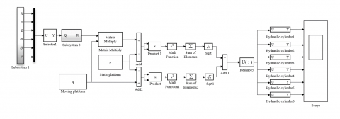
According to the above analysis, the motions of the self-balancing hydraulic platform were modelled on MATLAB/Simulink. As shown in Figure 5, the posture signals of six hydraulic cylinders were inputted via the posture signal input system (Subsystem1). The posture information was selected via the Selector module, and then transferred to the rotation transform subsystem (Subsystem3). Next, the amount of extension or contraction was calculated for the hydraulic cylinder, and displayed with an oscilloscope.
3.1.2 Simulation and results analysis
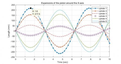
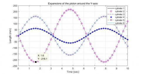
According to the spatial position and posture of the platform, the upper plane was fixed, and the motion signal of the lower plane was set to a sinusoidal signal. Then, the kinematics of the platform were simulated on Simulink. In Oq-UVW, when the lower plane rotates about the x-axis (i.e., $\varphi=(5 \pi / 36) \sin 2 \pi t, \theta=0$ and $\psi=0$), the extension and contraction of the six cylinders are detailed in Figure 6 (a). When the lower plane rotates about the y-axis (i.e., $\varphi=0, \varphi=(5 \pi / 36) \sin 2 \pi t$ and $\psi=0$), the extension and contraction of the six cylinders are detailed in Figure 6 (b).
As shown in Figure 6, when the lower plane moves sinusoidally about the x-axis or y-axis, the extension and contraction trends of three hydraulic cylinders were basically the same as the sinusoidal curve, and those of the other three were basically symmetrical with the sinusoidal curve. The trends of all cylinders were smooth. This means the self-balancing hydraulic platform runs smoothly in the course of levelling, without any movement interference. After the platform ran for 1.6s, the extension and contraction of the hydraulic cylinder peaked at 217.5mm and 218.1mm, respectively. The peak values are smaller than the designed piston stroke of 450 mm, and thus meet the design requirements.
3.2 Dynamic simulation
3.2.1 Dynamic modelling
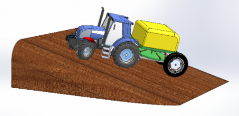
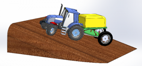
With the aid of the 3D modeling software SolidWorks, a 3D model of the self-balancing hydraulic platform was constructed based on the design parameters and relevant constraints. To ensure its correctness, the model was subjected to motion verification. Then, the platform leveling in pesticide application was simulated on agricultural machinery. The unleveled state and leveled state of the machinery are displayed in Figures 7(a) and 7(b), respectively.
Figure 5. The motion model of the self-balancing hydraulic platform
(a)Rotation about the x-axis
(b)Rotation about the y-axis
Figure 6. Extension and contraction of the piston
(a) Unleveled state
(b) Leveled state
Figure 7. The platform leveling in pesticide application
3.2.2 Simulation and results analysis
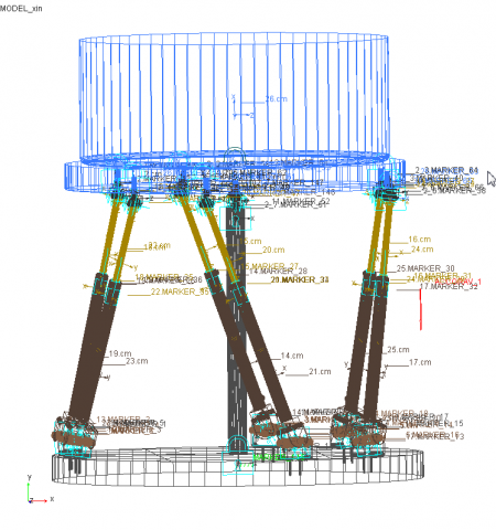
The 3D platform model was imported to Adams (Figure 8) to create a virtual prototype. Firstly, the material properties were defined: the upper and lower planes were set to cast iron, the hydraulic cylinders and hinges to cast steel, and the rotation axis of each ball hinge to 40Cr alloy steel. Then, the following constraints were added: the lower plane is connected to each cylinder by a ball hinge; the upper plane is connected to each cylinder by a ball hinge; each hydraulic cylinder is connected to its piston by a sliding pair; the intermediate rod is connected to the upper plane by a point-plane pair to eliminate redundant constraints [20]. The displacement curve obtained by MATLAB simulation was taken as the driving displacement curve (Figure 9).
Figure 8. The virtual prototype
According to the above parameters, a dynamic simulation model was configured: the number of simulation steps, 500; the simulation time, 10 seconds. Based on the displacement driving curve, the force curves of the cylinders and the ball hinges were obtained (Figures 10 and 11).
As shown in Figure 10, when t=0.76 s, the maximum extension force of cylinder 1 was 11,350 N. Considering factors like interference and starting shocks, the maximum extension force of cylinder 1 was taken as Fmax=12,100 N. Each pesticide box weighs 400kg, the cylinder works under the pressure of P1=3 MPa, the piston rod has a diameter of D=40 mm, and the rod-less cavity covers an effective area of A1=12.6 cm2. Then, we have:
$D=\sqrt{\frac{4 F_{\max }}{\pi P_{1}}}=62.1 \mathrm{mm}$ (12)
Then the diameter of the piston rod can be calculated as:
$\mathrm{d}=0.707 D=43.89 \mathrm{mm}$ (13)
Thus, the inner diameter of the cylinder is d=45 mm, and the effective operation area of the rod cavity is A2=5.5 cm2.
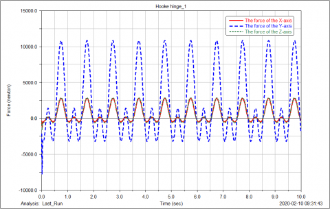
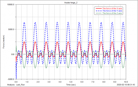
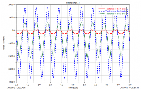
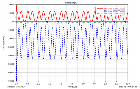
As shown in Figure 11, ball hinge 1 was subjected to a maximum binding force of 12,250.8N at 0.82 s, with the safety factor of 2. The diameter of the rotation axis of the ball hinge can be derived from the allowable shear stress:
$d_{h}=\sqrt{\frac{4 F}{2 \pi[\tau]}}=7.15 \mathrm{mm}$ (14)
Considering the working conditions of the ball hinge, the diameter of the rotation axis was determined as dh=10mm.
(a) Ball hinge 1;
(b) Ball hinge 2;
(c) Ball hinge 3;
(d) Ball hinge 4;
(e) Ball hinge 5;
(f) Ball hinge 6
Figure 11. The force curves of ball hinges
The simulation results show that the self-balancing hydraulic platform successfully leveled the agricultural machinery. Each component was found strong and stiff enough to withstand the maximum extension force of the cylinder and the maximum binding force of the ball hinge. When the y-axis is taken as the vertical direction in the coordinate system with ball hinge as the center, the average force and fluctuation of the six ball hinges in the y-direction are greater than those in the x- and z-directions. The possible reason is as follows: when the platform changes, the roll angle of the upper plane changes only a little, but the pitch angle and yaw angle change substantially. As a result, the ball hinge is subjected to greater force in the vertical direction.
Besides, the force curves of the six ball hinges were similar in shape in all directions, and all exhibited a double-peak phenomenon. This is attributable to the double-peak property of the driving displacement curve. Meanwhile, the force curve of a cylinder was continuous with that of its corresponding ball hinge, indicating that no motion shock occurred in the leveling simulation. This indirectly verifies the rationality of our platform design.
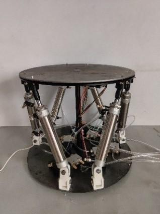
4.1 Construction of physical prototype
To verify the feasibility of the simulation results, a physical prototype of the hydraulic self-balancing platform was constructed based on the design parameters. As shown in Figure 12, the physical prototype includes a platform model, a hydraulic system model, a signal excitation system, and a control system. The key parameters of the physical prototype were fine-tuned, including the heights of the upper and lower planes, the relative position of each ball hinge, and the size of the hydraulic cylinders. For simplicity, the size of the agricultural machinery for the experiment was 0.35 times that of the original machinery, and the hydraulic cylinders were replaced with cylinders with identical performance parameters. To measure various parameters, a speed sensor was installed on each cylinder, a force sensor on each ball hinge, and a gyro on the upper plane.
Figure 12. The physical prototype
4.2 Slope leveling tests
Table 3. The results of slope leveling tests
|
Pre-test inclination |
Post-test inclination |
Mean error |
Root mean square error |
Leveling time |
||||
|
α |
β |
α |
β |
α |
β |
α |
β |
t |
|
4.98 |
0 |
0.71 |
0.01 |
0.49 |
0.01 |
0.166 |
0.008 |
0.172 |
|
5.02 |
0.02 |
0.45 |
0.01 |
0.181 |
||||
|
4.97 |
0.01 |
0.31 |
0.01 |
0.175 |
||||
|
5.04 |
5.09 |
0.75 |
0.68 |
0.55 |
0.57 |
0.149 |
0.110 |
0.235 |
|
5.07 |
5.12 |
0.39 |
0.42 |
0.239 |
||||
|
4.99 |
5.03 |
0.52 |
0.61 |
0.224 |
||||
|
9.97 |
5.16 |
1.12 |
0.74 |
0.82 |
0.67 |
0.293 |
0.062 |
0.354 |
|
10.04 |
5.17 |
0.42 |
0.69 |
0.361 |
||||
|
10.14 |
5.12 |
0.91 |
0.59 |
0.350 |
||||
|
9.98 |
10.14 |
0.92 |
0.85 |
1.09 |
0.84 |
0.125 |
0.119 |
0.463 |
|
10.12 |
10.09 |
1.15 |
0.69 |
0.493 |
||||
|
10.06 |
10.07 |
1.21 |
0.98 |
0.472 |
||||
|
15.03 |
10.08 |
0.92 |
0.85 |
1.09 |
0.84 |
0.125 |
0.119 |
0.523 |
|
15.19 |
10.09 |
1.15 |
0.69 |
0.572 |
||||
|
14.97 |
10.07 |
1.21 |
0.98 |
0.501 |
||||
|
15.36 |
15.27 |
1.28 |
1.22 |
1.27 |
1.21 |
0.078 |
0.037 |
0.612 |
|
14.68 |
15.14 |
1.36 |
1.25 |
0.596 |
||||
|
14.73 |
15.09 |
1.17 |
1.16 |
0.602 |
||||
|
20.21 |
15.31 |
1.38 |
0.89 |
1.31 |
1.10 |
0.162 |
0.150 |
0.746 |
|
19.74 |
14.83 |
1.09 |
1.23 |
0.432 |
||||
|
19.86 |
15.04 |
1.47 |
1.18 |
0.741 |
||||
|
20.21 |
15.13 |
1.38 |
0.89 |
1.31 |
1.10 |
0.162 |
0.150 |
0.856 |
|
19.74 |
14.83 |
1.09 |
1.23 |
0.828 |
||||
|
19.86 |
15.04 |
1.47 |
1.18 |
0.835 |
||||
|
24.67 |
20.03 |
1.39 |
0.98 |
1.39 |
1.18 |
0.127 |
1.145 |
0.934 |
|
24.81 |
20.17 |
1.54 |
1.32 |
0.942 |
||||
|
24.76 |
19.83 |
1.23 |
1.24 |
0.936 |
||||
|
24.52 |
24.36 |
1.29 |
1.27 |
1.42 |
1.25 |
0.106 |
0.120 |
1.233 |
|
24.69 |
24.79 |
1.42 |
1.09 |
1.356 |
||||
|
24.27 |
24.66 |
1.55 |
1.38 |
1.127 |
||||
According to Productive Testing Methods for Agricultural Machinery (GB/T 5667-2008), the physical prototype was mounted on the agricultural machinery for pesticide application at ten different slopes, aiming to test its leveling error and sensitivity to slope. Most agricultural machinery in China is suitable for farmland with slopes between 2° and 6°. If the slope falls between 6° and 15°, only small and medium-sized agricultural machinery can be implemented; if the slope falls slopes between 15° and 25°, only small agricultural machinery is applicable. Hence, the maximum slope that the platform should compensate for was set to 25° [21]. The test at each slope was repeated three times.
Considering the difficulty of finding slopes from varying angle gradients, the tests were carried out by manual simulation. The upper platform was manually adjusted to the specified angle relative to the x- and y-axes, and the inclination angle was output in real time via the angle sensor. Once the inclination angle reached a stable state, the leveling switch automatically turned the physical prototype into the equilibrium state. The leveling time was recorded immediately. The results of slope leveling tests are listed in Table 3.
As shown in Table 3, the leveling time of the physical prototype averaged at 0.603s, and the leveling errors under the ten slopes increased with the biaxial inclination angle. The mean error and the maximum root mean square error peaked at 1.42° and 0.293°, respectively. When the inclination angle of an axis increased and that angle of the other axes remained unchanged, the leveling errors were also on the rise under the coupling effect of the inclination angles of the two other axes. Within the limit of the equilibrium angle, each increase of 5° in the uniaxial inclination angle caused an error between 0° and 0.27°. The test results show that the error of the angle response fell in the range specified in GB/T 5667-2008. Hence, the proposed hydraulic self-balancing platform can properly perform the leveling function.
This paper designs a hydraulic self-balancing platform for agricultural machinery to apply pesticide in mountainous regions. The displacement, velocity and acceleration curves of the six cylinders of the platform in the leveling process were derived through kinematic simulation, which proves that the platform could run smoothly and level the machinery without any interference. Next, the dynamics of the platform were simulated to obtain the force curves and maximum extension forces of hydraulic cylinders. It was learned that the cylinders and other components (e.g. ball hinges) all met requirements. Finally, a physical prototype of the proposed platform was built and subjected to slope leveling tests. The test results show that the platform completed leveling in 0.514s. During the levelling, the mean error and the maximum root mean square error peaked at 1.42° and 0.293°, respectively. Therefore, the proposed platform can level the machinery with the slope up to 25°, providing a desirable solution to the self-balancing of agricultural machinery operating in mountainous regions.
This work was supported by Shaanxi Key Research and Development Program (Grant No.: 2019NY-171; 2018TSCXL-NY-05-04). Our thanks go to the reviewers for their helpful comments.
[1] Han, Z., Zhong, S., Ni, J., Shi, Z., Wei, C. (2019). Estimation of soil erosion to define the slope length of newly reconstructed gentle-slope lands in hilly mountainous regions. Scientific Reports, 9(1): 1-11. https://doi.org/10.1038/s41598-019-41405-9
[2] Li, S., Li, X., Sun, L., Cao, G., Fischer, G., Tramberend, S. (2018). An estimation of the extent of cropland abandonment in mountainous regions of China. Land Degradation & Development, 29(5): 1327-1342. https://doi.org/10.1002/ldr.2924
[3] Mashadi, B., Nasrolahi, H. (2009). Automatic control of a modified tractor to work on steep side slopes. Journal of Terramechanics, 46(6): 299-311. https://doi.org/10.1016/j.jterra.2009.08.006
[4] Chen, L., Karkee, M., He, L., Wei, Y., Zhang, Q. (2018). Evaluation of a leveling system for a weeding robot under field condition. IFAC-PapersOnLine, 51(17): 368-373. https://doi.org/10.1016/j.ifacol.2018.08.194
[5] Hu, L., Xu, Y., He, J., Du, P., Zhao, R., Luo, X. (2020). Design and test of tractor-attached laser-controlled rotary scraper land leveler for paddy fields. Journal of Irrigation and Drainage Engineering, 146(4): 04020002. https://doi.org/10.1061/(ASCE)IR.1943-4774.0001448
[6] Zuo, D., Qian, L., Yang, T., Cui, X., Luo, Q. (2017). Coupling leveling control based on fuzzy PID for synchronous loading system of load-bearing test bed. Chinese Journal of Electronics, 26(6): 1206-1212. https://doi.org/10.1049/cje.2017.07.016
[7] Bragard, Q., Ventresque, A., Murphy, L. (2017). Self-balancing decentralized distributed platform for urban traffic simulation. IEEE Transactions on Intelligent Transportation Systems, 18(5): 1190–1197. https://doi.org/10.1109/TITS.2016.2603171
[8] Feng, J., Gao, Q., Huang, X., Guan, W. (2016). Mathematical modeling and fuzzy control of a leveling and erecting mechanism. Automatika, 57(3): 680-690. https://doi.org/10.7305/automatika.2017.02.1490
[9] Wang, Z., Xia, Y. (2019). Model establishment of body attitude adjustment system based on Backstepping control algorithm and automatic leveling technology. Cluster Computing, 22(6): 14327-14337. https://doi.org/10.1007/s10586-018-2292-y
[10] İrsel, G., Altinbalik, M.T. (2018). Adaptation of tilt adjustment and tracking force automation system on a laser-controlled land leveling machine. Computers and Electronics in Agriculture, 150: 374-386. https://doi.org/10.1016/j.compag.2018.04.021
[11] Han, L., Yuan, Y., Zhang, J., Zhao, X., Cao, Y., Hu, Z., Zhan, D. (2013). A leveling method based on current feedback mode of scanning electrochemical microscopy. Analytical Chemistry, 85(3): 1322-1326. https://doi.org/10.1021/ac303122v
[12] Khaki, S.A., Nasiri, S.M. (2001). Leveling and gyrocompassing of stable platforms using neural networks. Iranian Journal of Science and Technology, 25(B3): 475-82.
[13] Papadopoulos, E., Mu, B., Frenette, R. (1997). Modeling and identification of an electrohydraulic articulated forestry machine. Proceedings of International Conference on Robotics and Automation. IEEE, Rome, Italy, pp. 60-65. https://doi.org/10.1109/ROBOT.1997.620016
[14] Wang, Z., Yang, J., Liu, P., Long, X., Li, H., Wei, W. (2019). Development of an agricultural vehicle levelling system based on rapid active levelling. Biosystems Engineering, 186: 337-348. https://doi.org/10.1016/j.biosystemseng.2019.08.002
[15] Kim, M.Y., Lee, C.O. (2006). An experimental study on the optimization of controller gains for an electro-hydraulic servo system using evolution strategies. Control Engineering Practice, 14(2): 137-147. https://doi.org/10.1016/j.conengprac.2005.01.010
[16] Sohl, G.A., Bobrow, J.E. (1999). Experiments and simulations on the nonlinear control of a hydraulic servosystem. IEEE Transactions on Control Systems Technology, 7(2): 238-247. https://doi.org/10.1109/87.748150
[17] Yi, Q., Chen, M., Sheng, Y., Huang, J. (2019). Mechanization services, farm productivity and institutional innovation in China. China Agricultural Economic Review, 11(3): 536-54. https://doi.org/10.1108/CAER-12-2018-0244
[18] Шуки, Ш., Цзяшэн, В., Донгвей, В. (2019). Развитие механизации сельского хозяйства в Китае и его текущая стратегическая направленность; Development of Agricultural Mechanization in China and Its Current Strategic Focus. Agricultural Machinery and Technologies, 13(3): 4-7. https://doi.org/10.22314/2073-7599-2019-13-3-4-7
[19] Chiang, M.H. (2011). A novel pitch control system for a wind turbine driven by a variable-speed pump-controlled hydraulic servo system. Mechatronics, 21(4): 753-761. https://doi.org/10.1016/j.mechatronics.2011.01.003
[20] Zhang, D., Lei, J. (2011). Kinematic analysis of a novel 3-DOF actuation redundant parallel manipulator using artificial intelligence approach. Robotics and Computer-Integrated Manufacturing, 27(1): 157-163. https://doi.org/10.1016/j.rcim.2010.07.003
[21] Wang, C., Zhen, L., Du, B.Z. (2017). Assessment of the impact of China's Sloping Land Conservation Program on regional development in a typical hilly region of the loess plateau—a case study in Guyuan. Environmental Development, 21: 66-76. https://doi.org/10.1016/j.envdev.2016.11.002