Habib Benbouhenni | Zinelaabidine Boudjema* | Abdelkader Belaidi
© 2020 IIETA. This article is published by IIETA and is licensed under the CC BY 4.0 license (http://creativecommons.org/licenses/by/4.0/).
OPEN ACCESS
Conventional direct power control (DPC) using two hysteresis comparators and switching table for a doubly fed induction generator (DFIG) integrated in a wind turbine system (WTS) have some drawbacks such as harmonic distortion of voltages, reduced robustness and powers ripples. In order to resolve these problems, a super-twisting sliding mode control (STSMC) scheme based on adaptive-network-based fuzzy inference system (ANFIS) algorithm is employed. The validity of the employed approach was tested by using Matlab/Simulink software. Interesting simulation results were obtained and remarkable advantages of the proposed strategy were exposed including simple design of the control system, reduced powers ripples as well as the other advantages.
DPC, DFIG, powers ripples, STSMC, WTS, ANFIS
The use of doubly fed induction generator (DFIG) has increased tremendously due to its easy maintenance with good reliability, low cost, and simple construction. Various control strategy for DFIG have been introduced in literatures [1-4]. Initially for the DFIG the direct power control (DPC) scheme was introduced by Takahashi in 1998 [5]. DPC has various advantages like fast response of active and reactive powers and it is simple to implement. To control the frequency and output voltage of the drives the pulse width modulation (PWM) and space vector pulse width modulation (SVPWM) switching techniques are used [6, 7]. The SVPWM technique has the ability to reduce harmonic content and low switching losses with satisfactory performance. To reduce complex online computation the intelligent techniques based SVPWM are also used [8-10]. The DSPs, FPGA, and dSPACE are used as controller platform to implement the control strategy in order to control and regulate the DFIG [11-13].
DPC strategy of control implies a direct control of the active and reactive powers which must fall into two separate certain bands to be applicable. The simple objective is to control two quantities which are the stator active and reactive powers. In DPC strategy those quantities are directly controlled by selecting the proper vector state converter. Various research papers are published on DPC scheme of permanent magnet synchronous generator (PMSG) [14, 15] and DFIG [16-18]. DPC control scheme based on an estimated stator flux has been proposed [19]. As the stator voltage is relatively harmonics free, the accuracy of the stator flux estimation can be guaranteed. However, an unfixed switching frequency is considered the main drawback of conventional DPC strategy. DPC strategy based on super-twisting sliding mode (STSM) algorithm [20]. DPC control scheme based on artificial neural networks (ANNs) of a DFIG-based wind energy system (WES) [21]. A discrete sliding mode control is designed to regulate the real and active power of DFIG-based WES [22]. Second order sliding mode control (SOSMC) and fuzzy logic controller (FLC) are combined to control DFIG [23]. DPC technique of a DFIG based-wind power generation systems by using seven-level SVPWM strategy was presented [24].
The original contribution is the application of the adaptive-network-based fuzzy inference system-STSM algorithms (ANFIS-STSM) in the DPC control with three-phase induction generator and simulation investigation of this novel control system. In this paper, the DPC system with the application of the ANFIS-STSM algorithms has been considered. based on for a DFIG-based wind turbine system (WTS) by using two-level SVPWM technique. The main advantages of the DPC-ANFIS-STSMC scheme are the simplicity to implement and the reduced ripples of active and reactive powers compared to another control schemes. The ANFIS-STSMC controller is used in order to reduce the ripple content in reactive and active powers.
In order to establish vector control of DFIG, we remind here the modeling in the Park [25, 26].
Rotor flux components:
$\left\{ \begin{align} & {{\psi }_{dr}}={{L}_{r}}{{I}_{dr}}+M{{I}_{dr}} \\ & {{\psi }_{qr}}={{L}_{r}}{{I}_{qr}}+M{{I}_{qr}} \\ \end{align} \right.$ (1)
where, Ѱdr and Ѱqr are the two components of rotor fluxes, Lr is the rotor inductance, M is the mutual inductance, Idr and Iqr are the rotor currents.
Stator flux components:
$\left\{ \begin{align} & {{\psi }_{ds}}={{L}_{s}}{{I}_{ds}}+M{{I}_{dr}} \\ & {{\psi }_{qs}}={{L}_{s}}{{I}_{qs}}+M{{I}_{qr}} \\ \end{align} \right.$ (2)
where, Ѱqs and Ѱds are the stator fluxes and Ls is the stator inductance.
Stator voltage components:
$\left\{ \begin{align} & {{V}_{ds}}={{I}_{ds}}{{R}_{s}}-{{\omega }_{s}}{{\psi }_{qs}}+\frac{d}{dt}{{\psi }_{ds}} \\ & {{V}_{qs}}={{I}_{qs}}{{R}_{s}}+{{\omega }_{s}}{{\psi }_{ds}}+\frac{d}{dt}{{\psi }_{qs}} \\ \end{align} \right.$ (3)
where, Vds and Vqs are the stator voltages, ωs is the electrical pulsation of the stator and Rs is the stator resistance.
Rotor voltage components:
$\left\{ \begin{align} & {{V}_{dr}}={{I}_{dr}}{{R}_{r}}-{{\omega }_{r}}{{\psi }_{qr}}+\frac{d}{dt}{{\psi }_{dr}} \\ & {{V}_{qr}}={{I}_{qr}}{{R}_{r}}+{{\omega }_{r}}{{\psi }_{dr}}+\frac{d}{dt}{{\psi }_{qr}} \\ \end{align} \right.$ (4)
where, Vdr and Vqr are the rotor voltages, Rr is the rotor resistance.
The stator active and reactive powers are defined as:
$\left\{ \begin{align} & {{P}_{s}}=1.5({{V}_{ds}}{{I}_{ds}}+{{V}_{qs}}{{I}_{qs}}) \\ & {{Q}_{s}}=1.5({{V}_{qs}}{{I}_{ds}}-{{V}_{ds}}{{I}_{qs}}) \\ \end{align} \right.$ (5)
where, Ps is the active power and Qs is the reactive power.
The electromagnetic torque can be written as follows:
${{T}_{e}}=\frac{3}{2}p\frac{M}{{{L}_{r}}}({{I}_{dr}}.{{\psi }_{qs}}-{{I}_{qr}}.{{\psi }_{ds}})$ (6)
where, Teis the electromagnetic torque.
p is the number of pole pairs.
The electrical model of the DFIG is completed by the following mechanical equation:
${{T}_{e}}-{{T}_{r}}=J\cdot \frac{d\Omega }{dt}+{{f}_{r}}\cdot \Omega $ (7)
where, f is the viscous friction coefficient.
J is the inertia.
Tr is the load torque.
Ω is the mechanical rotor speed.
Super twisting sliding mode controller has been widely used for control nonlinear systems. This algorithm based on the theory of variable structure systems. However, this algorithm was proposed by Utkin et al., in 1999 [27]. The STSM algorithm maintains the advantages of the traditional SMC techniques. On the other hand, this algorithm is simple and easy to implement compared to another strategies. The output signal from controller of this type is comparable with the control signal obtained from linear proportional integral (PI) controllers.
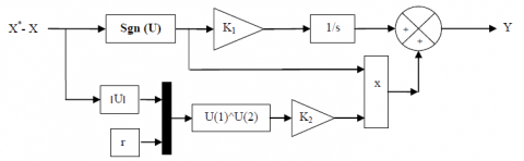
The control law of the STSM algorithm can be defined as follows:
$\left\{\begin{array}{c}u=K_{1}|S|^{r} \operatorname{sgn}(S)+u_{1} \\ \frac{d u_{1}}{d t}=K_{2} \operatorname{sgn}(S)\end{array}\right.$ (8)
where, K1 and K2 are the coefficients of the proportional and integral parts of the STSM algorithm; S is the switching function determined for the STSM algorithm, respectively; r is the exponent defined for the STSM algorithm.
The graphical representation of the control law of the STSMC algorithm is shown in Figure 1.
Figure 1. Block diagram of STSMC algorithm
The values of the K1 and K2 of all analyzed STSMC algorithm and value of the exponent r have been determined according to the procedure presented in detail in the paper [28]. The value of the exponent r has an impact on the dynamics of the control structure with STSM algorithms. This exponent can have a value between zero and one. In the analyzed control structure, its value was assumed as 0.5. The applied tuning procedure allows for ensuring the stability of the control system [29].
The procedure for determining the coefficients K1 and K2 of the STSM algorithm is based on the analysis of equations for the nonlinear control system and the equations of the output signals. These equations in the matrix form are presented as follows [30]:
$\frac{dx}{dt}=a(x,t)+b(x,t)u,\text{ }y=c\text{(}x\text{,}t\text{)}$ (9)
where, u is the vector of input control signals; x is the state vector of the system; y is the vector of output control signals; a(x, t), b(x, t) and c(x, t) are the vector functions.
The second time derivative of equations for the output signals has the matrix form presented as follows:
$\frac{{{d}^{2}}y}{d{{t}^{2}}}=A(x,t)+B(x,t)\frac{du}{dt}$ (10)
The bounds of B(x, t) and A(x, t) of the second derivative of y can be labelled as AM, Am, BM and Bm, where BM and AM are upper bounds and Am and Bm are lower bounds. The K1 and K2 are determined for all STSM algorithms according to the equations presented as follows [31]:
${{K}_{1}}>\frac{{{A}_{M}}}{{{B}_{m}}},\text{ }{{K}_{2}}\ge \frac{4{{A}_{M}}}{{{B}_{m}}^{2}}\cdot \frac{{{B}_{M}}({{K}_{1}}+{{A}_{M}})}{{{B}_{m}}({{K}_{1}}-{{A}_{M}})}$ (11)
In this work, the procedure for determining the coefficients K1 and K2 for the STSM algorithm of the DFIG has been presented. The same principle has been used to determine the values of the K1 and K2 for the STSM algorithm of the magnitude of the stator reactive and active powers used in the DPC system with three-phase DFIG.
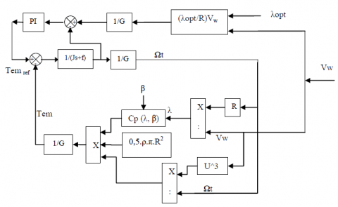
In wind turbine, the kinetic energy of wind is converted into mechanical power, the mechanical torque developed by the wind turbine is expressed by Benbouhenni et al. [32, 33]:
$\mathop{T}_{w}=\frac{\mathop{P}_{w}}{\mathop{\Omega }_{t}}=\frac{\mathop{C}_{p}(\lambda ,\beta ).\rho \pi \mathop{R}^{2}\mathop{V}_{w}^{3}}{2\mathop{\Omega }_{t}}$ (12)
where, Vw: The wind speed (m/s).
R: The radius of the turbine in (m).
Cp: The aerodynamic coefficient of power.
λ: The tip speed ratio.
β: The blade pitch angle in a pitch-controlled wind turbine.
The fundamental principle of the dynamics is applied to know the evolution of the mechanical speed.
$J\cdot \frac{d\mathop{\Omega }_{m}}{dt}=\mathop{T}_{m}-\mathop{T}_{em}-f\cdot \mathop{\Omega }_{m}$ (13)
where, J and f are the system moment of inertia and the friction coefficient respectively.
Figure 2 shows the mathematical model of the mechanical part of the wind turbine with MPPT algorithm.
In this work, the proportional-integral (PI) of the wind speed MPPT algorithm is replaced by STSM algorithm, as shown in Figure 3.
The output signal for the electromagnetic torque controller is determined by the following system of equations:
$\left\{\begin{array}{c}T_{e}^{*}=K_{P T e}\left|S_{T_{e}}\right|^{r} \operatorname{sgn}\left(S_{T e}\right)+T_{e 1}^{*} \\ \frac{d T_{e 1}^{*}}{d t}=K_{i T e} \operatorname{sgn}\left(S_{T_{e}}\right)\end{array}\right.$ (14)
where, KpTe and KiTe are the coefficients of the proportional and integral part of the STSM electromagnetic torque regulator, respectively. On the other hand, the stability of the STSM algorithm is proven using Lyapunov stability theorem.
The torque STSM algorithm gains (Ki and Kp) were found after performing simulations in Matlab/Simulink software. Table 1 shows the constants values.
Table 1. STSM controller gaines
|
Kp |
Ki |
r |
|
250000 |
10 |
0.9 |
Figure 2. Wind turbine model with the wind speed MPPT algorithm
Figure 3. MPPT with STSM algorithm
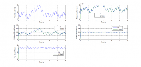
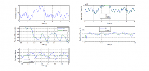
Figure 4. Wind speed
Figure 5. Mechanical power
Figure 6. Rotational speed
Figure 7. Coefficient power Cp
Figure 8. Tip speed ration
Figure 9. Zoom in the coefficient power
Figure 10. Zoom in the tip speed ration
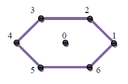
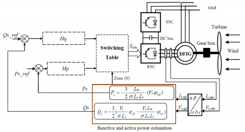
Traditional DPC scheme controls independently the stator active and reactive powers at the same time. There are six switching configurations for any selected VSI output vector, and these six switching configurations can be applied to the two-level converter to generate the same output voltage vector, as shown in Figure 11. On the other hand, the DPC control goal is to regulate the reactive and active powers of the DFIG. The traditional DPC, which is designed to control stator reactive and active powers of the DFIG, is shown in Figure 12.
The DPC performances can be ensured by using a switching table (Table 2) to select the switching voltage vector [34]. The inverter connected to the DFIG must provide the necessary complimentary frequency in order to maintain a constant stator frequency.
Figure 11. Two-level inverter vectors representations
Figure 12. Traditional DPC control
Table 2. Traditional switching table of DPC strategy
|
N |
1 |
2 |
3 |
4 |
5 |
6 |
|
|
Hq |
Hp |
||||||
|
1 |
1 |
5 |
6 |
1 |
2 |
3 |
4 |
|
0 |
7 |
0 |
7 |
0 |
7 |
0 |
|
|
-1 |
3 |
4 |
5 |
6 |
1 |
2 |
|
|
0 |
1 |
6 |
1 |
2 |
3 |
4 |
5 |
|
0 |
0 |
7 |
0 |
7 |
0 |
7 |
|
|
-1 |
2 |
3 |
4 |
5 |
6 |
1 |
|
$\left\{ \begin{matrix} \mathop{\Psi }_{s\alpha }=\int\limits_{0}^{t}{(\mathop{v}_{s\alpha }}-\mathop{R}_{s}\mathop{i}_{s\alpha })dt \\ \mathop{\Psi }_{s\beta }=\int\limits_{0}^{t}{(\mathop{v}_{s\beta }}-\mathop{R}_{s}\mathop{i}_{s\beta })dt \\\end{matrix} \right.$ (15)
The stator flux amplitude is given by:
$\mathop{\Psi }_{s}=\sqrt{\mathop{\Psi }_{s\alpha }^{2}+\mathop{\Psi }_{s\beta }^{2}}$ (16)
where,
$\left| \overline{\mathop{\Psi }_{s}} \right|=\frac{\left| \overline{\mathop{V}_{s}} \right|}{\mathop{w}_{s}}$ (17)
The stator flux angle is calculated by:
$\mathop{\theta }_{s}=arctg(\frac{\mathop{\Psi }_{s\beta }}{\mathop{\Psi }_{s\alpha }})$ (18)
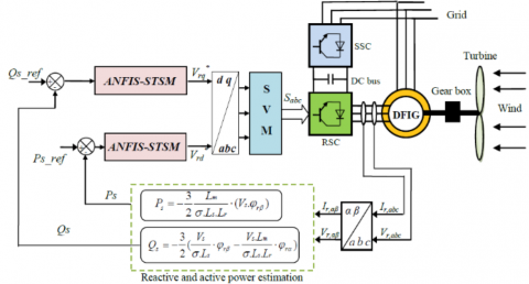
Reactive and active powers is estimated using (19) and (20) [35].
${{P}_{s}}=-\frac{3}{2}\frac{Lm}{\sigma .Ls.Lr}\cdot (Vs.{{\phi }_{r\beta }})$ (19)
${{Q}_{s}}=-\frac{3}{2}(\frac{Vs}{\sigma .Ls}\cdot {{\phi }_{r\beta }}-\frac{Vs.Lm}{\sigma .Ls.Lr}\cdot {{\phi }_{r\alpha }})$ (20)
where,
$\sigma =1-\frac{\mathop{M}^{2}}{\mathop{L}_{r}\mathop{L}_{s}}$ (21)
$\mathop{\Psi }_{s\alpha }=\sigma \mathop{L}_{r}\mathop{I}_{r\alpha }+\frac{M}{\mathop{L}_{s}}\mathop{\Psi }_{s}$ (22)
$\mathop{\Psi }_{s\beta }=\sigma \mathop{L}_{r}\mathop{I}_{r\beta }$ (23)
The reactive and active powers can be reformulated by inducing angle λ between the rotor and stator vectors as follows [36]:
${{P}_{s}}=-\frac{3}{2}\frac{Lm}{\sigma .Ls.Lr}\mathop{w}_{s}\left| \mathop{\psi }_{s} \right|\left| \mathop{\psi }_{r} \right|\sin (\lambda )$ (24)
${{Q}_{s}}=-\frac{3}{2}\frac{ws}{\sigma .Ls}\left| \mathop{\psi }_{s} \right|(\frac{M}{\mathop{L}_{r}}\left| \mathop{\psi }_{r} \right|\cos (\lambda )-\left| \mathop{\psi }_{s} \right|)$ (25)
The derivation of the active and reactive powers can give by:
$\frac{d{{P}_{s}}}{dt}=-\frac{3}{2}\frac{Lm}{\sigma .Ls.Lr}\mathop{w}_{s}\left| \mathop{\psi }_{s} \right|\frac{d(\left| \mathop{\psi }_{r} \right|\sin (\lambda ))}{dt}$ (26)
$\frac{d{{Q}_{s}}}{dt}=-\frac{3}{2}\frac{M.ws}{\sigma .\mathop{L}_{r}Ls}\left| \mathop{\psi }_{s} \right|(\frac{d(\left| \mathop{\psi }_{r} \right|\cos (\lambda ))}{dt})$ (27)
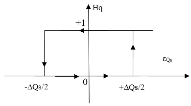
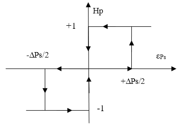
A two-level hysteresis comparator is used for reactive error (see Figure 13). For stator active power error, the hysteresis comparator used is three level as shown in Figure 14.
Figure 13. Reactive power hysteresis comparator
Figure 14. Active power hysteresis comparator
The DPC strategy of three-phase DFIG with the application of ANFIS-STSM algorithm is shown in Figure 15. In this control system, the stator reactive and stator active powers are controlled by the ANFIS-STSM algorithms.
Figure 15. DPC system of three-phase DFIG with the application of ANFIS-STSM algorithm
In the outer control loop of the stator active, the reference value of the magnitude of the stator active is compared with the estimated value. The switching function for stator active vector controller can be specified as follows:
$\mathop{S}_{\mathop{P}_{s}}=\mathop{\mathop{P}_{s}}_{ref}-\mathop{P}_{s}$ (28)
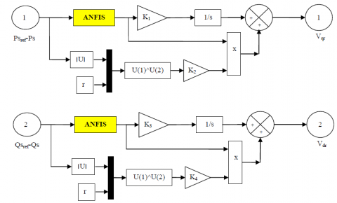
The output signal from the controller of the magnitude of the stator active vector is determined by the following system of equations:
$\left\{\begin{aligned} V_{q r}^{*}=& K_{1}\left|S_{P_{S}}\right|^{0.5} \operatorname{sgn}\left(S_{P_{S}}\right)+V_{q r 1}^{*} \\ & \frac{d V_{q r}^{*}}{d t}=K_{2} \operatorname{sgn}\left(S_{P_{S}}\right) \end{aligned}\right.$ (29)
where, K1 and K2 are the coefficients of the proportional and integral part of the STSM active power controller, respectively.
In the outer control loop of the stator reactive vector, the reference value of the magnitude of the stator reactive vector is compared with the estimated value. The switching function for stator reactive vector controller can be specified as follows:
$\mathop{S}_{\mathop{Q}_{s}}=\mathop{\mathop{Q}_{s}}_{ref}-\mathop{Q}_{s}$ (30)
This controller determines the reference component V*dr of reactive power vector, which is responsible for the control of the magnitude of the stator reactive vector. The output signal from the controller of the magnitude of the stator reactive power vector is determined by the following system of equations:
$\left\{\begin{array}{c}V_{d r}^{*}=K_{3}\left|S_{Q_{S}}\right|^{0.5} \operatorname{sgn}\left(S_{Q_{S}}\right)+V_{d r 1}^{*} \\ \frac{d V_{d r}^{*}}{d t}=K_{4} \operatorname{sgn}\left(S_{Q_{S}}\right)\end{array}\right.$ (31)
where, K3 and K4 are the coefficients of the STSM stator reactive power controller, respectively.
The reference values V*dr and V*qr are transformed to the α-β coordinate system and given to the SVM, which sets the switching states of the three-phase VSI converter.
The instantaneous magnitude of the stator active power vector and the instantaneous of the stator reactive power vector are determined by the active and reactive estimator. The vector of the rotor flux has been estimated by the current model of the DFIG based on the measured stator currents and measured voltages.
The disadvantage of STSM algorithms of the DFIG is that the active power ripple, electromagnetic torque ripple, reactive power ripple, and harmonic distortion of stator current.
In order to improve the STSM algorithms performances, a complimentary use of the ANFIS controller is proposed. The main goal of this work is to control independently the reactive and active powers both of them using the ANFIS-STSM algorithms.
ANFIS algorithm is a technology based on engineering experience and observations. ANFIS architecture was first proposed by Jang [37] in 1993. This strategy is a widely applied artificial intelligent that combines the advantages of both ANN controller and fuzzy logic (FL) it is generally used for nonlinear and complex systems in various fields [38, 39]. Garcia et al. [40] designed an ANFIS based energy management system which consists of battery, renewable energy sources and hydrogen. Hysteresis comparator based on ANFIS controllers was proposed to control induction motor (IM) [41]. ANFIS controller were designed to regulate the speed of IM controlled by direct torque control (DTC) [42]. Vector control scheme based on neuro-fuzzy was proposed to control DFIG-based wind turbine systems [43]. A novel rotor current controller based on ANFIS controllers is developed to control DFIG [44]. The ANFIS controllers-based control scheme is developed for standalone operation mode of DFIG [45]. SMC and ANFIS controllers are combined to control the DFIG-based wind energy conversion systems [46]. ANFIS-SOSMC controllers is proposed to regulate the reactive and active power of the DFIG [47]. A new nonlinear control has been proposed in this paper. This proposed nonlinear control is based on ANFIS algorithm and STSM control theory.
The ANFIS-STSM algorithms is a modification of the STSMC algorithms, where the switching controller term sgn(S(x)), has been replaced by an ANFIS controller as shown in Figure 16. Both of them do not need advanced mathematical models.The DPC with ANFIS-STSM algorithms goal is to control the stator reactive and the active powers of the DFIG. The stator reactive power is controlled by the direct axis voltage Vdr, while the active power is controlled by the quadrature axis voltage Vqr .
Figure 16. Block diagram of ANFIS-STSM algorithms
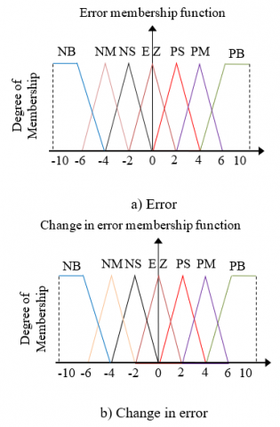
The ANFIS rules for the proposed system are given in Table 3 [48-50]. The membership function definition is shown in Figure 17. We use the next designations for membership functions:
NB: Negative Big.
NM: Negative Middle.
NS: Negative Small.
PS: Positive Small.
PB: Positive Big.
EZ: Equal Zero.
PM: Positive Middle.
Table 3. ANFIS ruls
|
e |
NB |
NM |
NS |
EZ |
PS |
PM |
PB |
|
∆e |
|||||||
|
NB |
NB |
NB |
NB |
NB |
NM |
NS |
EZ |
|
NM |
NB |
NB |
NB |
NM |
NS |
EZ |
PS |
|
NS |
NB |
NB |
NM |
NS |
EZ |
PS |
PM |
|
EZ |
NB |
NM |
NS |
EZ |
PS |
PM |
PB |
|
PS |
NM |
NS |
EZ |
PS |
PM |
PB |
PB |
|
PM |
NS |
EZ |
PS |
PM |
PB |
PB |
PB |
|
PB |
EZ |
PS |
PM |
PB |
PB |
PB |
PB |
The simulation results of DPC with ANFIS-STSM algorithms of the DFIG are compared with conventional DPC control scheme. For this end, the control system was tested under different tests.
The DFIG used in our study has the following parameters: nominal active power of the stator: Psn=1.5 MW, stator voltage: 380/696V, two poles, stator voltage frequency: 50Hz; Rs=0.012 Ω, Rr=0.021 Ω, Ls=0.0137H, Lr=0.0136H, Lm=0.0135H, J=1000 kg.m2 and fr=0.0024 Nm/s [51, 52].
Figure 17. Membership functions
A. Reference tracking test (RTT)
Figures 18-19 show the stator current THD of DFIG-based WTS obtained using FFT (Fast Fourier Transform) strategy for DPC control scheme with ANFIS-STSM algorithms (DPC-ANFIS-STSM) and conventional DPC respectively. It can be clearly observed that the THD is minimized for DPC-ANFIS-STSM control scheme (THD=0.29%) when compared to traditional DPC (THD=0.88%). Table 4 shows the comparative analysis of THD values.
Table 4. Comparative analysis of THD value
|
|
THD (%) |
|
|
DPC |
DPC-ANFIS-STSM |
|
|
Stator current |
0.88 |
0.29 |
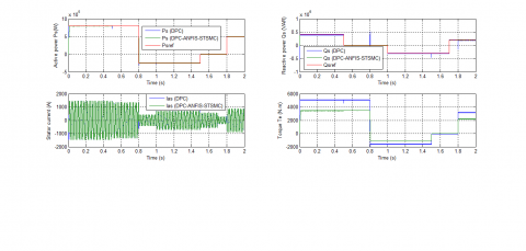
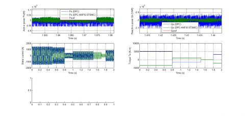
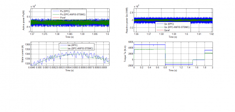
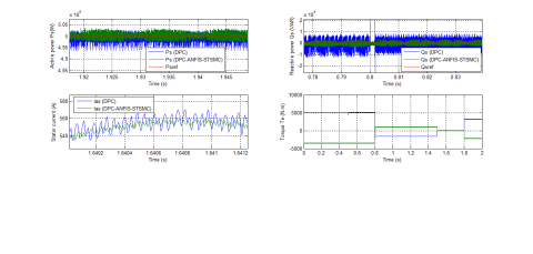
The simulation waveforms of the reference and measured active power of the DFIG-based WTS are shown in Figure 20 in order to compare the performance of the DPC system with application of the ANFIS-STSM algorithms with the performance of the conventional DPC system with application of the switching table. The active power tracks almost perfectly their reference value (Ps-ref ). On the other hand, the amplitudes of the oscillations of the active power are smaller and occur in a shorter time period in comparison with the oscillations obtained for the conventional DPC with hysteresis comparators (see Figure 23).
For the DPC-ANFIS-STSM and conventional DPC control scheme, the reactive power track almost perfectly their reference value (see Figure 21). Moreover, the DPC-ANFIS-STSM control scheme minimized the reactive power ripple compared to the conventional DPC control scheme (See Figure 24).
The trajectory of the measured magnitude of the stator current is shown in Figure 22. It can be stated that the amplitudes of the stator currents depend on the state of the drive system and the value of the load active/reactive power of the DFIG-based WTS. In addition, the DPC-ANFIS-STSM method reduced the stator current ripple compared to the DPC strategy (See Figure 25).
Figure 19. Spectrum harmonic of stator current (DPC-ANFIS-STSM)
Figure 20. Active power (RTT)
Figure 21. Reactive power (RTT)
Figure 22. Stator current (RTT)
Figure 23. Zoom in the active power (RTT)
Figure 24. Zoom in the reactive power (RTT)
Figure 25. Zoom in the stator current (RTT)
B. Robustness test (RT)
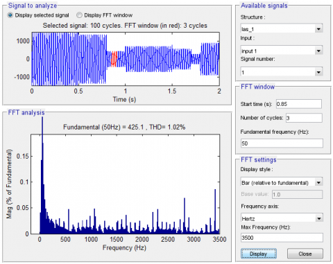
Figure 26. Spectrum harmonic of stator current (DPC)
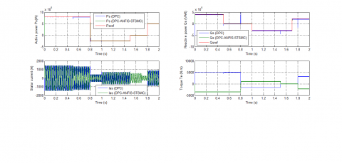
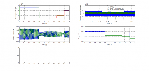
In this section, the nominal values of Rr and Rs are multiplied by 2. Simulation results are presented in Figures 26-30. As it’s shown by these figures, these variations present an apparent effect on stator powers and currents curves such as the effect appears more significant for the conventional DPC control scheme compared to DPC-ANFIS-STSM (See Figures 31-33).
Figure 27. Spectrum harmonic of stator current (DPC-ANFIS-STSM)
Figure 28. Active power (RT)
Figure 29. Reactive power (RT)
Figure 30. Stator current (RT)
Figure 31. Zoom in the active power (RT)
Figure 32. Zoom in the reactive power (RT)
Figure 33. Zoom in the stator current (RT)
The THD value of stator current in the DPC-ANFIS-STSM control scheme has been minimized significantly (See Figures 26-27). Table 5 shows the comparative analysis of THD values. Thus, it can be concluded that the proposed DPC with ANFIS-STSM algorithms is more robust than the conventional DPC control scheme.
Table 5. Comparative analysis of THD value (RT)
|
|
THD (%) |
|
|
DPC |
DPC-ANFIS-STSM |
|
|
Stator current |
1.02 |
0.46 |
The main objective of this work was to develop an improved DPC control of a DFIG integrated into a wind energy system. The basic idea was to use ANFIS-STSM hybrid controllers associated with a DPC-SVM strategy. Numerical simulations by Matlab/ Simulink have been developed to test the performances provided by the techniques used. The results of simulation obtained show well the superiority of the proposed technique (DPC-ANFIS-STSM) compared to the classical one (DPC) especially in the attenuation of the fluctuations of the powers supplied and the robustness against parametric variations.
|
STSM |
Super-twisting sliding mode |
|
DPC |
Direct power control |
|
DFIG SVPWM |
Doubly fed induction generator Space vector pulse width modulation |
|
ANFIS NPC ANN FLC GSC SOSMC PI r, s d, q SVM Lr, Ls Lm Rr, Rs ѱr, ѱs Is, Ir Vs, Vr Ps, Qs |
Adaptive Network-Based Fuzzy Inference System Neutral point clamped Artificial neural network Fuzzy logic controller Grid side converter Second order sliding mode controller Proportional-integral Rotor, stator Synchronous d-q axis Space vector modulation Stator and rotor self-inductances Mutual inductance Stator and rotor resistances Rotor and Stator flux vectors Rotor and stator current vectors Rotor and stator voltage vectors Active and reactive powers |
1. The coefficients of the STSM stator active/reactive power controllers
Table 6 shows the constants values of the reactive/active power STSM algorithm gains (K1, K2, K3 and K4).
Table 6. STSM controller gaines
|
Reactive power |
Active power |
||||
|
K3 |
K4 |
r |
K1 |
K2 |
r |
|
200 |
1000 |
0.5 |
200 |
1000 |
0.5 |
The block diagram of ANFIS controller is shown in Figure 34.
Figure 34. ANFIS controller
The structure of the ANN controller is illustrated in the Figure 35. The block diagram of layer 1 and layer 2 is shown in Figure 36 and Figure 37 respectively.
Figure 35. Block diagram of the ANN controller
Figure 36. Layer 1
Figure 37. Layer 2
[1] Tavakoli, S.M., Pourmina, M.A., Zolghadri, M.R. (2013). Comparison between different DPC methods applied to DFIG wind turbines. International Journal of Renewable Energy Research, 3(2): 446-452. https://www.ijrer-net.ijrer.org/index.php/ijrer/article/view/680/pdf
[2] Benbouhenni, H. (2019). Application of seven-level neural space vector PWM in direct vector control system of doubly fed induction generator for wind turbine. International Journal of Smart Grid, 3(3): 163-171.
[3] Fihakhir, A.M., Bouhamida, M. (2016). Nonlinear control of a doubly fed induction generator driven wind turbine. Electrotehnica Electronica Automatica (EEA), 64(2): 23-30. https://doi.org/10.1016/j.ijepes.2018.03.012
[4] Izanlo, A., Gholamian, S.A., Kazemi, M.V. (2017). Comparative study between two sensorless methods for direct power control of doubly fed induction generator. Rev. Roum. Sci. Techn.-Electrotechn. Et Energ, 62(4): 358-364. http://www.revue.elth.pub.ro/viewpdf.php?id=703
[5] Benbouhenni, H. (2019). Comparison study between SVPWM and FSVPWM strategy in fuzzy second order sliding mode control of a DFIG-based wind turbine. Carpathian Journal of Electronic and Computer Engineering, 12(2): 1-10.
[6] Massoum, S., Meroufel, A., Massoum, A., Wira, P. (2019). A direct power control of the doubly-fed induction generator based on the SVM strategy. Elektrotehniski Vestnik, 45(5): 235-240. https://ev.fe.uni-lj.si/5-2017/Massoum.pdf
[7] Benbouhenni, H., Boudjema, Z., Belaidi, A. (2019). Using four-level NSVM technique to improve DVC control of a DFIG based wind turbine systems. Periodica Polytechnica Electrical Engineering and Computer Science, 63(3): 144–150. https://doi.org/10.3311/PPee.13636.
[8] Benbouhenni, H., Boudjema, Z., Belaidi, A. (2018). Neuro-second order sliding mode control of a DFIG supplied by a two-level NSVM inverter for wind turbine system. Iranian Journal of Electrical and Electronic Engineering, 14(4): 362-373. https://doi.org/10.22068/IJEEE.14.4.362
[9] Benbouhenni, H., Boudjema, Z., Belaidi, A. (2018). A comparative study between four-level NSVM and three-level NSVM technique for a DFIG-based WECSs controlled by indirect vector control. Carpathian Journal of Electronic and Computer Engineering, 11(2): 13-19. http://cjece.ubm.ro/vol/11-2018/2/03-cjece-2018-0002.pdf
[10] Tremblay, E., Atayde, S., Chandra, A. (2011). Comparative study of control strategies for the doubly fed induction generator in wind energy conversion systems: A DSP-based implementation approach. IEEE Transactions on Sustainable Energy, 2(3): 288-299. https://doi.org/10.1109/tste.2011.2113381
[11] Kadri, A., Marzougui, H., Bacha, F. (2019). Implementation of direct power control based on stator flux estimation using low-pass filter estimator for doubly fed induction generator–wind energy conversion system. SAGE Journals, 233(7): 764-778. https://doi.org/10.1177/0959651818818895
[12] Dzung, P.Q., Bao, A.N., Minh, P.L., Dinh, H.H. Lee, H.H. (2011). The implementation of direct virtual torque control and direct power control for DFIG in wind energy system using dSPACE 1103. IEEE PEDS 2011, Singapore, pp. 5-8. https://www.academia.edu/7818849/The_implementation_of_direct_virtual_torque_control_and_direct_power_control_for_DFIG_in_wind_energy_system_using_DSpace_1103?auto=download
[13] Tiwaria, R., Kumar, Ka., Ramesh, N.B., Prabhu, K.R. (2018). Coordinated MPPT and DPC strategies for PMSG based grid connected wind energy conversion system. Energy Procedia, 145: 339–344. https://doi.org/10.1016/j.egypro.2018.04.061
[14] Jain, A., Shankar, S., Vanitha, V. (2018). Power generation using permanent magnet synchronous generator (PMSG) based variable speed wind energy conversion system (WECS): An overview. Journal of Green Engineering, 74: 477–504. https://doi.org/10.13052/jge1904-4720.742
[15] Amrane, F., Chaiba, A. (2016). A novel direct power control for grid-connected doubly fed induction generator based on hybrid artificial intelligent control with space vector modulation. Rev. Roum. Sci. Techn.-Electrotechn. Et Energ, 61(3): 263-268. https://pdfs.semanticscholar.org/b53f/ba863ad9dabbe4fab7786d3a9a1dfc0a7fd7.pdf
[16] Rao, Y.S., Laxmi, A.J. (2012). Direct torque control of doubly fed induction generator based wind turbine under voltage dips. International Journal of Advances in Engineering & Technology, 3: 711-720. https://pdfs.semanticscholar.org/7103/0e8fe94e6b7ffcbcd8967c2ed3924ca93414.pdf
[17] Kazemi, M.V., Yazdankhah, A.S., Kojabadi, H.M. (2010). Direct power control of DFIG based on discrete space vector modulation. Renewable Energy, 35: 1033-1042. https://doi.org/10.1016/j.renene.2009.09.008
[18] Benbouhenni, H., Boudjema, Z., Belaidi, A. (2019). Indirect vector control of a DFIG supplied by a two-level FSVM inverter for wind turbine system. Majlesi Journal of Electrical Engineering, 13(1): 45-54. http://mjee.iaumajlesi.ac.ir/index/index.php/ee/article/view/2693
[19] Cartwright, L. Xu, P. (2006). Direct active and reactive power control of DFIG for wind energy generation. IEEE Trans. Energy Convers, 21(3): 750-758.
[20] Bouyekni, A., Taleb, R., Boudjema, Z., Kahal, H. (2018). A second-order continuous sliding mode based on DFIG for wind-turbine-driven DFIG. Elektrotehniški Vestnik, 85(1-2): 29-36. https://ev.fe.uni-lj.si/1-2-2018/Bouyekni.pdf
[21] Benbouhenni, H. (2019). Application of five-level NPC inverter in DPC-ANN of doubly fed induction generator for wind power generation systems. International Journal of Smart Grid, 3(3): 128-137.
[22] Kairous, D., Wamkeue, R. (2012). DFIG-based fuzzy sliding-mode control of WECS with a flywheel energy storage. Electr. Power Syst. Res., 93: 16-23.
[23] Boudjema, Z., Taleb, R., Yahdou, A. (2016). A new DTC scheme using second order sliding mode and fuzzy logic of a DFIG for wind turbine system. International Journal of Advanced Computer Science and Applications, 7(8): 49-56.
[24] Benbouhenni, H. (2019). Direct power control of a DFIG fed by a seven-level inverter using SVM strategy. International Journal of Smart Grid, 3(2): 55-62.
[25] Benbouhenni, H., Boudjema, Z., Belaidi, A. (2019). Direct vector control of a DFIG supplied by an intelligent SVM inverter for wind turbine system. Iranian Journal of Electrical and Electronic Engineering, 15(1): 45-55. https://doi.org/10.22068/IJEEE.15.1.45
[26] Yaichi, I., Semmah, A., Wira, P., Djeriri, Y. (2019). Super-twisting sliding mode control of a doubly-fed induction generator based on the svm strategy. Periodica Polytechnica Electrical Engineering and Computer Science, 63(3): 178–190. https://doi.org/10.3311/PPee.13726
[27] Tayebi-Haghighi, S., Piltan, F., Kim, J.M. (2018). Robust composite high-order super-twisting sliding mode control of robot manipulators. Robotics, 7(1). https://doi.org/10.3390/robotics7010013
[28] Levant, A. (1993). Sliding order and sliding accuracy in sliding mode control. International Journal of Control, 58(6): 1247–1263. https://doi.org/10.1080/00207179308923053
[29] Listwan, J. (2018). Application of super-twisting sliding mode controllers in direct field-oriented control system of six-phase induction motor: Experimental studies. Power Electronics and Drives, 38(1). https://doi.org/10.2478/pead-2018-0013
[30] Gonzales, T., Moreno, A., Fridman, L. (2012). Variable gain super-twisting sliding mode control. IEEE Transactions on Automatic Control, 57(8): 2100–2105. https://doi.org/10.1109/TAC.2011.2179878
[31] Benbouhenni, H. (2018). Comparative study between different vector control methods applied to DFIG wind turbines. Majlesi Journal of Mechatronic Systems, 7(4). http://journals.iaumajlesi.ac.ir/ms/index/index.php/ms/article/view/382
[32] Benbouhenni, H. (2018). Fuzzy second order sliding mode controller based on three-level fuzzy space vector modulation of a DFIG for wind energy conversion systems. Majlesi Journal of Mechatronic Systems, 7(3). http://journals.iaumajlesi.ac.ir/ms/index/index.php/ms/article/view/369
[33] Jou, S., Lee, S., Park, Y., Lee, K. (2009). Direct power control of a DFIG in wind turbines to improve dynamic responses. J. Power Electron, 9(5): 781-790. http://wave.ajou.ac.kr/13_2009_09.pdf
[34] Shehata, E.G., Gerges, M., Salama, M. (2013). Direct power control of DFIGs based wind energy generation systems under distorted grid voltage conditions. Electr. Power Energy Syst., 53: 956-966. https://doi.org/10.1016/j.ijepes.2013.06.006
[35] Benbouhenni, H. (2019). A novel switching tables of twelve sectors DTC for induction machine drive using artificial neural networks. Automation, Control and Intelligent Systems, 7(1): 1-8.
[36] Benbouhenni, H., Boudjema, Z., Belaidi, A. (2020). Power ripple reduction of DPC DFIG drive using ANN controller. Acta Electrotechnica et Informatica, 20(1).
[37] Jang, J.S.R. (1993). ANFIS: Adaptive-network-based fuzzy inference system. IEEE Transactions on Systems Man & Cybernetics, 23: 665-685. https://doi.org/10.1109/21.256541.
[38] Melin, P., Castillo, O. (2001). Intelligent control of complex electrochemical systems with a neuro-fuzzy-genetic approach. IEEE Trans. Industrial Electronics, 48(5): 951-955. https://doi.org/10.1109/41.954559
[39] Sun, Y., Xu, J., Qiang, H., Lin, G. (2019). Adaptive neural-fuzzy robust position control scheme for Maglev train systems with experimental verification. IEEE Trans. on Industrial Electronics, 66(11): 8589-8599.
[40] Garcia, P., Garcia, C.A., Fernandez, L.M., Llorens, F., Jurado, F. (2014). ANFIS based control of a grid-connected hybrid system integrating renewable energies, hydrogen and batteries. IEEE Transactions on Industrial Informatics, 10(2): 1107-1117.
[41] Benbouhenni, H. (2019). Fuzzy speed controller of induction machine with 36 sectors DTC based ANFIS hysteresis comparator. Majlesi Journal of Mechatronic Systems, 8(3): 1-8.
[42] Benbouhenni, H. (2019). ANFIS speed controller of IM drives with three-level DTC-based neural network. Majlesi Journal of Mechatronic Systems, 8(1): 11-17.
[43] Jabr, M. Lu, D., Narayan, C.K. (2011). Design and implementation of neuro-fuzzy vector control for wind-driven doubly induction generator. IEEE Transactions on Sustainable Energy, 2(4): 404-413.
[44] Komijani, H. (2019). ANFIS controller design of DFIG under distorted grid voltage situations. Recent Advances in Electrical & Electronic Engineering, 12(5). https://doi.org/12.2174/2352096511666180719095657
[45] Amin, J.K., Nasir Uddin, M., Marsadek, M. (2019). ANFIS based neuro-fuzzy control of DFIG for wind power generation in standalone mode. 2019 IEEE International Electric Machines & Drives Conferences (IEMDC), San Diego, CA, USA, pp. 2077-2082.
[46] Benbouhenni, H. (2020). ANFIS-sliding mode control of a DFIG supplied by a two-level SVPWM technique for wind energy conversion system. International Journal of Applied Power Engineering (IJAPE), 9(1). https://doi.org/http://doi.org/10.11591/ijape.v9.i1.pp%25p.
[47] Benbouhenni, H. (2019). Second order sliding mode with ANFIS controllers for DFIG using seven-level NSVPWM technique. Majlesi Journal of Energy Management, 8(1): 29-39.
[48] Benbouhenni, H. (2017). Comparison study between FPWM and NSVM inverter in neuro-sliding mode control of reactive and active power control of a DFIG-based wind energy. Majlesi Journal of Energy Management, 6(4). http://journals.iaumajlesi.ac.ir/em/index/index.php/em/article/view/338.
[49] Benbouhenni, H., Boudjema, Z., Belaidi, A. (2018). Using three-level fuzzy space vector modulation method to improve indirect vector control strategy of a DFIG based wind energy conversion systems. International Journal of Smart Grid, 2(3): 155-171. https://www.ijsmartgrid.org/index.php/ijsmartgridnew/article/view/15
[50] Yadlapalli, R.T., Narasipuram, R.P., Dodda, A. (2019). Development of fuzzy logic controller for improved interline unified power quality conditioner. Int. J. Innovative Computing and Applications, 10(2): 86–99. https://doi.org/10.1504/IJICA.2019.102098
[51] Benbouhenni, H., Boudjema, Z., Belaidi, A. (2017). DFIG-based wind turbine system using four-level FSVM strategy. Majlesi Journal of Energy Management, 6(3). http://journals.iaumajlesi.ac.ir/em/index/index.php/em/article/view/334
[52] Benbouhenni, H. (2019). A comparison study between fuzzy PWM and SVM inverter in NSMC control of stator active and reactive power control of a DFIG based wind turbine systems. International Journal of Applied Power Engineering (IJAPE), 8(1): 78-92. http://doi.org/10.11591/ijape.v8.i1.pp78-92