Divya Manukonda* | Srinivasa Rao Gorantla
OPEN ACCESS
The utilization of renewable energy sources has been rising from the last few years due to their enormous advantages. This paper presents the design of bladeless wind turbine utilizing the principles of the wind. It involves design of model predictive controller based maximum power point tracking system which tracks the voltage, current and power of the bladeless wind turbine. This paper also involves the design of water pumping system with the utilization of single phase induction motor and so the design of single phase inverter has been proposed. It presents the battery management system which continuously monitors the charging and discharging states of the battery based up on the power requirement. The entire system was designed and the results have been analyzed using MATLAB Simulink.
vortex bladeless wind turbine, model predictive controller, maximum power point tracking, single phase induction motor, battery management system
The day to day changes in the environment lead to look for an alternative to design a system which overcomes the global warming effect and provides a healthy life. So natural energy sources provide a better solution for the above mentioned problem. Among the several non-conventional energy sources like solar, wind, tidal, biomass, hydro energy, wind has been chosen due to its nature of [1-5] unlimited availability. But from several years there has been wind turbine which has been in usage for generating electricity using wind energy. Even it involves certain disadvantages such as necessity of higher wind speeds, higher installation costs. Due to these disadvantages, there has been lagging of wind energy usage in the area of residential applications. So, to get rid of these drawbacks, a novel wind turbine has been proposed which works on the principle of oscillatory motion instead of rotatory motion with the help of vertical cylindrical structure. To convert the oscillatory motion, transducer has been chosen due to its accuracy, reliability and efficiency.
As the wind speeds varies all the times, a controller has to be used to control the power produced due to the varying wind conditions. Maximum power point tracking [6-10] has been chosen as a controller for monitoring the system voltage, current and power. Among several power point trackers, perturb and observe tracking has been chosen which tracks the system voltage, current and power with several perturbations. During the lower wind speeds and no wind speeds conditions, there has to be a device which provides the continuous power supply reducing interruptions. Lead acid battery has been chosen as an energy storage device due to its advantages like simple in maintenance, longer life time, longer charge and discharge cycles. The single-phase induction motor has been chosen for water pumping applications [11, 12] due to its advantages like simple and rugged in construction.
The paper is organized as follows; the first section of the paper is dealing with the block diagram explanation of proposed vortex wind turbine. The second section deals with the MPPT with MPC controller and the third part discusses with the battery management system, fourth section presents the software realization of proposed system, results and discussion of the proposed system and the last part deals with the conclusion.
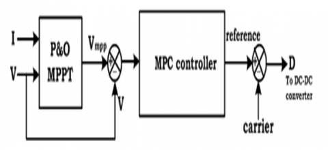
The block diagram of the proposed wind turbine is shown in below Figure 1. It consists of tapered cylindrical mast producing oscillations with the flow of wind, transducer for converting the oscillatory motions of the cylinder into electricity, rectifier for the conversion of AC power into DC power. Also, the system consists of high gain converter producing higher DC output voltage than the input voltage with lesser duty cycle. As the wind is not constant, the output power may change due to varying weather conditions, so maximum power point tracking has been designed which obtains voltage and current of the rectifier as inputs. Based up on the voltage and current values, MPPT tracker provides duty cycle for the converter to obtain the higher output voltage. The DC output of the high gain converter is fed to the single phase three level inverter which converts DC output into single phase AC output. This single-phase AC output has been fed to the single-phase induction motor for pumping the water which can be used for residential water pumping. Also, battery management controller has been used which obtains generated power and load power as inputs. Up on the comparison of the powers, battery will be charged or discharged.
Figure 1. Block diagram of the proposed water pumping system
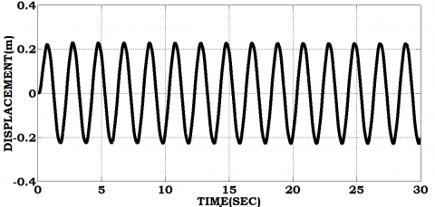
When wind passes over the mast, vortex vibrations are generated around the mast of mass M, placed on the spring of stiffness S and then it oscillates with a force of F which results the displacement of the mast. The displacement performed by the cylindrical mast can be expressed as
$D=\frac{F}{S}-\frac{M \ddot{D}}{S}$ (1)
where, S is the spring stiffness, F is the force applied on the cylindrical structure; M is the mass of the structure.
With this displacement as an input, the output will be generated across the output terminals of the transducer which can be expressed as
$\frac{V_{O}}{V_{i n}}=\frac{N_{S}}{N_{P}} C_{M}$ (2)
where, $N_{S}$ is number of turns of the secondary winding, $N_{P}$ is the number of turns of the primary winding, $C_{M}$ is the magnetic conductance.
The generated output at the output terminals of the transducer will be fed to the single-phase diode bridge rectifier whose DC output voltage can be given as
$V_{D}=\frac{2 V_{m}}{\pi}$ (3)
This DC output will be fed to the high gain-based converter whose output can be expressed as
$V_{C}=\frac{3+D}{2-2 D} V_{D}$ (4)
where, $V_{C}$ is the converter output voltage, D is the duty cycle of the converter.
This DC output from the high gain-based converter is fed to the single-phase inverter whose output voltage can be given as
$V_{I}=V_{C}$ (5)
where, $V_{I}$ is the input of the single-phase inverter which is equal to the output of the converter.
This output will be fed to the single-phase induction motor whose torque expression can be given as
$T=\frac{P}{w}$ (6)
where, T is the electromagnetic torque of the induction motor.
Where w is the speed of the motor, P is the power generated by the motor.
The output of the proposed bladeless wind turbine is not constant due to varying weather conditions, so to obtain maximum power all the times, maximum power point tracking has been designed which tracks maximum power all the times for varying weather conditions. To improve the response of the system and also to increase the efficiency of the system, model predictive controller based MPPT controller has been designed. The block diagram of proposed MPPT system is shown in below Figure 2.
Figure 2. Block diagram of the proposed MPC based MPPT controller
Model Predictive Controller:
MPC controller predicts the variation in the dependent variables of the arrangement which was occurred by the variation in the independent variables of the arrangement. In general, the independent variables that can be attuned by the controller are set points of the rigid PID controllers or the final control part. Independent variables that cannot be attuned by the controller are identified as disturbances and the dependent variables used in the arrangement are identified as control objectives or constraints. MPC controller utilizes the current system variables, present dynamic situation of the arrangement, MPC representation, targets and limits of the arrangement parameter to compute the future variation in the dependent variables.
The flow chart steps of the proposed MPC based MPPT controller is given as below:
· The voltage and current will be obtained from the wind turbine and power will be calculated
· Then change in power, change in voltage will be calculated for perturbations finding out the maximum voltage.
· This maximum voltage will be compared with the actual voltage of the turbine and the change will be fed to the MPC controller.
· This MPC controller calculates future changes based up on the present changes and then processed error will be fed for PWM generation.
The flowchart for the battery management system is shown in below Figure 3.
Figure 3. Flow chart of the battery management system
The proposed water pumping system has been simulated using MATLAB Simulink and the following are the results obtained.
The Figure 4 shows the displacement produced by the cylindrical structure with the passage of wind.
With the displacement of the structure, the core of the transducer starts moving and produces elicit whose AC voltage is shown in Figure 5.
The AC voltage of the transducer will be fed to the diode bridge rectifier which will be converted into DC voltage. This DC voltage will be fed to the high gain converter whose voltage, current and power are shown in Figures 6-8 for various wind speeds as U=0.5m/s, U=1m/s, U=1.5m/s, U=2m/s where the voltage has been increasing from zero value at t=0.2s and reaches the steady state value of 375V at t=0.7s, current has been increasing from zero value at t=0.2 s and reaches the steady state value of 7.4A at t=0.7s and also power has been increasing from zero value at t=0.2s and also reaches the steady state value of 2775W at t=0.7s.
Figure 4. Displacement of the structure
Figure 5. Output voltage of the transducer
Figure 6. Voltage of the high gain converter
Figure 7. Current of the high gain converter
Figure 8. Power of the high gain converter
The above waveforms show that even at wind speed of U=0.5m/s, the oscillatory wind turbine is able to produce certain amount of power which can be utilized for lower rating applications.
The DC voltage of the converter will be fed to the single-phase inverter which is shown in below Figure 9 whose value is around 300V.
The AC output of the inverter will be fed to the single phase induction motor whose Load Power, Speed, Torque and Currents will be Shown in below Figures 10-12.
Figure 9. Voltage of the single-phase inverter
Figure 10. Power of the load
The Figure 10 shows the power of load which is around 1000w from t=0s to t=0.6s, decreases to 200w at t=0.5s to t=0.7s, again increases to 1200W at t=2.6s. but the generated power is around zero from t=0s to t=0.2s, incrases from t=0.2s and attains the steady state value of 2775W at t=0.7s. so the power of the load is greater than the generated power from t=0s to t=0.7s, so the battery will be in discharging state from t=0s to t=0.7s, charging state from t=0.7s to t=3s.
The Figure 11 shows the response of the charging switch which opens and closes based up on the generated power and load power.
The Figure 12 shows the response of the discharging switch which opens and closes based up on the generated power and load power.
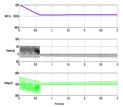
The Figure 13 shows the SOC, Voltage and current of the Battery which shows the charging and discharging state of battery with the decrease in the SOC, voltage and current.
The Figure 14 shows the parameters of the induction motor like speed of the induction motor, torque and current through the windings with the flow of input from the inverter where the speed is around 160rad/s, torque is 10N-m.
Figure 11. Pulse of the charging switch
Figure 12. Pulse of the discharging switch
Figure 13. SOC, voltage and current of the battery
Figure 14. Speed, torque and currents of single-phase induction motor
The Table 1 gives the specifications of the proposed water pumping system which includes the wind speed, rated voltage, rated speed of the system that have been consisdred for designing the system.
Table 1. Specifications of the proposed water pumping system
|
S. No |
Parameter |
Value |
|
1. |
Rated Wind speed |
2m/s |
|
2. |
Rated displacement |
0.22m |
|
3. |
Output voltage of the transducer |
50V |
|
4. |
Battery SOC |
100 |
|
5. |
Battery capacity |
10Ah |
|
6. |
Battery voltage |
300V |
|
7. |
Rated speed of the induction motor |
1500rpm |
The design of oscillatory water pumping system has been presented in this paper. The design of model predictive controller based maximum power point tracking system which tracks the voltage, current and power of the bladeless wind turbine has been presented. The design of water pumping system with the use of single-phase induction motor and so the design of single-phase inverter has been proposed. The battery management system which continuously monitors the charging and discharging states of the battery based up on the power requirement has been designed. The entire system was designed and the results are verified using MATLAB Simulink.
[1] Wu, Y.K., Tsai, C.Z., Li, Y.H. (2018). Design of wind power generators: Summary and comparison. IEEE Int. Conf. on Applied System Invention., pp. 1314-1317. https://doi.org/10.1109/icasi.2018.8394536
[2] Subramani, S., Babu, N.R. (2018). Design and development of single switch high step-up DC–DC converter. IEEE Journal of Emerging and Selected Topics in Power Electronics, Early Access, 99. https://doi.org/10.1109/JESTPE.2017.2739819
[3] Rostami, A.B., Armandei, M. (2017). Renewable energy harvesting by vortex-induced motions: Review and benchmarking of technologies. Renewable and Sustainable Energy Reviews, 70: 193-214. https://doi.org/10.1016/j.rser.2016.11.202
[4] Metry, M.M., Shadmand, M.B., Balog, R.S., Abu-Rub, H. (2017). MPPT of photovoltaic systems using sensorless current-based model predictive control. IEEE Trans. Ind. Appl., 53(2): 1157-1167. https://doi.org/10.1109/tia.2016.2623283
[5] ElShahat, A. (2016). Bladeless wind turbine as wind energy possible future technology. Natural Gas & Electricity, 33(4): 16-20. https://doi.org/10.1002/gas.21942
[6] Huang, C., Li, F.X., Jin, Z.Q. (2015). Maximum power point tracking strategy for large-scale wind generation systems considering wind turbine dynamics. 2015 IEEE Power & Energy Society General Meeting, Denver, CO, USA. https://doi.org/10.1109/pesgm.2015.7286039
[7] Kumar, A., Kochhar, E., Upamanyu, K. (2015). Photovoltaic and wind energy hybrid sourced voltage based indirect vector controlled drive for Water Pumping System. 2015 IEEE International Conference on Electrical, Computer and Communication Technologies (ICECCT), Coimbatore, India. https://doi.org/10.1109/icecct.2015.7225991
[8] Chen, X. (2014). Extreme value distribution and peak factor of crosswind response of flexible structures with nonlinear aeroelastic effect. Journal of Structural Engineering, 140(12): 04014091. https://doi.org/10.1061/(asce)st.1943-541x.0001017
[9] Shadmand, M.B., Balog, R.S., Abu-Rub, H. (2014). Model predictive control of PV sources in a smart DC distribution system: Maximum power point tracking and droop control. IEEE Trans. Energy Convers., 29(4): 913-921. https://doi.org/10.1109/tec.2014.2362934
[10] Shadmand, M., Balog, R.S., Abu Rub, H. (2014). Maximum power point tracking using model predictive control of a flyback converter for photovoltaic applications. IEEE Power and Energy Conference at Illinois (PECI), pp. 1-5. https://doi.org/10.1109/peci.2014.6804540
[11] Rebei, N., Benghanem, B., Hmidet, A., Hasnaoui, O. (2013). Study of photovoltaic water pumping system using scalar-DVC based control. IEEE International Conference on Electrical Engineering and Software Applications (ICEESA), pp. 1-8. https://doi.org/10.1109/iceesa.2013.6578461
[12] Bhavnesh, K., Yogesh, C.K., Shrivastava, V. (2013). Performance analysis of fuzzy based sensorless induction motor drive with photovoltaic source. IEEE International Conference on Fuzzy Systems (FUZZ-IEEE), pp. 1-6. https://doi.org/10.1109/fuzz-ieee.2013.6622460