Amr A. Ali* | Moutaz M. Hegaze | Ahmed S. Elrodesly
OPEN ACCESS
In many space applications, the spacecraft (SC) must have good agility performance, which depends heavily on the capability of attitude control system. This paper aims to maximize the onboard capability of SC attitude control system by optimizing the use of reaction wheels (RWs). The authors firstly investigated the optimal configuration of the rotation axes relative to cluster design frame, and the cluster arrangement relative to the SC body frame. Then, the octahedron pyramid configuration was selected as the RWs configuration. For this configuration, the cluster of two shifted assemblies (four wheels each) has a 20.7 % larger envelope volume, and a 10 % longer inscribed sphere radius than the cluster of coinciding assemblies. Using the optimal agility performance criterion, the cluster of shifted assemblies can maximize the system capability by increasing the SC acceleration by 9.85 % along the worst direction. Subsequently, the controller saturation limits were updated depending based on the number and arrangement of the RWs. In case of one RW off, the SC acceleration in roll or pitch channel could be enhanced by 26.23 %. Overall, our RWs configuration could enhance the SC agility by 38.51 %. The research findings make it possible to optimize the agility of the SC and rationalize the selection and sizing of the RWs.
attitude control system, optimal configuration, reaction wheels, spacecraft (SC) agility, torque envelope
The simplest 3-axis attitude control system of a spacecraft (SC) consists of three reaction wheels (RWs). Each wheel rotational axis is parallel to one of the SC's body axes. However, if one of the RWs failed, the remaining two would not be enough to maintain the SC's attitude control in normal technique [1, 2]. For improving the SC reliability and torque capacity, a fourth RW is installed to provide the required redundancy, and hence increase the reliability and control capability [3, 4]. A common requirement with four reaction wheel configurations is that each subset of three should provide three-axis controllability. Thus, the fourth wheel is preferred to be installed with its axis "off" the three principal axes, enabling torque control about anyone of those axes (e.g. NASA's standard 4-wheel configuration) [5].
By the torque capability of the fourth wheel, the incapacity of any one of the RWs aligned with the SC's principal axes can be compensated. Generally, the wheel axes can be aligned in any configuration satisfying this common requirement, even if none of them is parallel to any of the principal axes (not necessarily a set of orthogonal axes). An optimization-based approach [6] is used to orient three RWs and minimize their mass and power, while achieving torque and momentum storage requirements and increasing time between momentum dumps. several configurations based on three or four RWs are investigated in order to identify the most suitable configuration that has a minimum total control torque level, which corresponds to minimum power consumption [7]. However, in these configurations, the dynamics capabilities in 3-axes are not equal and the results are functioned on the attitude error direction. For redundancy and enlargement of the agility, more wheels may be used in different configurations and arrangements. Hablani [8] discussed the RWs sizing and optimized their pyramid configuration taking into consideration redundancy and cost. The three-, Four-, and six-wheel configurations are considered with and without one wheel failure. The elevation angles of the pyramid configurations are optimized for required torque ratios between the roll, pitch, and yaw and also for minimum power consumption. The symmetric six-wheel configuration is considered in many references [8-10]. The asymmetric five-wheel configuration can be resulting from the symmetric six-wheel configuration with one wheel failure [10, 11] or four-wheel configuration with one more RW added to increase agility performance in the main maneuver axis [12] (practically, agile maneuvering for earth imaging can be mainly designed for roll axis of SC body frame). The optimal configuration can maximize the performances of the system with limited number of RWs. The optimal configuration changes according to the RWs number (m). In four RW SC, the typical pyramid configuration has a maximum capability of torque generation and maximum volume of angular momentum. For m two-sided controls, there would be 2m-1 optimal homogenous configuration with the same volume of achieved moment set [13, 14]. The optimal configuration defines relative orientations of the wheels and shapes the RWs cluster in order to maximize the envelope volume. Arrangement of the RWs cluster in the SC body frame can be obtained according to designers’ intention [13, 14]. Markley [10] presented a scheme to define the torque and momentum envelopes (TMEs) showing its geometric aspects. The results are widely applicable to the general configuration (number of wheels, sizes, and axis directions) of an array of RWs. Hyungjoo [15] represents a simple method which defines the momentum/torque envelopes and a scheme to optimize the pyramid configuration based on the inertia properties. Jeffery [16, 17] uses the ratio of the envelope volume to the inscribed sphere volume to predict the increase in SC slew performance that can be achieved using optimal control to solve minimum-time maneuvers about fixed axis without solving the optimal control problem. This simple approach is not considering RW configurations according to the inertia properties and uncertainties in inertia and control torque. In the following sections, the RWs clusters geometric analysis will be discussed, especially for four-wheel configurations. Then, the choice of adding another assembly of four RWs will be discussed.
2.1 RW configuration and arrangement
One of the purposes of optimization of RWs configuration is seeking of the maximum ability of torque/momentum (T/M) generation in R3 as maximum attainable volume. The boundary of this attainable volume is the T/M envelope of the RWs configuration. The optimal configuration defines only the relative orientations between RWs in a designing frame (DF) in which the attainable volume was calculated [13, 14]. After achieving the optimal configuration of RWs in the DF and the cluster is shaped, the arrangement of the RWs cluster in the body frame (BF) can be obtained.
2.2 Practical design considerations
For a particular RW configuration, a boundary of maximum T/M in all directions can be described as the maximum T/M capacity of this array. This is the physical limitation of this system which is defined by the vector sum of the maximum capacities of the individual wheels T/M. The best RWs configuration should maximize this volume. Thus, it ideally forms the most possible spherical shape. In practical, the T/M envelopes are not exact spheres but polyhedrons which can be skewed depending on the arrangement of the wheels array. If the momentum along any two axes is coupled depending on initial conditions or accumulated together due to secular perturbations, the momentum build-up can exceed either about the two axes or about any other combined directions in their plane. Therefore, for design purposes, the desired momentum capacity in this plane is required to be the same in all directions. If the desired momentum for the third axis is almost the same, the near-spherical momentum requirement for designing a wheel configuration will be obtained. In contrast, if the requirement for the third direction is small or has cyclic nature, this leads to right circular cylinder momentum requirement for designing a wheel configuration, with cylinder axis along the third axis. If a different peak control torque about each of the three SC axes is required, the torque requirement forms a rectangular parallelepiped.
2.3 Geometry of the envelope
A vector of n components can represent the T/M of n-wheel system. This T/M occupies the space of n-D hypercube, where the side length along the ith axis is twice the magnitude of the maximum T/M of the wheel along that axis, $T_{w i m a x} / H_{w i m a x}$ . Mapping the n-D hypercube into the three-dimensional (3D) space, the T/M fills a polyhedron involving sharp edges and vertices. This signifies that more T/M is available in certain directions than others. This T/M envelope produces the physical acceleration/rate limit of the system about any given axis when related to its mass properties. The 3D polyhedron vertices, edges, and facets are mappings of the hypercube vertices, edges, and facets. These mappings are not 1:1, and some hypercube vertices, edges, and facets are mapped to the interior of the 3D polyhedron [10, 19]. Vertices are points where all wheels are saturated. Edges have all but one wheels saturated. The edge with unsaturated wheel i is parallel to the spin axis unit vector of this wheel i ($\widehat{\mathrm{w}}_{\mathrm{i}}$) and has the length $2 \mathrm{H}_{\mathrm{wmaxi}}$ . Facets have all but two wheels saturated. The facet with unsaturated wheels i and j is a parallelogram, with sides parallel to $\widehat{\mathrm{w}}_{\mathrm{i}}$ and $\widehat{\mathrm{w}}_{\mathrm{j}}$ .
Markley [10] shows the 3D polyhedrons for symmetric configurations of the three-, four-, six-wheel, and the asymmetrical five-wheel case resulted from deletion of one wheel from the six-wheel configuration. Koh [12] shows the asymmetrical five-wheel case resulting from adding of one wheel to the four-wheel configuration in order to increase the capacity in the dominant maneuver direction.
If the unit length in the momentum envelope drawing is the maximum angular momentum capability of a single wheel and in the torque envelope drawing is the maximum torque capability of a single wheel, thus both envelopes are representing identically and labeled as torque envelope, momentum envelope, or envelope. If T/M capabilities of the wheels are changed, the shape of the T/M envelope will change but the structure will not. In this paper, equal wheels T/M capabilities will be chosen.
For n-wheel configuration, the polyhedron has $4 n(n-1)$ not distinct vertices [19], the wheel spin axis unit vectors defined by $\left\{\widehat{w}_{1} \widehat{w}_{1} \dots \widehat{w}_{n}\right\}$ and the control effectiveness matrix $w=\left[A_{w}\right]$ is
$w=\left[\widehat{w}_{1} \widehat{w}_{2} \dots \widehat{w}_{n}\right]$ (1)
For all pairs $i$ and $j$ of wheels in turn and wheel $k$ other than $i$ and $j(k \neq i, k \neq j),$ the $3 \mathrm{D}$ polyhedron can be characterized numerically [ 19] by $2^{n-2}$ parallel planes with normal vectors
$\hat{n}_{i j}=\frac{\hat{w}_{i} \times \hat{w}_{j}}{\left|\hat{w}_{i} \times \hat{w}_{j}\right|}$ (2)
The net wheel torque in the direction of the normal to the facet is
$\mathrm{T}_{i j}=d_{i j} T_{w \max }$ (3)
where,
$d_{i j}=\hat{\mathbf{n}}_{i j} \cdot \sum_{k \neq i, j} \widehat{w}_{k} \operatorname{sign}\left(\widehat{w}_{k} \cdot \hat{n}_{i j}\right)$ (4)
$\mathrm{T}_{i j}$ is the minimum torque capability on the facet ij, and the minimum value of $\mathrm{T}_{i j}$ over all the facets is the minimum torque capability of the RWs configuration. The parameter $\mathrm{d}_{i j}$ can characterize the RWs configuration. It represents the minimum T/M capability on the facet ij per unit length (UL) for drawing the envelope ($T_{\text {wimax}} / H_{\text {wimax}}$), and the minimum value of $\mathrm{d}_{i j}$ over all the facets is the minimum T/M capability of the RWs configuration per unit length which is defined as the radius of the largest inscribed sphere [19]. This is the physical system limit that cannot be exceeded.
2.4 Control input torque vector
The virtual control input torque vector $=\left[u_{x} u_{y} u_{z}\right]^{T}$ , that is desired to be produced along the three SC-body-axes, can be explained as the total control effort that is required to be produced by the actuators. It relates to the actual RWs torque vector $\tau_{w}=\left[\tau_{w 1}, \tau_{w 1}, \ldots, \tau_{w n}\right]^{T}$ for n-wheel configuration by the physical geometrical configuration as follows:
$[u]=\left[\begin{array}{l}{u_{x}} \\ {u_{y}} \\ {u_{z}}\end{array}\right]=\left[A_{w}\right]\left[\begin{array}{c}{\tau_{w 1}} \\ {\tau_{w 2}} \\ {\vdots} \\ {\tau_{w_{n}}}\end{array}\right]=\left[A_{w}\right]\left[\tau_{w}\right]$ (5)
where, $\left[A_{w}\right]$ is the torque distribution matrix (control effectiveness matrix). At least three column vectors of $\left[A_{w}\right]$ must be linearly independent or $\left(\left[A_{w}\right]\left[A_{w}\right]^{T}\right)^{-1}$ must exist for independent three-axis control.
The optimal configuration of four-wheels with the maximum ability of T/M generation in R3 is selected to be discussed in this section. Ideally, the spherical shape is the best to maximize the volume of the T/M envelope in order to enlarge the system performances with a limited number of RWs. Assuming, all wheels have equal T/M given by $T_{wmax } / H_{wmax }$, so the dimensions of the envelope can be normalized and scaled symmetrically with the size of $T_{wmax } / H_{wmax }$. If the four wheels were aligned in a certain direction a maximum radius of 4 would be achieved with zero $T_{wmax } / H_{wmax }$ in other directions. The four-wheel pyramid configuration is selected with control effectiveness matrix defined as
$\left[A_{w}\right]=\left[\begin{array}{ccc}{c \beta c \alpha} & {-c \beta c \alpha} & {-c \beta c \alpha} \\ {-s \beta} & {s \beta} & {-s \beta} & {s \beta} \\ {c \beta s \alpha} & {c \beta s \alpha} & {-c \beta s \alpha} & {-c \beta s \alpha}\end{array}\right]$ (6)
where, $c \mathrm{i}=\cos (\mathrm{i}), \mathrm{s} i=\sin (i)$ and $i=\alpha, \beta$
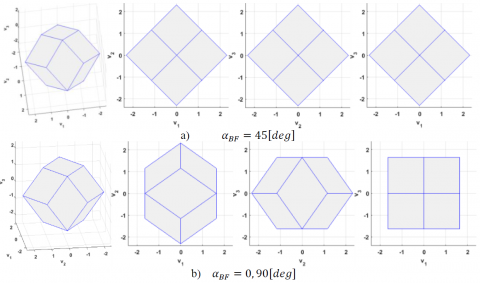
Figure 1. 4-wheel pyramid configuration envelope, 3D-View, Pitch-Yaw, Yaw-Roll, Pitch-Roll
Table 1. 4-wheel pyramid configuration arrangement in BF
|
$\alpha_{D F}=45[\operatorname{deg}],\left(J_{X X}=J_{Z Z}\right)$ $\beta_{D F}=35.2644[d e g]$ |
4-wheel pyramid configuration Wheel Arrangement/ BF |
|
|
$\alpha_{B F}=45[d e g]$ |
$\alpha_{B F}=0,90[\operatorname{deg}]$ |
|
|
$d_{i j} ; d_{12}, d_{13}, d_{14}$ |
1.633, 1.633, 1.633 |
1.633, 1.633, 1.633 |
|
Outer sphere/ Inscribed sphere |
2.3094/1.633=1.414 |
2.3094/1.633=1.414 |
|
Envelope max. distance/UL |
[2.3094,2.3094, 2.3094] |
[1.633,2.3094, 1.633] |
|
Max in X or Z alone/UL Performance increasing factor No. of wheel carry the load |
2.3094 1.414 4 |
1.633 1 2 |
|
Max in equal X and Z together/UL Performance increasing factor |
1.633 1.414 |
1.1547 1 |
|
Both arrangements for the same 4-wheel pyramid configuration have envelope min. distance/UL = 1.633, envelope max. distance/UL (maximum vertices) =2.3094, and minor vertices/UL = 2. UL…unit length |
||
Figure 2. 4-wheel pyramid configuration, $\alpha_{B F}=45[d e g]$, outer and inscribed spheres
In most cases, the configuration angle $\alpha$ is set to $\alpha=45[\operatorname{deg}]$ for symmetry between $X$ and $Z .$ The projections of the wheels spin axes on the $X-Z$ plane are located each $90^{\circ}$. Another configuration angle $\beta$ (cant, skew or elevation angle) is commonly set to $\beta=35.2644[\operatorname{deg}][10] .$ The spin axes of all wheels are equally canted toward the Y-axis by this angle measured from the roll and pitch plane. These values equalize the total $\mathrm{T} / \mathrm{M}$ and maximize the minimum distance from the origin of the envelope to its surface $[8,19] .$ This optimal configuration gives the relative wheels arrangement in the design frame (DF) forming the dodecahedron shape. The dodecahedron contains fourteen vertices, only six are global maxima. The maximum vertices (global maxima) exist at magnitudes equal to $2.309 T_{wmax } / H_{wmax } / H_{wmax } / H_{wmax }[19] .$ The vertices (local maxima) exist at $2 T_{wmax } / H_{wmax }[19] .$ The centers of each facet indicate the minima for each respective plane. These minima are also global minima. The minimum distance from the center of polyhedron to the envelope $d_{i j} T_{\text {wmax}} / H_{\text {wmax}}$ (minimum radius) exists at the middle of the flat facets at magnitudes equal to $1.633 T_{\text {wmax }} /$ whax [ 19]. This dodecahedron shape is generic for any four-wheel system. The shape changes only with changing the number of wheels. The projections of the dodecahedron shape on the SC body frame (BF) are varying with changing the arrangement of the RWs cluster relative to BF. If both frames (DF, and BF ) coincide, the projection of the first wheel spin axis on the X-Z plane is shifted $45[d e g]$ from the X-axis given $\alpha_{B F}=45[d e g]$ arrangement. If DF or the cluster is rotated $45[\operatorname{deg}]$ around Y-axis of BF, the projection of the wheels spin axes on the X-Z plane are located on $0,90,180,$ and $270[\text { deg }]$ from the X-axis, given $\alpha_{B F}=0,90[\text { deg }]$ arrangement. In Figure 1 a, and b show the four-wheel polyhedron for $\alpha_{B F}=45[\operatorname{deg}]$ and $\alpha_{B F}=0,90[\text {deg}]$ arrangements, respectively, in $3 \mathrm{D}$ and three orthogonal views. For $\alpha_{B F}=0,90[\text { deg }]$ arrangement, the control effectiveness matrix defined in Eq. ( 6) is tended to
$\left[A_{w}\right]=\left[\begin{array}{cccc}{0} & {-c \beta} & {0} & {c \beta} \\ {-s \beta} & {s \beta} & {-s \beta} & {s \beta} \\ {c \beta} & {0} & {-c \beta} & {0}\end{array}\right]$ (7)
Table 1 summarizes the performance of 4-wheel pyramid configuration for both arrangements. The minimum distances from the center of polyhedron to the envelope are the same for both arrangements. It is not a function of the arrangement relative to BF, but it is function only in the DF configuration. The $\alpha_{B F}=45[d e g]$ arrangement excel in; envelope maximum distance in X, and Z direction. The maximum permissible torque in X or Z direction alone equals $2.3094 T_{wmax }$ in comparison with $1.633 T_{wmax }$ for the $\alpha_{B F}=0,90[\operatorname{de} g]$ arrangement achieving $41.4 \%$ increase. The same increasing factor is achieved also in case of equal X and Z demand with zero demand in Y direction, where the maximum permissible torque in X and Z directions together equal $1.633 T_{\text {wmax}}$ in comparison with $1.1547 T_{\text {wmax}}$ for the $\alpha_{B F}=0,90[d e g]$ arrangement. Another advantage for the $\alpha_{B F}=45[d e g]$ arrangement appears at $X$ or $Z$ alone demand $d$ nd $d$ de that is the load is carried via four wheels instead of two wheels in case of $\alpha_{B F}=0,90[d e g]$ arrangement. The illustrated cases frequently happen during $\mathrm{SC}$ operation; hence, it is valuable to be taken into consideration during the design process according to the mission.
Figure 2 illustrates that the maximum torque (outer) sphere contains unreachable torque values larger than the envelope capacity. It is larger than the inscribed sphere shown in Figure 2b by a factor of 1.414. Figure 2b illustrates the unused portion from the torque envelope in case of the inscribed sphere. Hence, the factor of 1.414 presented in Table 1 indicates the ability of $\alpha_{B F}=45[d e g]$ arrangement for utilizing the maximum permissible capability of RWs configuration in the direction of dominant maneuvers.
In this section, the choice of using two assemblies, four RWs each, will be discussed. The geometric analysis of this eight RWs cluster is performed and the enhancement of the dynamic capability based on optimal use of this configuration will be discussed. The choice of two assemblies not only increases the capability of the control system when operating together (eight wheels) during imaging mode, but also gives the option of using one assembly only (four wheels) during no imaging modes instead of the total number of wheels. That saves the wheels power consumption at zero speed and torque. Additionally, smaller wheels may be more capable than less large wheels because the envelope would have more flat facets and less physical limitation losses. Thus for different RWs configurations of similar envelopes volumes, the large number RWs configuration allows a larger inscribed sphere as described [19]. To illustrate the previous paragraph, a comparison between two different clusters, eight RWs each, is performed, considering all RWs are in symmetry. Both clusters are consisting of two assemblies (four wheels each). The difference between the two clusters is the relative arrangement of assemblies inside a cluster. In the first cluster, shown in Figure 3a, both assemblies have the same arrangement where the spin axis of the first wheel in the second assembly coincides with the spin axis of the first wheel in the first assembly. Thus, the projections of the spin axes of the wheels on the X-Z plane inside this cluster are allocated twice each $90^{\circ} .$ While in the second cluster, shown in Figure $3 b,$ the projections of the spin axes of the first wheels in each assembly on the $\mathrm{X}-\mathrm{Z}$ plane are shifted $45^{\circ}$ from each other. Thus, the projections of the spin axes of all wheels are set radially symmetrically along the X-Z plane with configuration angle $\alpha_{w}=45^{\circ}$ for symmetry between the roll and pitch axes (uniformly distributed in azimuth about the Y-axis). Another skew configuration angle $\beta_{w}$ (cant angle) is the elevation angle from the $\mathrm{XZ}$ plane. The spin axes of all wheels are equally canted toward the Y-axis by an angle $\beta_{w}$ measured from the roll and pitch plane for both clusters. As the torque requirements about the $\mathrm{X}-$ and $\mathrm{Z}$ -axis increases, the optimum cant angle $\beta_{w}$ decreases.
Figure 3. Eight wheels geometrical configurations
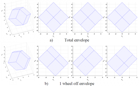
Figure 4. 8-wheel configuration torque envelope, first cluster, 3D, XY, YZ, XZ Views
Figure 5. 8-wheel configuration torque envelope, second cluster, 3D, XY, YZ, XZ Views
Figure 4 shows the torque envelope corresponding to the first cluster. Notice that the same envelope can be obtained from using four RWs with double maximum torque. Figure 5 shows the torque envelope corresponding to the second cluster. Assuming all wheels have equal T/M given by $T_{w \max } / H_{w \max }$ the dimensions of the envelopes are normalized and scaled symmetrically with the size of $T_{w \max } / H_{w \max } / H_{w \max } .$ In Figure $4,$ a) shows the total $\mathrm{T} / \mathrm{M}$ envelope; $\mathrm{b}$ ) shows the envelope in case of one wheel off, $\mathrm{c}$ ) shows the total envelope inscribed sphere, d) shows the inscribed sphere in case of one wheel off. In Figure $5 \mathrm{a}$ shows the total $\mathrm{T} / \mathrm{M}$ envelope, $\mathrm{b}$ ) shows the total envelope inscribed sphere, $\mathrm{c}$ ) shows the inscribed sphere in case of one $\alpha_{B F}=45[d e g]$ wheel off, d) shows the inscribed sphere in case of one $\alpha_{B F}=0,90[\operatorname{deg}]$ wheel off. All figures showed in $3 \mathrm{D},$ pitch-yaw $(\mathrm{XY}),$ yaw-roll $(\mathrm{YZ}),$ and pitch-roll $(\mathrm{XZ})$ views.
Table 2 summarizes several notes from Figure 4 and 5. The first cluster has maximum torque/UL value in X and Z axes of 4.6188 which is greater than 3.9424 of the second cluster. This increased value is due to the characteristic of $\alpha_{B F}=45[\operatorname{deg}]$ arrangement as described in Iable $1 .$ However, the secondcluster has 20.7 % more envelope volume, 10 % more inscribed sphere radius/UL in the case of all-wheel working, and 8.5 % more inscribed sphere radius/UL in case of one wheel off than the first cluster. That is enough to select the second cluster in order to increase the SC agility performance. The outcome envelope volume and inscribed sphere radius are greater than coincident assemblies. Comparing between the inscribed spheres in normal operating case for both clusters shown in Figure 4c, and 5b, it is clear that the inscribed sphere in 1st cluster is tangent to all center points of all facets while in 2nd cluster still there are several facets not reached yet by the inscribed sphere. Wheel failure destroys the symmetry of the shape and significantly reduces the envelope. The reduction in available torque in the direction of minimum capability are 27 %, 28 % of normal values for 1st, and 2nd clusters respectively.
Table 2. 8-wheel pyramid configuration
|
$\alpha_{D F}=45[d e g]$, $\beta_{D F}=35.2644[d e g]$, $\boldsymbol{\tau}_{wi max}=\mathbf{0 . 2}[\boldsymbol{N} \cdot \boldsymbol{m}]$, |
8-wheel pyramid configuration Wheel Arrangement/ BF |
|
|
Assembly 1&2 $\alpha_{B F}=45[\operatorname{deg}]$ |
Assembly $1: \alpha_{B F}=45[\operatorname{deg}]$ Assembly $2: \alpha_{B F}=0,90[\operatorname{deg}]$ |
|
|
Max Torque in each axes/UL |
[4.6188, 4.6188, 4.6188] |
[3.9424,4.6188,3.9424] |
|
Volume[UL3] Envelope volume relative ratio |
197.0689 1 |
237.8832 1.207 |
|
Inscribed sphere radius/UL Inscribed sphere relative ratio |
3.266(2x1.633) 1 |
3.6042 1.1 |
|
In a single wheel failure: volume reduced to 62.5 % |
||
|
Inscribed sphere radius reduction Inscribed sphere radius/UL Inscribed sphere relative ratio |
27% 2.3842 1 |
28% 2.5867 1.085 |
4.1 Control input torque vector for eight RWs configuration
This vector is limited by the available space of the torque envelope of the selected cluster and related to the actual RWs torque vector $\tau_{w}$ by the physical geometrical configuration illustrated in Figure 3 follows:
$[u]=\left[\begin{array}{c}{u_{x}} \\ {u_{y}} \\ {u_{z}}\end{array}\right]=\left[A_{w}\right]\left[\begin{array}{c}{\tau_{w 1}} \\ {\tau_{w 2}} \\ {\tau_{w_{3}}} \\ {\tau_{w 4}} \\ {\tau_{w_{5}}} \\ {\tau_{w_{6}}} \\ {\tau_{w_{8}}}\end{array}\right]=\left[A_{w}\right]\left[\tau_{w}\right]$ (8)
where, $\left[A_{w}\right]$ is the torque distribution matrix defined as
$\left[A_{w}\right]=\left[\begin{array}{cccc}{-c \beta c \alpha} & {-c \beta c \alpha} & {c \beta c \alpha} & {-c \beta c \alpha} & {-c \beta} & {0} & {c \beta} & {0}\\ {-c \alpha} & {c \alpha} & {-c \alpha} & {-c \alpha} & {-c \alpha} & {-c \alpha} & {-c \alpha} & {c \alpha} \\ {c \beta c \alpha} & {-c \beta c \alpha} & {-c \beta c \alpha} & {-c \beta c \alpha} & {0} & {c \beta} & {0} & {c \beta}\end{array}\right]$ (9)
Ignoring the actuator saturation and dynamics which is much faster than the remaining SC dynamics, the relation between the actual RWs torque vector $\tau_{w}$ produced from RWs and the commanded RWs torque vector $\tau_{w c}$ (the amplitude vector of allocated torque of each RW) can be approximated by the steady state relationship $\tau_{w}=\tau_{w c} .$ since the magnitudes of the available T/M may vary in different directions, and $\mathrm{SC}$ is not inertially symmetric in general, the magnitudes of the available body rate and acceleration also vary along the rotational directions. The optimality of agility performance is defined as the ability to achieve largest magnitudes of body rate and acceleration vectors along the worst direction (along which the vectors have minimum magnitude) [15].
4.2 Wheels configuration for optimal agility performance
For the shifted assemblies cluster, the cant angle $\beta_{w}$ can be set to the value which gives the same maximum torque along the SC body axes, $U_{i},(i=x, y, z)$,which are calculated as follows
$\begin{aligned} U_{x}=& \tau_{w \max } \cos \beta_{w}\left(4 \cos \alpha_{w}+2\right) \\ & U_{y}=8 \tau_{w_{-} \max } \sin \beta_{w} \\ U_{z}=& \tau_{wmax}\cos \beta_{w}\left(4 \sin \alpha_{w}+2\right) \end{aligned}$ (10)
for,
$U_{x}=U_{y}=U_{z}$ (11)
where, $\tau_{wmax}$ is the maximum RW torque. The optimalconfiguration angle $\beta_{w}$ can be obtained from equations ( 10) and ( 11) as
$\tan \beta_{w}=\frac{4 \cos \alpha_{w}+2}{8}$ (12)
So, the optimal configuration angle $\beta_{w}$ is set to $\beta_{w}=31.1^{\circ} .$ This choice is made without consideration of the inertia property of the SC.
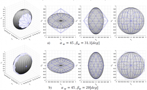
Figure 6. 8-wheel configuration torque envelope
Figure 7. 8-wheel pyramid configuration relative to the corresponding inertia ellipsoid
Another choice of configuration angles can be made with consideration of the SC inertia [15]. It is based on calculating the optimal value of the angle $\beta_{w}$ by equating the body accelerations in 3-axes as follows
$\begin{aligned} a_{x_{-} \max }=\frac{U_{x}}{J_{x x}} &=\frac{\tau_{w_{-} \max } \cos \beta_{w}\left(4 \cos \alpha_{w}+2\right)}{J_{x x}} \\ a_{y_{-} \max } &=\frac{U_{y}}{J_{y y}}=\frac{8 \tau_{w_{-} \max } \sin \beta_{w}}{J_{y y}} \\ a_{z_{-} \max } &=\frac{U_{z}}{J_{z z}}=\frac{\tau_{w_{-} \max } \cos \beta_{w}\left(4 \sin \alpha_{w}+2\right)}{J_{z z}} \end{aligned}$ (13)
for,
$a_{x_{-} \max }=a_{y_{-} \max }=a_{z_{-} \max }$ (14)
where, $J_{x x}=780, J_{y y}=450,$ and $J_{z z}=780\left[K g \cdot m^{2}\right]$ are the SC inertia about principal axes, while the products of inertia are negligible. The optimal configuration angle $\beta_{w}$ can be obtained from equations ( 13) and ( 14) as
$\tan \beta_{w}=\frac{\left(4 \cos \alpha_{w}+2\right) I_{y y}}{8 J_{x x}}$ (15)
So, the optimal configuration angle $\beta_{w}$ is set to $\beta_{w} \approx 20^{\circ} .$ In the practical SC design, the configuration angles choice is a compromise among expected momentum accumulation, required torque, slewing requirements, and convenience of
fabrication. In Figure $6 \mathrm{a}$ shows the 8 -wheel pyramid configuration torque envelope for optimal configuration angles $\alpha_{w}=45, \beta_{w}=31.1[d e g],$ while Figure 66 shows the $\alpha_{w}=45, \beta_{w}=20[\operatorname{deg}]$ configuration. Figure $7 \mathrm{a},$ and $\mathrm{b}$ show the same configurations relative to the corresponding inertia ellipsoid in $3 D,$ Pitch-Yaw, Yaw-Roll, Pitch-Roll views Figure 7 illustrates that the envelope in the $\alpha_{w}=45, \beta_{w}=20[\text { deg}]$ configuration is more consistent to the SC inertia property than the other configuration. This is an indication of the appropriate usage of the available T/M capacity to achieve largest magnitudes of body rate and acceleration according to optimal agility performance definition.
4.3 Calculating maximum capability of RWs system
For the 8 -wheel pyramid configuration cluster of $\alpha_{w}=45, \beta_{w}=20[\operatorname{deg}]$ which is arranged as shown in Figure $3,$ the actual RWs torque vector $\tau_{w}$ consists of $i^{t h}$ RWs delivered torques assuming that.
$\left|\tau_{w i}\right| \leq \tau_{w i_{max} } \quad i=1: 8$ (16)
where, $\tau_{w i_{max }}=0.2[N m]$ is the maximum RW torque. Themaximum RWs torque along the SC body axes $U=\left[U_{x}, U_{x}, U_{x}\right]^{T}$ is calculated according to equations (10) and equal $(0.91 ; 0.55 ; 0.91)[N m]$. The maximum angular moment of individual RW is $H_{w \max }=18[\mathrm{N} . \mathrm{m} . \mathrm{s}] .$ The maximum angular momentum along the SC body axes $\mathrm{H}_{\mathrm{max}}$ is defined similar to equations (10) and equal $(82 ; 50 ; 82)[\mathrm{Nms}]$. The maximum values of the absolute magnitudes of $\mathrm{SC}$ acceleration in 3 -axes are $a_{x_{ max}}=a_{y_{max }}=a_{z_{max}} \approx 0.067\left[\operatorname{deg} / s^{2}\right] .$ The maximum value of the absolute magnitudes of $\mathrm{SC}$ body rates in 3 -axes are $\omega_{x_{-} \max }=\omega_{y_{-} \max }=\omega_{z_{-} \max }=0.0059 H_{w \max } \approx 6[\operatorname{deg} /s]$. It should be noted that the maximum torque, momentum, acceleration or slew rates in 3-axes cannot be obtained simultaneously; instead, each of them is obtained when the total momentum is aligned along the corresponding body axis. Table 3 illustrates the results of the comparison between wheels configuration with and without SC inertia consideration according to the definition of optimality of agility performance. Selecting the wheels’ configuration by equating the body rates or accelerations in 3-axes can achieve, in this case study, 9.85 % increase in SC acceleration vectors along the worst direction as shown by gray color in Figure 8.
Table 3. Wheels configuration with/without consideration of the SC inertia
|
|
same magnitude of total T/M (without consideration of the SC inertia) |
same magnitude of rates/accelerations (with consideration of the SC inertia) |
|
Angles $\alpha_{w}, \beta_{w}[\operatorname{deg}]$ |
45°,31.1° |
45°,20° |
|
Max absolute momentum [N. m . s] |
(74.4;74.4;74.4) |
(82;48;82) |
|
Max abs. body rate [deg/s] |
(5.5;9.4;5.5) |
(6;6;6) |
|
Planning body rate [deg/s] |
5.5 |
6 |
|
Max absolute torque [N. m] |
(0.83;0.83;0.83) |
(0.91;0.55;0.91) |
|
Max abs. acceleration $\left[\operatorname{deg} / s^{2}\right]$ |
(0.061;0.104;0.061) |
(0.067;0.067;0.067) |
|
Planning acceleration $\left[\operatorname{deg} / s^{2}\right]$ |
0.061 |
0.067 |
|
Agility increasing ratio |
---- |
9.85% |
Figure 8. Achieved acceleration according to maximum agility definition
4.4 Updating of system capability
Maximum system capability should be updated onboard according to RWs in use. Table 4 shows the maximum capability of RWs system in case of octahedron pyramid configuration cluster of shifted assemblies with consideration of the SC inertia $\alpha_{w}=45, \beta_{w}=20[\operatorname{deg}] .$ The eight wheels are assumed identical, maximum RW torque is $\tau_{w i \max }=0.2[N . m],$ inclined to the pitch-roll plane by same angle $\beta_{w}=20[d e g]$ and equally spaced around yaw axis by an angle $\alpha_{w}=45[\operatorname{deg}] .$ For this designed case with eight RW in use, the maximum values of the absolute magnitudes of SC acceleration and body rates are equal in 3 -axes and equal $0.067\left[\operatorname{deg} / s^{2}\right]$ and $6.1[\operatorname{deg} / s]$, respectively. By getting one wheel off or more, the equality of maximum values of $\mathrm{SC}$ acceleration in 3 -axes cannot be maintained. For one $\mathrm{RW}$ off from the first complex, equal reductions in maximum values of SC acceleration in pitch and roll directions are obtained as expected from angle $\alpha_{w}=45[\operatorname{deg}]$ and the maximum values of the absolute magnitudes of $\mathrm{SC}$ acceleration are reduced to $(0.057 ; 0.060 ; 0.057)\left[\operatorname{deg} / s^{2}\right] .$ For one $\mathrm{RW}$ off from the second complex, the reduction in maximum values of $\mathrm{SC}$ acceleration is in pitch or roll direction according to fault $\mathrm{RW}$ configuration. The maximum values of the absolute magnitudes of SC acceleration are reduced to $(0.053 ; 0.060 ;0.067)\left[\operatorname{deg} / s^{2}\right]$ in case of $\mathrm{RW} 5$ or RW7 fault and $(0.067 ;0.060 ; 0.053)\left[\operatorname{deg} / s^{2}\right]$ in case of RW6 or RW8 fault.
The used way to submit the attitude controller by the maximum values of the absolute magnitudes of SC acceleration in 3-axes is using predefined matrix. The elements of this predefined matrix are the worst case values corresponding to the number of wheels in use. For one RW off, the worst-case values are (0.053; 0.060; 0.053) $\left[\operatorname{deg} / s^{2}\right]$. The attitude controller is submitted with the allowable values of SC acceleration in 3-axes. These values can be calculated exactly depending not only on the number of wheels in use, but also on its configurations. When a fault occurs and one or more RWs are turned off, the corresponding columns in torque distribution matrix are nulled and the allowable acceleration is calculated according to the updated torque distribution matrix.
Table 4. Maximum capability of RWs system according to number of RWs in use
|
RW on |
RW off |
Max torque $[N, m]$ |
Max acceleration $\left[\operatorname{deg} / s^{2}\right]$ |
Max momentum $[N, m, s]$ |
Max body rate $[\operatorname{de} g / s]$ |
|
8 |
- |
(0.91;0.55;0.91) |
(0.067;0.067;0.067) |
(82;49;82) |
(6.1;6.1;6.1) |
|
7 |
1or2or3or4 |
(0.77;0.48;0.77) |
(0.057;0.060;0.057) |
(69.7;43.1;69.7) |
(5.1;5.4;5.1) |
|
5or7 |
(0.72;0.48;0.91) |
(0.053;0.060;0.067) |
(64.8;43.1;81.7) |
(4.8;5.4;6) |
|
|
6or8 |
(0.91;0.48;0.72) |
(0.067;0.060;0.053) |
(81.7;43.1;64.8) |
(6;5.4;4.8) |
|
|
worst case value for one wheel off |
(0.72;0.48;0.72) |
(0.053;0.060;0.053) |
(64.8;43.1;64.8) |
(4.8;5.4;4.8) |
|
|
6 |
1,2or3,4or1,3or2,4or1,4or2,3 |
(0.64;0.41;0.64) |
(0.047;0.052;0.047) |
(57.7;36.9;57.7) |
(4.3;4.7;4.3) |
|
5,6or7,8or5,8or6,7 |
(0.72;0.41;0.72) |
(0.053;0.052;0.053) |
(64.8;36.9;64.8) |
(4.8;4.7;4.8) |
|
|
5,7 |
(0.53;0.41;0.91) |
(0.039;0.052;0.067) |
(47.8;36.9;81.7) |
(3.5;4.7;6) |
|
|
6,8 |
(0.91;0.41;0.53) |
(0.067;0.052;0.039) |
(81.7;36.9;47.8) |
(6;4.7;3.5) |
|
|
1,5or1,7 |
(0.59;0.41;0.77) |
(0.043;0.052;0.057) |
(52.8;36.9;69.7) |
(3.9;4.7;5.1) |
|
|
1,6or1,8 |
(0.77;0.41;0.59) |
(0.057;0.052;0.043) |
(69.7;36.9;52.8) |
(5.1;4.7;3.9) |
|
|
worst case value for two wheels off |
(0.53;0.41;0.53) |
(0.039;0.052;0.039) |
(47.8;36.9;47.8) |
(3.5;4.7;3.5) |
For the case of one RW fault, as illustrated in Table 4, the maximum values of the absolute magnitudes of SC acceleration are reduced to one of the following values (0.057; 0.060; 0.057), (0.053;0.060;0.067) or (0.067;0.060;0.053) according to fault RW instead of reduced to the worst case values (0.053;0.060;0.053) corresponding to the number of wheels in use. Using this dynamic way to calculate the maximum values of the absolute magnitudes of SC acceleration in 3-axes, up to 26.23 % increase in SC acceleration in the roll or pitch channels can be obtained in this case study for one RW off whereas up to 71.7 % increase in SC acceleration in roll or pitch channels for two RW off in comparison of the traditional way. An algorism can be used to implement this dynamic way for calculating the maximum values of the absolute magnitudes of SC acceleration in 3-axes in order to increase the used acceleration.
4.5 Forced drop of system capability
Traditionally, maximum capability of RWs system is calculated or selected based on the worst case values as shown in Table 4. The maximum capability according to the number of RWs in use for the cases of 5, 4, and 3 RWs was calculated. Results are summarized in Table 5, that shows the forced capability reduction in case of three RW fault (5 working RW) to the capability of just 4 RW working. In the RW octahedron cluster pyramid configuration, the forced drop lagged till third RW fault. While in other configurations, this drop may appear from the first RW fault.
Table 5. Brief results of maximum capability for 5,4, and 3 RWs
|
RW on |
RW off |
Max torque $[N, m]$ |
Max acceleration $\left[d e g / s^{2}\right]$ |
Max momentum $[N, m, s]$ |
Max body rate $[\operatorname{deg} / s]$ |
|
5 |
three |
(0.4;0.274;0.4) |
(0.030;0.035;0.030) |
(33.8;24.6;33.8) |
(2.5;3.1;2.5) |
|
4 |
four |
(0.4;0.274;0.4) |
(0.030;0.035;0.030) |
(33.8;24.6;33.8) |
(2.5;3.1;2.5) |
|
3 |
five |
(0.188;0.137;0.188) |
(0.014;0.017;0.014) |
(16.9;12.3;16.9) |
(1.2;1.5;1.2) |
4.6 Combined enhancement of system capability
The dynamic capability can be enhanced due to the combination of the capability enhancement based on selecting wheels configuration with consideration of the SC inertia $\left(\alpha_{w}=45[\operatorname{deg}], \beta_{w}=20[\operatorname{deg}]\right)$ and capability update based on torque distribution matrix update with RW fault. The obtained enhancement can be analyzed as follows;
For no RW fault, the capability enhancement is only based on selecting wheels configuration with consideration of the SC inertia $\left(\alpha_{w}=45[\operatorname{deg}], \beta_{w}=20[\operatorname{deg}]\right)$. The enhancement in this case study equals 9.85 %.
For one RW fault, the combined capability enhancement is illustrated in Table 6. The enhancement in this case study can reach to 38.51 % in pitch or roll channels.
Table 6. Combined capability enhancement
|
Max abs. acceleration $\left[\mathrm{deg} / \mathrm{s}^{2}\right]$ in Pitch or Roll channels for one RW fault |
Capability enhancement based on selecting wheels configuration with consideration of the SC inertia |
||
|
Not applied |
Applied |
||
|
Capability updated based on torque distribution matrix updating |
Not applied |
0.0483 |
0.0530(9.8%) |
|
Applied |
0.0609(26.38%) |
0.0669(38.5%) |
|
The SC agility performance is achieved by maximizing the dynamic capability of the RWs system based on the optimal use of RWs configurations and arrangements relative to SC BF. The octahedron pyramid configuration cluster of shifted assemblies, $\alpha_{B F}=45$ and $0,90[\operatorname{deg}]$, has 20.7 % more envelope volume, 10 % more inscribed sphere radius/UL in case of all wheels working, and 8.5 % more inscribed sphere radius/UL in the case of one wheel off than the coincident assemblies. The cluster of shifted assemblies ensures either the same magnitude of total T/M along the SC body axes when $\beta_{w}=31.1[\operatorname{deg}],$ or equating the body accelerations in 3 -axes when $\beta=20[\operatorname{deg}] .$ The last configuration maximizes the system capability according to the optimal agility performance definition satisfying 9.85 % increase in SC acceleration vectors along the worst direction. The limiting values of the SC acceleration in 3-axes are submitted to the attitude controller exactly depending not only on the number of wheels in use, but also on its configuration and arrangement relative to SC BF. This task is accomplished dynamically via updating of the torque distribution matrix. Increasing of SC acceleration in roll or pitch channels up to 26.23 % can be obtained in this case study for one RW off in comparison to the traditional way. The combined capability enhancement increases the SC agility and productivity from 9.85 % without RW fault to 38.51 % with one RW fault in comparison to the traditional way. This has a direct influence on RW selecting, sizing, and time of maneuvers executing.
[1] Kim, D., Turner, J.D. (2014). Near-minimum-time control of asymmetric rigid spacecraft using two controls. Automatica, 50(8): 2084-2089. https://doi.org/10.1016/j.automatica.2014.05.038
[2] Ousaloo, H.S. (2018). Attitude acquisition from an arbitrary tumbling state using two skewed reaction wheels. Aerospace Science and Technology, 72: 84-94. https://doi.org/10.1016/j.ast.2017.10.040
[3] Cao, X., Yue, C., Liu, M., Wu, B. (2016). Time efficient spacecraft maneuver using constrained torque distribution. Acta Astronautica, 123: 320-329. https://doi.org/10.1016/j.actaastro.2016.03.026
[4] Kang, X., Xiao, C., Yanning, G., Guangfu, M. (2015). Moment error minimized direct control allocation for redundant reaction wheel configurations. In 2015 34th Chinese Control Conference (CCC), IEEE, pp. 871-876. https://doi.org/10.1109/ChiCC.2015.7259749
[5] Ran, D., Chen, X., de Ruiter, A., Xiao, B. (2018). Adaptive extended-state observer-based fault tolerant attitude control for spacecraft with reaction wheels. Acta Astronautica, 145: 501-514. https://doi.org/10.1016/j.actaastro.2018.01.021
[6] Bayard, D.S. (2001). An optimization result with application to optimal spacecraft reaction wheel orientation design. In Proceedings of the 2001 American Control Conference. (Cat. No.01CH37148) Arlington, VA, USA. https://doi.org/10.1109/ACC.2001.945932
[7] Ismail, Z., Varatharajoo, R. (2010). A study of reaction wheel configurations for a 3-axis satellite attitude control. Advances in Space Research, 45(6): 750-759. https://doi.org/10.1016/j.asr.2009.11.004
[8] Hablani, H.B. (1994). Sun-tracking commands and reaction wheel sizing with configuration optimization. Journal of Guidance, Control, and Dynamics, 17(4): 805-814. https://doi.org/10.2514/3.21270
[9] Yoon, H., Seo, H.H., Park, Y.W., Choi, H.T. (2015). A new minimum infinity-norm solution: With application to capacity analysis of spacecraft reaction wheels. In 2015 American Control Conference (ACC), IEEE, pp. 1241-1245. https://doi.org/10.1109/ACC.2015.7170903
[10] Markley, F.L., Crassidis, J.L. (2014). Fundamentals of spacecraft attitude determination and control (Vol. 33). New York: Springer.
[11] Boulouma, S., Labiod, S., Boubertakh, H. (2018). Direct adaptive control of a flexible spacecraft with disturbances and uncertain actuator failures. Mechanical Systems and Signal Processing, 110: 73-89. https://doi.org/10.1016/j.ymssp.2018.03.007
[12] Koh, D., AlSayegh, A., Lee, H. (2016). In-orbit performance of attitude control system in DubaiSat-2. In 14th International Conference on Space Operations, pp. 1-12. https://doi.org/10.2514/6.2016-2600
[13] Tang, S.Y., Cao, X.B., Zhang, Y.L. (2012). Configuration optimization of four dissimilar redundant flywheels with application to IPACS. In Proceedings of the 31st Chinese Control Conference, IEEE, pp. 4664-4669.
[14] Tang, S.Y., Wu, J.J., Liu, K., Zhang, Y.L. (2012). Optimal configuration design of redundant flywheels and hardware-in-the-loop simulation. In Proceedings of the 31st Chinese Control Conference, IEEE, pp. 4334-4338.
[15] Yoon, H., Seo, H.H., Choi, H.T. (2014). Optimal uses of reaction wheels in the pyramid configuration using a new minimum infinity-norm solution. Aerospace Science and Technology, 39: 109-119. https://doi.org/10.1016/j.ast.2014.09.002
[16] King, J.T., Karpenko, M. (2016). A simple approach for predicting time-optimal slew capability. Acta Astronautica, 120: 159-170. https://doi.org/10.1016/j.actaastro.2015.12.009
[17] Karpenko, M., King, J.T. (2018). Maximizing agility envelopes for reaction wheel spacecraft. Proceedings of the Institution of Mechanical Engineers, Part G: Journal of Aerospace Engineering. https://doi.org/10.1177/0954410018787866
[18] Crews, I.I., Steven, R. (2013). Increasing slew performance of reaction wheel attitude control systems. Naval Postgraduate School Monterey CA.
[19] Markley, F.L., Reynolds, R.G., Liu, F.X., Lebsock, K.L. (2010). Maximum torque and momentum envelopes for reaction wheel arrays. Journal of Guidance, Control, and Dynamics, 33(5): 1606-1614. https://doi.org/10.2514/1.47235