Hongyan Chu* | Liting Xu | Yuexin Liu
OPEN ACCESS
This paper puts forward an optimal power allocation algorithm based on maximum rate and interference constraint, aiming to solve the shortage of spectrum resources and enhance spectrum utilization efficiency and channel data rate in cognitive radio (CR) networks. Specifically, the maximization of successful bit transfer rate was converted into a convex optimization problem using the cognitive relay system model, and then the optimal power allocation plan was derived under the Karush–Kuhn–Tucker (KKT) conditions. The proposed algorithm was compared with another two algorithms through simulation experimental simulation. The results show that our algorithm outperformed the contrastive algorithms in channel utilization rate. The proposed algorithm can reduce the outage probability, increase the overall data rate and enhance channel utilization of CR networks.
cognitive radio (CR) network, interference level constraint, power allocation, rate optimization, Karush-Kuhn–Tucker (KKT) conditions
The rapid development of wireless communication networks has stimulated the demand for high-data rate services. However, the radio frequency bands required by most wireless communication systems are scarce spectrum resources. The shortage of spectrum resources can be solved by the cognitive radio (CR) technology. The CR, known for its learning ability and information exchange with the surrounding environment, has been adopted to sense and utilize the available spectrum in the space, thereby reducing the spectrum conflicts and improve spectrum utilization efficiency [1-3]. In CR systems, the licensed spectrum can be used by informal users, a.k.a. secondary users (SUs), provided that the primary users (PUs) have received quality services. In other words, a CR system will provide the SUs with spectrum access in a flexible and intelligent manner, without affecting the use of the SUs [4, 5]. There are now two types of spectrum access methods, namely, the opportunistic access and spectrum sharing. The former method allows the SUs to send data in a spectrum segment only if the segment is not occupied by PUs data transmission. By contrast, the spectrum sharing approach allows the SUs and the PUs to transmit data in the same time period, but the interference level of the SUs to the PUs must be kept below a certain threshold, eliminating the interreference in the PUs communication [6].
Many new algorithms have emerged for the power allocation of CR systems. For example, Liu et al. [7] designed a multi-channel CR spectrum-aware algorithm for the SUs and power allocation, which aims to maximize the total throughput of all sub-channels of the SUs based on the existence condition of the PUs; specifically, the sub-channel SUs and transmission power are jointly allocated through alternate direction optimization, thereby enhancing the SUs throughput. Luo et al. [8] developed a CR network power allocation algorithm based on optimal relay selection; the algorithm, using orthogonal frequency division multiplexing modulation (OFDM), derives the joint power optimization and allocation strategy for cognitive source node and optimal relay nodes, which maximizes the information transmission rate of cognitive users, suppresses system interference, and improves system performance. Lu et al. [9] proposed a CR two-way relay plan adapted to low signal-to- interference + noise ratio (SINR) as well as its optimal power and time slot allocation; targeting the shortage of spectrum resources, this fairness-based plan offers a two-way relay algorithm for optimal power allocation that can realize the achievable end-to-end rate of two-way communication. Li et al. [10] put forward a CR network power allocation algorithm based on sequential search and beamforming; the algorithm can effectively improve network performance in two steps: solving the corresponding non-convex optimization problems through uniform quantization and sequential search, and conducting multi-variable search under single-input multi-output and multi-input single-output cognitive links. Mahdi et al. [11] created a power allocation algorithm for CR networks based on nonlinear analysis of power amplifier; considering the signal-to-noise ratio (SNR) of the received signal and channel interference, the algorithm adjusts the parameters of the power amplifier within a limited dynamic range, and deduces the probabilistic analytical expression of data transmission, thus improving the power consumption of the system. Based on the hybrid automatic repeat request (HARQ) main system, Song et al. [12] came up with a power allocation algorithm adaptive to the CR network rate, in which the main system analyzes the mean throughput of the primary and secondary systems by the HARQ and prepares the optimization equation to maximize the mean network throughput.
In light of the above, this paper attempts to design a method for the SUs to effectively utilize spectrum resources with minimal interferences to the PUs through adjustment of the system power, when the spectrum sharing is adopted as the spectrum access method.
Our research tackles a CR system containing a base station, a PU, a pair of SUs, and n relay nodes. The system obeys the following assumptions: the two SUs have no directly connection, but exchange information between two time slots via the cognitive relay nodes [13, 14]; all nodes are synchronized and work in half-duplex with a single antenna; the SUs and PU share the spectrum at the transmitter and the instantaneous channel state information is available; the data transmission is subjected to additive noise and the path loss exponent λ(λ>0) is affected by flat Rayleigh fading.
The cognitive relay system model mainly focuses on the communication between the two SUs, denoted as SU1 and SU2, under the amplify-and-forward (AF) relay protocol with the aid of relay Re [15-17]. In the first time slot, the SU1 and SU2 respectively transmit the unit power signals S1 and S2 to the relay Re. Then, the power signal received by the Re can be expressed as:
$\begin{aligned} H_{\mathrm{Re}} &=3 \log _{2}\left(g_{1} S_{1} \sqrt{p_{1}}+g_{2} S_{2} \sqrt{p_{2}}\right) \\ &+\psi_{R}+\gamma_{R} \end{aligned}$ (1)
where g1 and g2 are the channel gains from the two SUs to the relay, respectively; p1 and p2 are the transmitting powers of SU1 and SU2, respectively; ψR is the additive white Gaussian noise in the relay Re; γR is the interference from the PU. In the second time slot, the relay Re broadcasts the amplified signal. The amplification gain can be expressed as:
$F=p_{\mathrm{Re}} \frac{\sqrt{\left(p_{1}+p_{2}\right)}}{\left(p_{1} g_{1}+p_{2} g_{2}\right)^{2}+\psi_{R}^{m}+\gamma_{R}^{m}}$ (2)
where $\psi_{R}^{m}$ is the maximum additive white Gaussian noise in the relay Re; $\gamma_{R}^{m}$ is the maximum interference from the PU to the relay Re; pRe is the transmitting power of the relay Re. Assuming that the signal is sent from the relay to the SU and the reverse channel gain is the reciprocal of the channel gain, the signals received by SU1 and SU2 via the relay Re can be respectively described as:
$\begin{aligned} H_{1}=& 3 \log _{2}\left(g_{1} S_{1} \sqrt{p_{1}}+g_{2} S_{2} \sqrt{p_{2}}\right) F \\ &+g_{1}\left(\psi_{R}+\gamma_{R}\right) F+\psi_{1}+\gamma_{1} \end{aligned}$ (3)
$\begin{aligned} H_{2}=& 3 \log _{2}\left(g_{1} S_{1} \sqrt{p_{1}}+g_{2} S_{2} \sqrt{p_{2}}\right) F \\ &+g_{2}\left(\psi_{R}+\gamma_{R}\right) F+\psi_{2}+\gamma_{2} \end{aligned}$ (4)
where ψ1 and ψ2 are the additive white Gaussian noises in SU1 and SU2, respectively; γ1 and γ2 are the interference from the PU to SU1 and SU2, respectively. Assuming that each user knows about the relay amplification factor and has its own transmission symbol, and that the self-interference can be removed from the received signal, the SINRs of SU1 and SU2 can be respectively depicted as:
$S I N R_{1}=\frac{p_{\mathrm{Re}} p_{2}\left(g_{1} g_{2}\right)^{2}}{p_{\mathrm{Re}} W_{\mathrm{Re}}+W_{1} \log _{2}\left(p_{1} g_{1}^{2}+p_{2} g_{2}^{2}\right)}$ (5)
$S I N R_{2}=\frac{p_{\mathrm{Re}} p_{1}\left(g_{1} g_{2}\right)^{2}}{p_{\mathrm{Re}} W_{\mathrm{Re}}+W_{2} \log _{2}\left(p_{1} g_{1}^{2}+p_{2} g_{2}^{2}\right)}$ (6)
where WRe, W1 and W2 are
$W_{\mathrm{Re}}=\ln \psi_{R}^{m}+\ln \gamma_{R}^{m}$ (7)
$W_{1}=\ln \psi_{1}^{m}+\ln \gamma_{1}^{m}$ (8)
$W_{2}=\ln \psi_{2}^{m}+\ln \gamma_{2}^{m}$ (9)
Let vs be the maximum total successful bit transfer rate in SUs communication and PT is the maximum interference level allowed by the PU. An excessively high total power of SUs communication may cause great interference to the PU, and waste lots of resources. Hence, it is assumed that pRe is the total transmitting power available for secondary users SUs and the relay Re. Then, the maximum total successful bit transfer rate vs can be expressed as:
$v_{s}=\left(1-P_{1, u}\right) v_{1}+\left(1-P_{2, u}\right) v_{2}$ (10)
where v1 and v2 are the instantaneous rates of SU1 and SU2, respectively; Pi,uis the probability that the defined instantaneous rate v1 is below the required data rate vT,1:
$P_{\mathrm{i}, u}=\operatorname{Pr}\left\{v_{1} \leq v_{T, 1}\right\}$ (11)
Thus, the outage probabilities of SU1 and SU2 can be respectively calculated as:
$P_{1, u}=\left(\frac{p_{\mathrm{Re}} / W_{1}+p_{1} / W_{\mathrm{Re}}+d_{r, 1}^{2}}{\left(p_{\mathrm{Re}} / W_{1}\right)\left(p_{2} / W_{\mathrm{Re}}\right)}\right)\left(\frac{\zeta_{1}}{p_{1} / W_{\mathrm{Re}}}\right)$ (12)
$P_{1, u}=\left(\frac{p_{\mathrm{Re}} / W_{1}+p_{1} / W_{\mathrm{Re}}+d_{r, 1}^{2}}{\left(p_{\mathrm{Re}} / W_{1}\right)\left(p_{2} / W_{\mathrm{Re}}\right)}\right)\left(\frac{\zeta_{1}}{p_{1} / W_{\mathrm{Re}}}\right)$ (13)
where dr,1 and dr,2 are the distance between the relay and SU1 and SU2, respectively; ζ1 and ζ2 can be respectively expressed as:
$\zeta_{1}=2 \exp \left(\left|v_{1}-v_{T, 1}\right|\right)$ (14)
$\zeta_{1}=2 \exp \left(\left|v_{2}-v_{T, 2}\right|\right)$ (15)
However, it is difficult to calculate the exact vs because the instantaneous rate vi varies with the elapse of time. As a result, the instantaneous rate is replaced here by the required data rate vt,1 to approximate the total successful bit transfer rate. The result will be smaller than the effective value. In this way, the maximization of successful bit transfer rate can be converted into:
$\max v_{s}=\max \left(1-P_{1, u}\right) v_{T, 1}+\left(1-P_{2, u}\right) v_{T, 2}$
$s t\left\{\begin{array}{c}{p_{\mathrm{Re}}, p_{1}, p_{2}>0} \\ {p_{\mathrm{Re}}+p_{1}+p_{2} \leq p_{T}}\end{array}\right.$ (16)
Therefore, the objective function is also a convex optimization problem, for the function is a linear combination between P1,u and P2,u and all constraints are linear. Such a problem can be solved under the Karush–Kuhn–Tucker (KKT) conditions, making it possible to obtain different effective solutions. The KKT conditions are generally solved by expressing the objective function in Lagrangian form and deriving the necessary conditions for the optimal value. In the CR network, different optimal solutions should be adopted according to the possible cases under the conditions of actual user environment. Here, all possible cases of the CR network are taken into account and the optimal solution in each case is obtained. The specific steps are as follows:
Case 1: The interference is below the power level threshold. The total available power is limited when the interferences from SU1, SU2 and the relay to the PU are below the power level threshold set by the PU. In this case, the performance of all nodes should be optimized through thorough utilization of the total power. Considering the relatively high complexity, the solution was simplified as follows under the assumption that the two SUs are subjected to roughly the same noise and interference:
${{p}_{1}}={{p}_{\max ,1}}=\frac{{{P}_{T}}({{W}_{\operatorname{Re}}}(\sqrt{{{d}_{r,1}}/{{v}_{T,1}}}\sqrt{{{d}_{r,2}}/{{v}_{T,2}}})+{{\zeta }_{2}}{{v}_{T,2}})}{{{\log }_{2}}({{W}_{\operatorname{Re}}}-{{W}_{1}})\sqrt{{{d}_{r,2}}{{\zeta }_{2}}{{v}_{T,2}}}}+\frac{{{P}_{T}}({{W}_{1}}(\sqrt{{{d}_{r,1}}/{{v}_{T,1}}}\sqrt{{{d}_{r,2}}/{{v}_{T,2}}})+{{\zeta }_{1}}{{v}_{T,2}})}{{{\log }_{2}}({{W}_{\operatorname{Re}}}-{{W}_{1}}){{\zeta }_{1}}{{\zeta }_{2}}({{W}_{\operatorname{Re}}}-{{W}_{2}})}$ (17)
${{p}_{2}}={{p}_{\max ,2}}=\frac{{{P}_{T}}({{W}_{\operatorname{Re}}}(\sqrt{{{d}_{r,1}}/{{v}_{T,1}}}\sqrt{{{d}_{r,2}}/{{v}_{T,2}}})+{{\zeta }_{1}}{{v}_{T,1}})}{{{\log }_{2}}({{W}_{\operatorname{Re}}}-{{W}_{2}})\sqrt{{{d}_{r,2}}{{\zeta }_{2}}{{v}_{T,1}}}}+\frac{{{P}_{T}}({{W}_{2}}(\sqrt{{{d}_{r,1}}/{{v}_{T,1}}}\sqrt{{{d}_{r,2}}/{{v}_{T,2}}})+{{\zeta }_{2}}{{v}_{T,1}})}{{{\log }_{2}}({{W}_{\operatorname{Re}}}-{{W}_{2}}){{\zeta }_{1}}{{\zeta }_{2}}({{W}_{\operatorname{Re}}}-{{W}_{1}})}$ (18)
$p_{\mathrm{Re}}=p_{\max , \mathrm{Re}}=p_{T}-p_{\max , 1}-p_{\max , 2}$ (19)
In this way, the maximum transmitting powers of SU1 and SU2 can be obtained without exceeding the interference level threshold set by the PU.
Case 2: The interference starts to exceed the power level threshold, suppressing the transmitting power of the relay. Since the relay is the closest to the PU, the power allocation optimization can be described as:
$p_{1}=p_{\max , 1}=\frac{2 \pi \zeta_{2}\left(d_{r, 1} W_{\mathrm{Re}}\right) p_{\mathrm{max}, \mathrm{Re}}}{\zeta_{1} W_{1} W_{2}\left(\left|d_{r, 2}-d_{r, 1}\right|\right)}$ (20)
$p_{2}=p_{\max , 2}=\frac{2 \pi \zeta_{1}\left(d_{r, 2} W_{\mathrm{Re}}\right) p_{\max , \mathrm{Re}}}{\zeta_{2} W_{1} W_{2}\left(\left|d_{r, 1}-d_{r, 2}\right|\right)}$ (21)
$p_{\mathrm{Re}}=p_{\mathrm{max}, \mathrm{Re}}=\frac{p_{T}}{g_{\mathrm{Re}}}$ (22)
Case 3: The interference starts to exceed the power level threshold, suppressing the transmitting powers of the SUs. It can be found that the objective function will be a monotonically increasing function of the relay power. To optimize the successful bit transfer rate, the relay should be assigned the maximum possible power. Nevertheless, the assignment may cause the relay power to exceed the interference level threshold of the PU. Therefore, the maximum transmitting power of the relay should be determined according to the minimum transmitting powers pmin,1 and pmin,2 of SU1 and SU2:
$p_{\mathrm{Re}}=p_{\mathrm{max}, \mathrm{Re}}=p_{T}-p_{\min 1}-p_{\min 2}$ (23)
Case 4: The interference starts to exceed the power level threshold, suppressing the transmitting powers of the SUs and the relay. In this case, the total successful bit transfer rate converges to a certain level, making it meaningless to increase the total power. Therefore, the optimal power allocation plan can be described as:
$p_{1}=p_{\max , 1}=\frac{p_{T}-g_{2}^{2} p_{\max , 2}}{g_{1}^{2}}$ (24)
$p_{2}=p_{\max , 2}=p_{T}\left(\frac{\zeta_{1}}{\zeta_{2}} \sqrt{d_{r, 1} d_{r, 2}} p_{\max , \mathrm{Re}} W_{1} W_{2}\right)$$-\sqrt{d_{r, 1} W_{1} \zeta_{1}} p_{\max . R_{e}}$$-\sqrt{d_{r, 2} W_{2} \zeta_{2}} p_{\max , \operatorname{Re}}$ (25)
$| p_{\mathrm{Re}}=p_{\max , \mathrm{Re}}=\frac{p_{T}}{g_{\mathrm{Re}}}$ (26)
This section verifies the performance of the proposed optimal power allocation algorithm under the interference level threshold set by the PU, and compares the algorithm with Li’s algorithm and Majidi’s algorithm [10, 11]. The three algorithms were simulated with the same parameters.
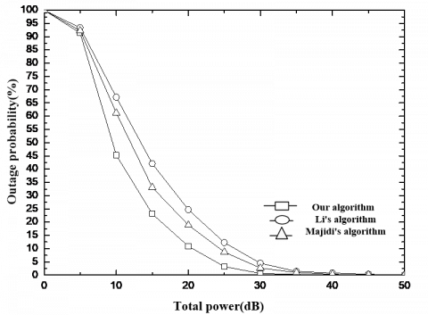
The total power was changed in (0dB, 50dB) and the relay was located between the two SUs. The path loss factor was α=4, and the other simulation parameters were set as: W1=0.4, W2=0.6, WRe=0.7, g1=0.34, g2=0.40, gRe=0.50, pT=12, vT,1=2.0 and vT,1=2.5. Under the said interference level threshold, the outage probabilities, total successful bit transfer rates and channel utilization rates of the three algorithms at different total powers are displayed in Figures 1, 2 and 3, respectively.
Figure 1. Outage probabilities at different total powers
As shown in Figure 1, the outage probabilities gradually decreased with the growth in total power. At a low total power, the communication was poor as the SUs were not efficiently accessed to the channel, which pushes up the outage probabilities. After the total power increased to 30 dB, the decline of outage probabilities of the three algorithms became gentle and approached zero, despite any further growth of the total power. Among them, the proposed algorithm was faster than the other two algorithms in the reduction of outage probability when the total power rose from 5 dB to 30 dB. This means our algorithm can reduce the outage probability faster than other algorithms with the gradual increase of the total power.
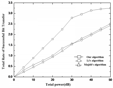
Figure 2. Total successful bit transfer rates at different total powers
As shown in Figure 2, the total successful bit transfer rates exhibited a gradual growth with the increase of the total power. Our algorithm enjoyed the largest growth amplitude. When the total power reached 30 dB, the growth rate of our algorithm started to slow down but stayed above 2.5 kbps/s, and eventually reached 3.5 kps/s, while the contrastive algorithms failed to surpass 2.5 kbps/s. The comparison shows that the total successful bit transfer rate, as well as the data transfer rate, of the proposed algorithm is faster than that of the other two algorithms.
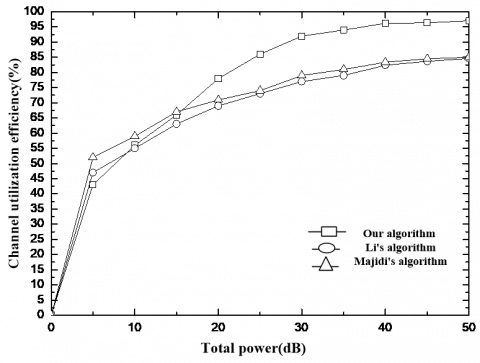
Figure 3. Channel utilization rates at different total powers
As shown in Figure 3, the proposed algorithm utilized the channel less efficiency than the other two algorithms when the total power was below 15 dB. However, the channel utilization rate of our algorithm increased much more significantly than that of the contrastive algorithms after the total power surpassed 15 dB. This means our algorithm is more prone to the effect of total power variation than the other algorithms. However, our algorithm is still more efficient in channel utilization than these algorithms, because it could achieve a greater-than-95 % channel utilization rate, compared to less-than-85 % of the latter.
This paper proposes an optimal power allocation algorithm for CR networks based on maximum rate and interference level constraint. Firstly, a single-antenna half-duplex cognitive relay system was established to analyze the maximum interference level allowed by the PU. Then, the objective function for the maximum total successful bit transfer rate was put forward through exploring the outage probabilities and transmitting powers of the two SUs. After that, the power allocation to the relay nodes was optimized under the KKT conditions, coupled with the linear constraint formulas on the interference level and relay power. Finally, the proposed algorithm was compared with two other algorithms through experimental simulation. The results show that our algorithm outperformed the contrastive algorithms in reducing outage probability, improving total data rate and enhancing channel utilization rate.
[1] Li, L., Zhou, X., Xu, H., Li, G., Wang, D., Soong, A. (2011). Simplified relay selection and power allocation in cooperative cognitive radio systems. IEEE Transactions on Wireless Communications, 10(1): 33-36. http://dx.doi.org/10.1109/TWC.2010.101810.100311
[2] Xie, R., Yu, F.R., Ji, H. (2012). Energy-efficient spectrum sharing and power allocation in cognitive radio femtocell networks. 2012 IEEE Conference on Computer Communications, INFOCOM, 1665-1673. http://dx.doi.org/10.1109/INFCOM.2012.6195537
[3] Karaca, M., Khalil, K., Ekici, E., Ercetin, O. (2013). Optimal scheduling and power allocation in cooperate-to-join cognitive radio networks. IEEE/ACM Transactions on Networking, 21(6): 1708-1721. http://dx.doi.org/10.1109/TNET.2012.2230187
[4] Son, K., Jung, B.C., Chong, S., Sung, D.K. (2013). Power allocation policies with full and partial inter-system channel state information for cognitive radio networks. Wireless Networks, 19(1): 99-113. https://doi.org/10.1007/s11276-012-0453-0
[5] Tang, L., Chen, Q., Wang, G., Zeng, X.P., Wang, H. (2013). Opportunistic power allocation strategies and fair subcarrier allocation in OFDM-based cognitive radio networks. Telecommunication Systems, 52(4): 2071-2082. https://doi.org/10.1007/s11235-011-9486-4
[6] Yao, H., Huang, T., Zhao, C., Kang, X.Y., Liu, Z.Y. (2014). Optimal power allocation in cognitive radio based machine-to-machine network. EURASIP Journal on Wireless Communications and Networking, (1): 1-9. https://doi.org/10.1186/1687-1499-2014-82
[7] Liu, X., Zhong, W.Z., Kong, F.Q., Jing, Q.F. (2014). Spectrum sensing sub-users and power allocation in multi-channel cognitive radio. Journal of South China University of Technology (Natural Science Edition), 42(1): 52-57.
[8] Luo, R.H., Yang, Z. (2012). Cognitive network power allocation based on optimal relay selection. Journal of Instruments, 33(9): 1931-1937. https://doi.org/10.1049/cp.2012.2408
[9] Lu, L.X., Jiang, W., Xiang, H.G., Luo, W., Shang, Y. (2012). Bidirectional relay scheme for cognitive radio with low signal-to-noise ratio and its optimal power and slot allocation. Journal of Electronics, 40(1): 35-39.
[10] Li, L., Khan, F., Pesavento, M., Ratnarajah, T., Prakriya, S. (2014). Sequential search based power allocation and beamforming design in overlay cognitive radio networks. Signal Processing, 97(4): 221-231. https://doi.org/10.1016/j.sigpro.2013.10.024
[11] Majidi, M., Mohammadi, A., Abdipour, A. (2014). Analysis of the power amplifier nonlinearity on the power allocation in cognitive radio networks. IEEE Transactions on Communications, 62(2): 467-477. https://doi.org/10.1109/TCOMM.2014.011114.130094
[12] Song, M., Kim, Y., Park, E., Im, G.H. (2014). Rate adaptation and power allocation for cognitive radio networks with HARQ-based primary system. IEEE Transactions on Communications, 62(4): 1178-1187. https://doi.org/10.1109/TCOMM.2014.021714.130140
[13] Kim, K.J., Duong, T.Q., Poor, H.V. (2013). Performance analysis of cyclic prefixed single-carrier cognitive amplify-and-forward relay systems. IEEE Transactions on Wireless Communications, 12(1): 195-205. https://doi.org/10.1109/TWC.2012.120312.112128
[14] Stotas, S., Nallanathan, A. (2011). Optimal sensing time and power allocation in multiband cognitive radio networks. IEEE Transactions on Communications, 59(1): 226-235. https://doi.org/10.1109/TCOMM.2010.110310.090473
[15] Pei, Y., Liang, Y.C., Teh, K.C., Li, K.H. (2011). Energy-efficient design of sequential channel sensing in cognitive radio networks: Optimal sensing strategy, power allocation, and sensing order. IEEE Journal on Selected Areas in Communications, 29(8): 1648-1659. https://doi.org/10.1109/JSAC.2011.110914
[16] Wang, J., Zhang, Z., Wu, Q., Huang, Y.Z. (2013). Outage analysis of cognitive relay networks with interference constraints in nakagami-m channels. IEEE Wireless Communications Letters, 2(4): 387-390. http://dx.doi.org/10.1109/WCL.2013.050613.130208
[17] Zou, J., Xiong, H., Wang, D., Chen, C.W. (2013). Optimal power allocation for hybrid overlay/underlay spectrum sharing in multiband cognitive radio networks. IEEE Transactions on Vehicular Technology, 62(4): 1827-1837. https://doi.org/10.1109/TVT.2012.2235152