Adekunle Taofeek Oyelami* | Samuel Babatope Adejuyigbe | Samuel Olugbenga Olusunle
© 2021 IIETA. This article is published by IIETA and is licensed under the CC BY 4.0 license (http://creativecommons.org/licenses/by/4.0/).
OPEN ACCESS
Three major parameters for efficient liquid-fuel-fired melting-furnaces include fuel-economy, thermal efficiency and environmental friendliness of operation. These key parameters form the basis for the adoption of recuperator in the waste gas recycling released during many melting operations in furnaces. This work analysed the thermal performance of both cold and hot fluids across the length of a double-pipe recuperator coupled to a ferrous-melting furnace. The thermal analysis carried out was anchored on some basic assumptions including taking the radiant and temperature characteristics of the exiting waste gases from the exhaust of the furnace as being constant over the volume of the furnace while the temperature at various positions on metal surface is equally taken as being constant. In addition, the heat flow transferred from the waste gases to the lining of the furnace is taken to be by convection and it is equal to the heat flow that the lining gives up to the adjourning surrounding. The derived equations were thereafter analysed and subsequently solved. The obtained results were thereafter used to graphically illustrate the variation of temperature of the agents of heat transfer over the entire length of the recuperator at different instances for parallel flow of the constituent working fluids. The analysis was observed to have conformed to a very great extent to the theoretical pattern expected for similar flows.
recuperator, heat exchanger, thermal efficiency, fuel economy, melting furnace
Supply of heat in typical fuel-fired furnaces is usually by fuel combustion through combination of different heating processes. A common example of ferrous melting furnace using liquid-fuel firing system with relatively non-complex technology is the Rotary furnace [1]. The furnace is a traditional method used for recycling of aluminium. For ages, these furnaces have been used for aluminum production usually from scraps. Advances in knowledge and technology has made it possible to extend their usage to process variety of different scrap materials ranging from drink cans to different content and composition of aluminium [2]. They now play significant roles in recycling ferrous metals particularly the cast iron and to a great extent now competes with hitherto high-technology melting furnaces such as induction furnace to produce special-purpose alloys such as ductile-iron as a result innovations and ingenuity [3, 4].
Fuel costs have previously been taken as an insignificant portion of the overall cost of manufacturing. In the time past, fuel-economy has not been considered to be very important in designing and manufacturing fuel-fired melting furnaces. Given the increasing costs and continuous decrease in fuel availability however, there is now a considerable incentive to pay attention to fuel economy.
Heat exchanger principle is used widely in refrigeration, air conditioning, petroleum refineries, and natural gas processing among others [5]. There are many diverse fields of engineering where heat exchange processes find great application. Heat exchangers can likewise be described as devices which facilitate exchange of heat between two similar or dissimilar fluids which operate at different temperatures and are kept apart from mixing together. Some works have been done previously to understudy the underlying heat exchange process including the work of Lv et al. [6] and Kapjor et al. [7] where it was inferred that as the pipe diameter of the exchanger increases, the temperature difference between air outlet and flue gas outlet decreases gradually and the heat transfer efficiency increases continuously and the pressure drop begins to decrease rapidly and then slows down. Transfer of heat normally features convection in each of the working fluids and conduction through the partitioning wall that separates the fluids.
Another way of defining a heat exchanger, according to the literature [8], is to see it as a device where energy is continuously being transferred in between working fluids, usually across a solid surface. Recuperators, when compared to regenerators, are smaller in dimensions and mass with their mode of operation usually involving no frequent loss of gases to stack [5]. The heat transfer processes in recuperators [9] usually comprises of three distinct stages:
The rate at which heat is being transferred between two working fluids in a heat exchanger is usually a function of the differences in temperature at the reference point, and this normally varies over the entire length of the exchanger. Logarithmic mean temperature difference. LMTD, is an equivalent mean temperature difference between the two working fluids in the heat exchanger and it is usually a convenient means of analysing the heat exchangers [10, 11]. In analysing the exchanger outer surface, it is assumed that the surface is perfectly insulated so as to minimize heat loss. Any heat transfer that occurs is taken to be between the two fluids only.
Previous works including that of Gavlas et al. [12] emphasized the role of heat exchanger in a melting furnace setup such as the rotary furnace to include ensuring that heat from the flue gases is transported for preheating of the air that is used for combustion in the burner.
Some desirable conditions that are needed in a furnace include ensuring that the flow of heat to the surface of the charge materials attains maximum value and that the heat can be completely absorbed. Three out of the five measures, according to the literature [13], needed to ensure the creation of such conditions are:
Brandt et al. [14] likewise put up similar parameters forward for the design of heat exchangers.
3.1 Analysis of heat transfer in rotary furnace
The basic assumptions made in analysing the heat transfer processes according to the literature [15] include:
A similar input and output heat analyses carried out by Oyelami et al. [16] are as captured in sections 3.2 and 3.3.
3.2 Input heat
1. Fuel Combustion Chemical Heat
Qch = BQwl (1)
where,
Qwl = Combustion Fuel Lower Calorific Value in KJ/kg;
B = Flow Rate of the Fuel in kg/h.
2. Physical-Heat of the burner preheated-air
Qph = B*ca*ta*n*va (2)
where,
ta = preheated air temperature (℃);
ca = specific heat of preheated air at ta (KJ/m3 ℃);
n = excess factor of air;
va = quantity of air required theoretically to burn a unit of fuel m3/kg.
3. Physical Heat from preheated-fuel
Qf = B*Cf*Tf
where,
Cf = specific heat capacity of fuel preheated (KJ/kgK);
Tf = temperature of fuel preheated (K).
4. Heat associated with exothermic reactions is estimated based on the assumption that the oxidation loss of iron is approximately 1% and that its heating value is taken as 5652KJ/kg.
Qex = 5652*M*0.01= 56.52M (3)
where, M = mass of the charges (kg).
The addition of the heat inputs gives:
Total Input Heat Qi = Qch + Qa + Qf + Qex
Since the fuel is not preheated but only the air:
Qi = Qch + Qex + Qa
3.3 Analysed output heat
1. Useful heat required to heat and melt the materials:
Quh = MCm(Tm – T0) + MLm= M[Cm(Tm – T0) + Lm] (4)
where,
M = mass of the charges (kg/h);
Cm = charges specific heat capacity (KJ/kgK);
Tm = melting point temperature of the charges (K);
T0 = initial temperature of the charges (K);
Lm = charges specific latent heat of melting (KJ/kg).
2. Heat lost with waste gases
Qwg = Bvwg twg (5)
where,
cwg = mean specific heat of waste gases (KJ/m3 ℃);
t = total time taken (h);
B = fuel flow rate in kg/h;
vwg = waste gases contained in a unit mass of the fuel (m3/kg);
twg = temperature of the waste gases (℃).
3. Heat associated with the chemical incompleteness in fuel combustion
Qci = B*vwg*a*12142 (6)
where, a is the proportion of unburnt CO in the waste gases which is ≈ 0.015.
4. Heat associated with the mechanical incompleteness of combustion
Qmi = 0.01*Qch (7)
5. Conduction heat losses through the lining
Qc = [лKL(r2 + r1)(T1 – T2)(L1 + L2)] / (r2 – r1)
where,
KL = thermal conductivity of the furnace lining in (W/mK);
r2 = internal radius of the shell without the lining representing the junction radius (m);
r1 = shell internal radius with the lining (m);
T1 = average temperature obtainable in the furnace (K);
T2 = shell outside/surface temperature (K);
T0 = room temperature (K);
L1 = length of the shell (m);
L2 = conical frustum slant length (m).
6. Heat losses by radiation through open doors of the furnace
Qr = C0*(T1/100)*4*F*Ф*φ
where,
C0 = black body emissivity = 50768 W/m2K4;
F = open door surface area (m2);
Ф = coefficient of diaphragming ≈ 0.67;
φ = time when the door is open (h).
7. Heat lost associated with the cooling water (steam) in the furnace
Qcw = 0.15*(Heat input)= 0.15*Qi
8. Accumulated Heat Loss in the lining
Qha = 0.2*Qi
9. Unaccounted losses
Qul = 0.2*(Qci + Qmi + Qc + Qr + Qcw + Qha)
The overall thermal effects of using the heat exchanger melting furnace operation can be expressed mathematically as the addition of the physical heat associated with preheating of air (Qph) and that of the chemical heat of fuel (Qch),
$Q_{\Sigma}=Q_{c h}+Q_{p h}$ (8)
From Eq. (8), if $Q_{\Sigma}$ is taken as being constant, Qch can be continually diminished by increasing Qph. The implication of this is that the utilization of heat of waste gases can substantially reduce quantity of the combustion fuel. The quantity of fuel saved is dependent on the level of heat utilization.
3.4 Specific design calculations for a recuperator used with a 300kg rotary furnace
Determining the process conditions is the first step necessary in the recuperator design which includes analysis of the waste gases serving as the intake working fluid, and also the corresponding operational temperatures and the pressure drop. The next step entails obtaining the necessary physical properties required over the ranges of pressure and temperature. The third stage required selecting the appropriate type of recuperator needed while the last stage was the real design and re-design to obtain the necessary parameters [17].
3.4.1 Operational temperatures
One of the main objectives of designing the heat exchanger is to have a significant increase in thermal efficiency and this makes it is necessary to evaluate the existing combustion temperature for similar capacity rotary furnace using no recuperator and thereafter find the final temperatures of the waste gases and the air required to attain a new combustion temperature. The obtained average temperature of the combusted waste gases exiting the furnace, measured with the aid of an optical pyrometer (see Plate 9), is 1050℃ while the surrounding air is taken to be at room temperature of 27℃.
3.4.2 Heated air final temperature expected from the recuperator
In reference [3], a maximum combustion temperature of 1500℃ obtained from the rotary furnace without a recuperator, has been recorded. The basis for finding the final temperature of the preheated air is to theoretically raise the furnace temperature to 2000℃.
The ratio of combustion temperature tcombto the thermal efficiency η known as the Calorific temperature tc is:
$t_{c}=\frac{t_{c o m b}}{\eta}$
$t_{c}=\frac{2000}{0.7}=2857.14^{\circ} \mathrm{C}$
The enthalpy associated with the waster gases at 2857.14℃ is:
$I_{C O_{2}}=0.10686 \times 6303.53=673.60 \mathrm{~kJ} / \mathrm{m}^{3}$
$I_{N_{2}}=0.74429 \times 3786.09=2817.95 \mathrm{~kJ} / \mathrm{m}^{3}$
$I_{O_{2}}=0.033 \times 4014.29=132.47 \mathrm{~kJ} / \mathrm{m}^{3}$
$I_{H_{2} O}=0.11576 \times 5076.74=587.68 \mathrm{~kJ} / \mathrm{m}^{3}$
$I_{0}=4211.70 \mathrm{~kJ} / \mathrm{m}^{3}$
$Q_{0}^{l}=I_{0} \times v_{w g}=4211.70 \times 12.324=51905 \mathrm{~kJ} / \mathrm{kg}$
$Q_{0}^{l}=Q_{w}^{l}+Q_{p h}^{l}$
where,
$Q_{p h}^{l}=\frac{Q_{a}}{B}$ and $Q_{w}^{l}=\frac{Q_{c h}}{B}=44000 \mathrm{~kJ} / \mathrm{kg}$
$Q_{p h}^{l}=Q_{0}^{l}-Q_{w}^{l}=51905-44000=7905 \mathrm{~kJ} / \mathrm{kg}$
$t_{a}=\frac{Q_{a}}{B} \cdot \frac{1}{n c_{a} v_{a}}$
where,
$\frac{Q_{a}}{B}=Q_{p h}^{l}=7905 \times 10^{3} \mathrm{~J} / \mathrm{kg} ; \mathrm{n}=1.2$
$C_{\mathrm{a}}\left(\right.$ at $\left.400^{\circ} \mathrm{C}\right)=1.3302 \times 10^{3} \mathrm{~J} / \mathrm{m}^{3}{ }^{\circ} \mathrm{C} ; \mathrm{v}_{\mathrm{a}}=11.481 \mathrm{~m}^{3} / \mathrm{kg}$
$t_{a}=7905 \times 10^{3} \cdot \frac{1}{1.2 \times 1.3302 \times 10^{3} \times 11.481}=431.34{ }^{\circ} \mathrm{C}$
The calculated final temperature of air $t_{a}^{f}$ is 450℃.
Waste Gases Final Temperature Expected from the Recuperator: Calculating the expected waste gases final temperature exiting the recuperator requires the analysis of the recuperator heat balance. Assuming there is no gas leakage in the recuperator and that 10% of the supplied heat is lost to the adjourning surroundings.
$0.9 V_{w g}\left(c_{w g}^{i n} t_{w g}^{i n}-c_{w g}^{f} t_{w g}^{f}\right)=V_{a}\left(c_{a}^{f} t_{a}^{f}-c_{a}^{i n} t_{a}^{i n}\right)$ [15]
$t_{w g}^{i n}=1050^{\circ} \mathrm{C}, t_{a}^{f}=450^{\circ} \mathrm{C}, t_{a}^{i n}=27^{\circ} \mathrm{C}$
At 1050℃:
$c_{C Q}=0.127 \times\left[2.2266+\frac{1050-1000}{1100-1000}(2.2593-2.2260)\right]=0.2849$$\mathrm{~kJ} / \mathrm{m}^{3}{ }^{\circ} \mathrm{C}$
$c_{N_{2}}=0.736 \times\left[1.3938+\frac{1050-1000}{1100-1000}(1.4056-1.3938)\right]=1.0302$$\mathrm{kJ} / \mathrm{m}^{3}$
$c_{H_{2} O}=0.137 \times\left[1.7133+\frac{1050-1000}{1100-1000}(1.7397-1.7133)\right]=0.2365$$\mathrm{kJ} / \mathrm{m}^{3}$
$c_{w g}^{i n}=c_{\sum}=1.5516 \mathrm{~kJ} / \mathrm{m}^{3}$
At 700℃:
$\begin{aligned} c_{C O_{2}} &=0.127 \times 2.1077=0.2677 \mathrm{~kJ} / \mathrm{m}^{3} \\ c_{N_{2}} &=0.736 \times 1.3553=0.9975 \mathrm{~kJ} / \mathrm{m}^{3} \\ c_{H_{2} O} &=0.137 \times 1.6338=0.2279 \mathrm{~kJ} / \mathrm{m}^{3} \end{aligned}$
$c_{w g}^{f}=c_{\Sigma}=1.4931 \mathrm{~kJ} / \mathrm{m}^{3}$
Air specific heat capacity is:
At 27℃:
$c_{a}^{i n}=1.3009+\frac{27-0}{100-0}(0.3051-1.3009)=1.03203 \mathrm{~kJ} / \mathrm{m}^{3}{ }^{\circ} \mathrm{C}$
At 450℃:
$c_{a}^{f}=1.3302+\frac{450-400}{500-400}(1.3440-1.3302)=1.3371 \mathrm{~kJ} / \mathrm{m}^{3 \circ} \mathrm{C}$
If $1 \frac{1}{2}$ hrs is taken as the standard cycle period,
Vwg = 9324.72/1.5 = 6217m3/h
Va = 8684.52/1.5 = 5790m3/h
$0.9 \times 6217\left(1.5516 \times 1050-1.4931 t_{w g}^{f}\right)=5790(1.3371 \times 450-1.03203 \times 27)$
$5595.3\left(1629.18-1.4931 \mathrm{t}_{\mathrm{wg}}^{\mathrm{f}}\right)=3322476.8$
$t_{w g}^{f}=\left(1629.18-\frac{3322476.8}{5595.3}\right) \times \frac{1}{1.4931}=693.44^{\circ} \mathrm{C}$
Average Temperature Difference in the Recuperator.
Using the LMTD approach [10].
$\Delta t_{a v}=\frac{\left(t_{w g}^{i n}-t_{a}^{\dot{m}}\right)-\left(t_{w g}^{f}-t_{a}^{f}\right)}{\ln \frac{t_{w g}^{i n}-t_{a}^{j n}}{t_{w g}^{f}-t_{a}^{f}}}=\frac{(1050-27)-(693.44-450)}{\ln \frac{1050-27}{693.44-450}}=543^{\circ} \mathrm{C}$
The following partial differential equations can adequately represent the heat distribution in the developed recuperator and it conforms to the preceding thermal analysis:
$\frac{\partial t_{h}}{\partial \tau}+V_{h} \frac{\partial t_{h}}{\partial x}+a\left(t_{h}-t_{w}\right)=0$ (9)
$\frac{\partial t_{c}}{\partial \tau} \pm V_{c} \frac{\partial t_{c}}{\partial x}-b\left(t_{w}-t_{c}\right)=0$ (10)
$\frac{\partial t_{w}}{\partial \tau}-c\left(t_{h}-t_{w}\right)+d\left(t_{w}-t_{c}\right)=0$ (11)
Air convective heat transfer coefficient is approximately:
hc = 10.45 – v + 10v1/2 [18]
where,
v = relative speed in (m/s) = 50m/s.
hh= h1 = 10.45-22+10*221/2 = 35.15W/m2K (for Waste Gases).
hc= h2 = 10.45-50+10*501/2 = 31.16W/m2K (for Air).
Analysing the equations with necessary initial conditions give:
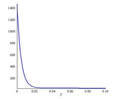
$t_{h 1}=33 e^{-1.35310^{-15} T}+0.000767 e^{-435.86 T}$$+1439 e^{-229.52 T}$
$t_{c 1}=33 e^{-1.35310^{-15} T}+1.36510^{-10}$$-2.60710^{-10} e^{-229.51 T}$
$t_{h 2}=1439 e^{-229.52 T}+0.0003877 e^{-435.86 T}$$+33 e^{-3.38510^{-16} T}$
$t_{c 2}=-6.518610^{-11} e^{-229.51 T}+3.396510^{-11} e^{-435.86 T}$$+33 e^{-3.38510^{-16} T}$
The obtained equations are graphically shown in Figures 1 and 2.
Figure 1. Cold stream in parallel flow
Figure 2. Hot stream in parallel flow
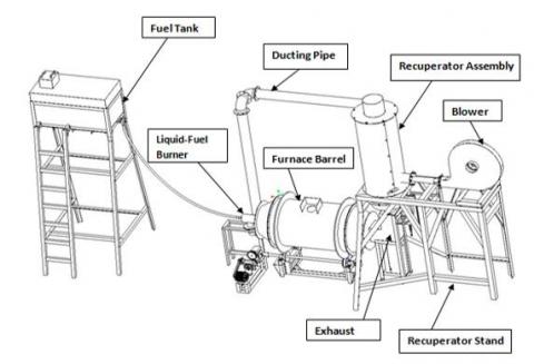
The computer aided design model of the developed heat exchanger is as shown in Figure 3 while samples of the pictures taken during the actual fabrication /development are shown in Plates 1 to 9. The CAD model of the assembled recuperator installed with a 300kg capacity rotary melting furnace is shown in Figure 4 The computer aided design was done through the use of PTC Creo parametric design modeller and materials selection was equally aided with the use of CES EduPack (Granta Design) which is a versatile computer aided materials selection tool. A typical candidate material as selected via CES EduPack 2013 is wrought and annealed Austenitic Stainless Steel (AISI 310) for all the component parts of the heat exchanger including the ducting pipes while only the outermost housing used to cover the lagging material and the Recuperator stand were constructed with mild steel.
Further thermal analysis was done both through the simulation mode of the PTC Creo parametric design modeller and COMSOL Multiphysics. PTC Creo simulation convergence is obtained by increasing the order of the interpolating polynomials on each element while COMSOL Multiphysics uses classic approach of low order interpolating polynomials of each element [19]. Figure 5 shows the close-up discretized recuperator used for the thermal analysis through Finite Elements Analysis (FEA) while Figures 6 and 7 show the Thermal Load and Simulation results respectively. The sectioned recuperator in Figure 6 showing the thermal load operating at a steady-state depicts the dependence of the thermal response to the heat loads based on the prescribed temperatures. The post-processed graphical illustration of the thermal performance characteristic of the recuperator is shown in Figure 7. The corresponding mesh statistics is shown in Table 1. The FEA process involves dividing the geometry into several simpler shapes, called finite elements. Each element and the corresponding shape of the domain is described by nodal points. The thermal analysis was done by using the Turbulent Fluid-Thermal Interaction to model a conjugate heat transfer phenomenon.
Table 1. Recuperator discretization statistics
|
Degrees of freedom |
183,200 |
|
Mesh points |
11,332 |
|
No of elements |
21,892 |
|
Triangular elements |
21,892 |
|
Quadrilateral elements |
0 |
|
Boundary elements |
2,668 |
|
Vertex elements |
46 |
|
Minimum element quality |
0.626 |
|
Element area ratio |
0.002 |
Figure 3. (a) Recuperator FEA Model Representation with Boundary Conditions; (b) Recuperator Assembly showing two halves of the outer housing bolted; (c) Recuperator Assembly showing one-half of the outer housing exposing the outer casing; (d) Sectional View of the Recuperator Assembly showing inner tube and outer shell
Figure 4. Developed recuperative heat exchanger in a 300kg capacity rotary furnace
One major assumption in analyzing the recuperator is that there is no energy loss to the environment during operation and that the exchanger has reached steady state [20].
There was a set-up of the relevant application modes with necessary couplings, in order to make it easy to model the fluid-thermal interaction. Eq. (12) shows the effective thermal conductivity, keff, used. That is,
$k_{e f f}=k+k_{T}$ (12)
where, k is the thermal conductivity of the fluid and $k_{T}=C_{p} \eta_{T}$ is the conductivity associated with turbulence and $\eta_{T}$ is the turbulent dynamic viscosity while Cp is the heat capacity.
Figure 5. Close-up of discretized recuperative heat exchanger
Figure 6. Developed recuperator's thermal load simulation
Figure 7. Thermal analysis of radiation-type recuperator
Plate 1: Recuperator outer casing & half covering drum
Plate 2: Recuperator inner radiant tube
Plate 3: Body-filled recuperator assembly
Plate 4: Recuperator assembly being tested for positioning
Plate 5: Recuperator assembly being lagged
Plate 6: Lagged recuperator assembly
Plate 7: Recuperator assembly installation in Progress - 1
Plate 8: Recuperator assembly installation in Progress - 2
Plate 9: Furnace being test run with recuperator (Temperature being measured with optical pyrometer)
This work has been able to provide useful insight in the design and thermal analysis of a recuperator used in a liquid fuel fired melting furnace with rotary furnace being used as a typical example. A better understanding of the thermal conditions of the system has been established. Usage of recuperative heat exchanger in the operation of a liquid-fuel fired melting furnace is very essential and desirable. A major reason for this is the fact that a unit of recovered physical heat from the waste gases which is recycled back into the furnace with heated air through a recuperator has more usefulness than a corresponding unit of chemical heat produced in the furnace through combustion of fuel because the heat obtained from the preheated air contains no heat losses with waste gases. This makes the value of a unit of physical heat to be greater at a lower coefficient of fuel utilization and higher temperature of waste gases.
Another advantage of recycling the waste heat through recuperative heat exchanger is environmental friendliness of the operation. The presence of hazardous and poisonous Carbon Monoxide in the combustion process is almost totally eliminated. An evidence of this is the blue flame obtainable from the operation when using the recuperator which signifies completeness of combustion. In addition, lagging the ducting pipes also serves as noise absorber apart from its primary role of preventing heat loss thereby making the operating environment friendlier.
Even though the analysis has been done for a parallel flow, it can however be adapted for a counter-current flow as well.
[1] Cottrell, A. (2019). An Introduction to Metallurgy. 2nd ed. London: CRC Press. https://doi.org/10.1201/9780429293917
[2] Kazantsev, L. (1997). Industrial Furnaces. Moscow: MIR Publishers.
[3] EMDI. (2008). Working Manual of EMR-100 Rotary Furnace. Engineering Materials Development Institute, Akure, Nigeria.
[4] Khanna, O. (2005). A Text Book of Foundry Technology. New Delhi: Dhanpat Rai Publications Ltd.
[5] Kuppan, T. (2000). Heat Exchanger Design Handbook. U.S.A: Marcel Dekker, Inc.
[6] Lv, Z., Liu, K., Qiu, J., Ma, G. (2018). A study on experiment and numerical simulation of heat exchanger in heating furnace, Metalurgija, pp. 62-66.
[7] Kapjor, A., Huzvar, J., Ftorek, B., Smatanova, H. (2014). Analysis of the heat transfer from horizontal pipes at natural convection. AIP Conference Proceeding, 1608(1). https://doi.org/10.1063/1.4892707
[8] Edward, H. (2000). Mechanical Engineer’s Reference Book, 12th ed. Great Britain: the Bath Press.
[9] Oyelami, A., Adejuyigbe, S. (2006). The design of a radiation-recuperative heat exchanger for a 200kg capacity rotary furnace. Assumption University Journal of Technology, 10(2): 93-100.
[10] Kern, D. (1984). Process Heat Transfer. Auckland: McGraw-Hill.
[11] Alan, J. (1984). Heat Transfer, 4th ed. London: Collier Macmillan.
[12] Gavlas, S., Lenhard, R., Jandačka, J. (2013). Design and numerical simulation of the heat exchanger for heat recovery system with melting furnaces for melting secondary aluminums. EPJ Web of Conferences, 45: 01033. https://doi.org/10.1051/epjconf/20134501033
[13] Dryden, I. (1982). The Efficient Use of Energy, Butterworth & Co Ltd.
[14] Brandt, C., Schüler, N., Gaderer, M., Kuckelkorn, J.M. (2014). Development of a thermal oil operated waste heat exchanger within the off-gas of an electric arc furnace at steel mills. Applied Thermal Engineering, 66(1-2): 335-345. https://doi.org/10.1016/j.applthermaleng.2014.02.003
[15] Krivadin, V., Markov, B. (1980). Metallurgical Furnaces. Moscow: MIR Publishers.
[16] Oyelami, A., Adejuyigbe, S.O.O., Olusunle, S.B. (2014). Computational modeling of temperature distribution of streams in recuperative heat exchanger. Journal of Emerging Trends in Engineering and Applied Sciences (JETEAS), 5(8): 164-169.
[17] Robert, H., Don, W. (1998). Chemical Engineering Handbook. Australia: McGraw-Hill.
[18] Engineering Tool. (2019). [Online]. Available: http://www.engineeringtoolbox.com/convective-heat-transfer-d_430.html.
[19] Oyelami, A., Ogunkoya, A., Ogundare, O., Olunlade, B. (2012). Finite elements analysis of weldments with H- and P-elements of differing orders of interpolating polynomials. The Pacific Journal of Science and Technology, 13(1): 67-77.
[20] Oyelami, A., Adejuyigbe, S. (2007). Software development for the design of a recuperator-incorporated rotary furnace. Modelling, Measurement and Control Journal, 76(1-13).