Amir Mahdi Tahsini
© 2020 IIETA. This article is published by IIETA and is licensed under the CC BY 4.0 license (http://creativecommons.org/licenses/by/4.0/).
OPEN ACCESS
In the present study, the similarity conditions in the proton exchange membrane fuel cells are investigated and the scaling effect on the polarization curve is analyzed. The steady-state two-dimensional, isothermal single-phase, and multi-species system of flow field's governing equations are utilized besides the ionic and electric potentials to predict numerically the fuel cell operation. Here, the finite-volume and cell-centered method is used as a numerical scheme. It is concluded that the similarity may exist in the performance of the fuel cells by considering some requirements. The results show that the scaling up the fuel cell with scaling size of SC makes the total current density SC times the based one, and the potential fields of the base and scaled fuel cells are similar. In addition, the effect of geometric scaling on different regions of the polarization curve is investigated for non-similar condition which shows that scaling-down the fuel cell amplifies the mass transport limiting region, and increases somewhat its maximum total current density.
geometric scaling, numerical simulation, PEM fuel cell, polarization curve, similarity condition
The chemical energy is directly converted into electricity in the fuel cells, so the fuel cells require the continuous sources of the fuel and oxidizer mass flow rate to sustain the chemical reactions. They are low-emission and low-noise devices with high energy efficiencies, and are being used nowadays in some different applications. Many researches have been carried out experimentally or numerically on the proton exchange membrane fuel cells (PEMFC) in recent years.
Gurau et al. [1] developed a model to predict the polarization curve (cell potential vs. total current density) of the PEMFCs by using steady-state and single-phase assumptions. Singh et al. [2] used similar way to predict the influence of co-flow and counter–flow fuel and oxidizer streams on the cell's limiting current. Dutta et al. [3] developed a steady-state single-phase model to simulate the straight channel PEMFCs and studied the effect of membrane thickness on the current density profiles [4].
Hsing and Futerko [5] predicted the dependence of water product leaving the anode on the current density and cell temperature. Natarajan and Nguyen [6] developed a transient two-phase mathematical model to study the dynamics of liquid water at low and high current densities. Wang et al. [7] performed similar study and illustrated the border between single-phase and two-phase regimes and studied the effect of air inlet velocity on this border. You and Liu [8] used a two-phase model to study the effect of working current density on the liquid saturation in PEM fuel cells.
Chu et al. [9] investigated the effect of the porosity of gas diffuser layer’s on the polarization curve. Burning and Djilali [10] studied the influence of inlet pressure and working temperature on the polarization curve by numerical simulations [11]. Hu et al. [12] developed a two-phase model to analyze the water content distribution in the PEM fuel cells. Hu et al. [13] studied the polarization curve with some specific configurations.
Lum and McGuirk [14] investigated the effects of channel length, electrode thickness, and oxidant concentration on fuel cell performance by numerical analysis. Ying et al. [15] and Inoue et al. [16] analyzed the channel configuration impacts on polarization curve. Lin et al. [17] performed the optimization method to find the optimal combination of the channel width ratio and the porosity. Yan et al. [18] proposed a tapered configuration for channels to improve the efficiency of the PEMFCs.
Meng [19-21] developed a transient model to predict the response of the fuel cell to a sudden change of the voltage. Secanell et al. [22] used a numerical optimization method to maximize the current density for a given voltage. Shimpalee and Van Zee [23] investigated the effects of geometry and flow direction, and Cheng et al. [24] studied the influence of catalyst layer composition on the performance of the PEMFCs.
Wu et al. [25] performed a numerical study of the transient operation during startup process. Jang et al. [26] numerically studied the influence of the flow field configurations on the performance. Gurau and Mann [27] overviewed the mathematical issues of the multiphase transport in PEMFCs. Min [28] used a two-phase model to study the cathode humidity effect and water saturation distribution on the performance. Fontana et al. [29] investigated the effect of channel flow geometry on the polarization curve of the PEM fuel cells.
Massonnat et al. [30] numerically predicted the time-variation of the voltage and temperature. Mancusi et al. [31] investigated the two-phase flow patterns in the gas channels for tapered configure ration. Chaudhary et al. [32] used a numerical procedure to predict time-variation of membrane water content. Perng and Wu [33] studied the effect of trapezoid baffle geometry on the net power. Bao and Bessler [34] numerically analyzed the impact of the long flow channels on polarization curve of the PEM fuel cells.
Kongkanand et al. [35] improved the fuel cell performance by using low Pt content catalysts. Ghanbarian and Kermani [36] numerically studied the effect of flow channel indentation on the performance. Duad et al. [37] presented a comprehensive review on the control system of the PEM fuel cells with special attention on avoiding fuel starvation. Wilberforce et al. [38] numerically optimized the flow channel configure rations to reduce the pressure drop. Fergani [39] presented the optimization scheme to define the optimum values of PEMFCs unknown parameters to ensure proper modeling, simulation and control. Huo et al. [40] proposed an analytical multiphase model for the PEM fuel cell to investigate the self-startup behavior from subfreezing temperatures.
Although numerous researches have been performed to investigate and optimize the various physicochemical processes, the scaling and similarity of PEM fuel cells are much less discussed. Scaling and similarity are important topics where the impacts of geometric scaling on the polarization curves and the conditions in which the similarity occurs are the questions at those topics. True similarity implies that the different processes occurring in two different-scale systems are of similar fashion. The answer to such questions will be helpful in an analysis, prediction and experimentation especially when the costs of experiment or times of analysis are too high. The objective of the present work is to specify the similarity requirements and predicting the scale effects on PEM fuel cells.
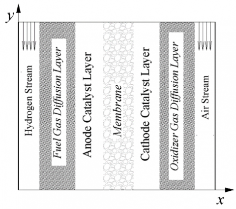
In the present study, the two-dimensional PEM fuel cell is considered as it is schematically shown in Figure 1.
Figure 1. Schematic configuration of PEMFC
The flow field is assumed to be steady-state, single-phase, and isothermal. So, the governing equations of the multi-species system are presented in conservation form as:
$\frac{\partial \left( L+{{L}_{v}} \right)}{\partial x}+\frac{\partial \left( G+{{G}_{v}} \right)}{\partial y}=ST$ (1)
Here:
$L=\left[\begin{array}{l}\rho u \\ \rho u u+p \\ \rho u v \\ \rho u m_{j}\end{array}\right] G=\left[\begin{array}{l}\rho v \\ \rho v u \\ \rho v v+p \\ \rho v m_{j}\end{array}\right] L_{v}=\left[\begin{array}{l}0 \\ -\tau_{x x} \\ -\tau_{x y} \\ -\rho D_{e f f} m_{j x}\end{array}\right]$
$G_{v}=\left[\begin{array}{l}0 \\ -\tau_{y x} \\ -\tau_{y y} \\ -\rho D_{e f f} m_{j y}\end{array}\right] S T=\left[\begin{array}{l}\sum \dot{\omega}_{j} \\ 0 \\ 0 \\ \dot{\omega}_{j}\end{array}\right]$ (2)
where,
${{D}_{eff}}=D\,{{\varepsilon }^{1.5}}$ (3)
There are four different species in the flow field which their mass rate of change is defined as:
$\begin{align} & {{{\dot{\omega }}}_{{{H}_{2}}}}=-\frac{2{{j}_{A}}}{2F}\,\,\,\,\,\,\,{{{\dot{\omega }}}_{{{O}_{2}}}}=\frac{32{{j}_{C}}}{4F}\,\,\,\,\,\,\, \\ & {{{\dot{\omega }}}_{{{N}_{2}}}}=0\,\,\,\,\,\,\,{{{\dot{\omega }}}_{{{H}_{2}}O}}=-\frac{18{{j}_{C}}}{2F} \\ \end{align}$ (4)
The exchange current densities are computed here by using the following equations:
$\begin{align} & {{j}_{A}}={{j}_{A}}_{ref}{{\left( \frac{{{c}_{{{H}_{2}}}}}{{{c}_{{{H}_{2}}}}_{ref}} \right)}^{{{r}_{a}}}}\left[ \exp \left( \frac{{{\alpha }_{A,A}}F{{\eta }_{A}}}{RT} \right)-\exp \left( -\frac{{{\alpha }_{A,C}}F{{\eta }_{A}}}{RT} \right) \right] \\ & {{j}_{C}}={{j}_{C}}_{ref}{{\left( \frac{{{c}_{{{O}_{2}}}}}{{{c}_{{{O}_{2}}}}_{ref}} \right)}^{{{r}_{c}}}}\left[ \exp \left( \frac{{{\alpha }_{C,A}}F{{\eta }_{C}}}{RT} \right)-\exp \left( -\frac{{{\alpha }_{C,C}}F{{\eta }_{C}}}{RT} \right) \right] \\ \end{align}$ (5)
The over-potentials are defined as:
$\eta_{A}=\phi_{e}-\phi_{p}$
$\eta_{C}=\phi_{e}-\phi_{p}-U_{o}$ (6)
where, [32]
${{U}_{o}}=1.23-9\times {{10}^{-4}}\left( T-298 \right)$ (7)
Besides the flow field, the equations for electric and ionic potentials are:
$\nabla \cdot\left(-\sigma \nabla \phi_{e}\right)=S_{e}$
$\nabla \cdot\left(-\kappa \nabla \phi_{p}\right)=S_{p}$ (8)
Here:
$S_{e}=\left\{\begin{array}{ll}-j_{A} & \text { at Anode } \\ -j_{C} & \text { at Cathode }\end{array}\right.$
$S_{p}=\left\{\begin{array}{ll}j_{A} & \text { at Anode } \\ j_{C} & \text { at Cathode }\end{array}\right.$ (9)
The electric potential equation is solved in the gas diffusion layers (GDL) and the catalyst layers, but the ionic potential equation is solved in the catalyst layers and the membrane. The total current density is computed by integrating the exchange current densities on the anode or cathode catalyst layers:
$I\times {{L}_{c}}=\iint\limits_{anode}{\left| {{j}_{A}} \right|dA}=\iint\limits_{cathode}{\left| {{j}_{C}} \right|dA}$ (10)
For numerical computation, the finite-volume cell-centered method is used. Viscous terms are treated using a central scheme and the inviscid fluxes are treated using an AUSM+ method. The simulation procedure has been validated using various problems and has also been utilized to study different flows where more details can be found Tahsini et al. [41-47]. The velocities and mass fractions of the species are specified as a boundary condition for inflow streams. The zero electric potential is applied on the interface of fuel channel and GDL (anode side), and the fuel cell’s working potential is applied on the interface of the oxidizer channel and GDL (cathode side) for electric potential equation. In an ionic potential equation, the zero-flux boundary condition is applied on the interfaces of GDL and the catalyst layer at both anode and cathode sides.
Table 1. Typical geometric and physical parameters of the PEMFC
|
Quantity |
Value |
|
Fuel channel thickness (m) |
1.e-4 |
|
Fuel gas diffusion layer thickness (m) |
1.e-4 |
|
Anode catalyst layer thickness (m) |
4.e-5 |
|
Membrane thickness (m) |
1.e-4 |
|
Cathode catalyst layer thickness (m) |
4.e-5 |
|
Oxidizer gas diffusion layer thickness (m) |
1.e-4 |
|
Oxidizer channel thickness (m) |
1.e-4 |
|
Channel length (m) |
6.e-2 |
|
Fuel gas diffusion layer porosity |
0.4 |
|
Anode catalyst layer porosity |
0.1 |
|
Cathode catalyst layer porosity |
0.1 |
|
Oxidizer gas diffusion layer porosity |
0.4 |
|
Electric conductivity of fuel gas diffusion layer (Sm-1) |
1.e3 |
|
Electric conductivity of anode catalyst layer (Sm-1) |
1.5e3 |
|
Electric conductivity of cathode catalyst layer (Sm-1) |
2.e3 |
|
Electric conductivity of oxidizer gas diffusion layer (Sm-1) |
3.e3 |
|
Ionic conductivity of anode catalyst layer (Sm-1) |
3. |
|
Ionic conductivity of membrane (Sm-1) |
5. |
|
Ionic conductivity of cathode catalyst layer (Sm-1) |
10. |
|
Anode reference exchange current density (Am-3) |
9.e8 |
|
Cathode reference exchange current density (Am-3) |
250. |
|
Hydrogen concentration power |
1 |
|
Oxygen concentration power |
1 |
|
Hydrogen reference concentration (k mole m-3) |
40.e-3 |
|
Oxygen reference concentration (k mole m-3) |
40.e-3 |
|
Charge transfer coefficients |
1. |
|
Working temperature (K) |
353. |
|
Inlet pressures (bar) |
1. |
|
Inlet velocities (ms-1) |
5. |
|
Oxygen mass fraction at oxidizer stream |
0.2 |
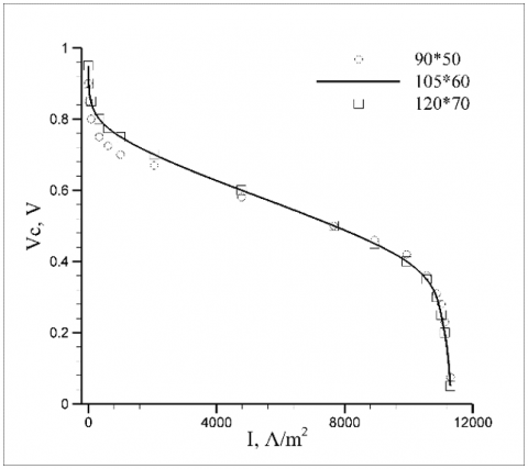
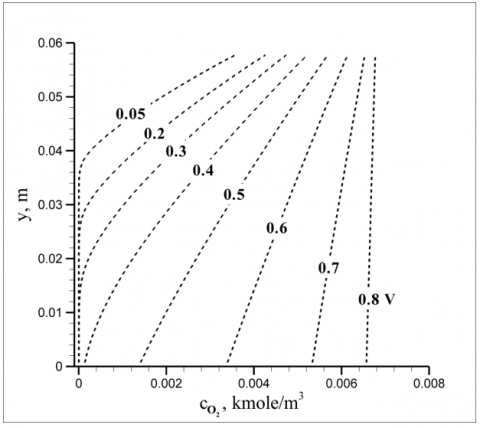
Typical geometric and physical parameters adopted here are presented in Table 1. After the grid independency studies, the grid resolution of 105×60 is used in simulations based on the polarization curve which is shown in Figure 2. The left sharp drop of the polarization curve corresponds the activation polarization, and the right sharp drop corresponds the concentration polarization. The concentration polarization region depends on the ability of the oxygen molecules to diffuse through the oxidizer gas diffusion layer into the cathode catalyst layer. At high electric currents, and especially when the inlet oxygen is diluted, the oxygen concentration level in the catalyst layer (CL) is much low and the oxygen is almost entirely consumed at the GDL-CL interface, so the rate of the reaction which consumes the electrons cannot increase anymore, and the concentration polarization region appears in the polarization curve. The limiting total current density of this PEMFC is about 11.4 kA m-2. Variations of oxygen concentration along the interface of cathode catalyst layer and oxidizer gas diffusion layer are presented for different working potentials in Figure 3. It demonstrates the downstream oxygen degradation especially for high electric currents (low voltages) that leads to the mass transport limiting behavior in the polarization curve.
Figure 2. Polarization curve of PEMFC
Figure 3. Oxygen concentration along the CL-GDL interface for different working potentials
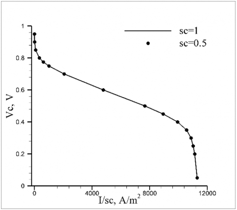
Figure 4. Similarity of the polarization curves
The operation of the PEM fuel cells is a consequence of the interactions between the flow field equations and the electric and ionic potential equations. Although a main midsection of the polarization curve is almost linear, there are two other important extreme regions which the mass transport region is entirely dependent to the flow field’s behavior (species concentration distribution) that determines the limiting total current density of the fuel cell. According to these interactions and nonlinearities, the similarity conditions for the PEMFCs are examined here.
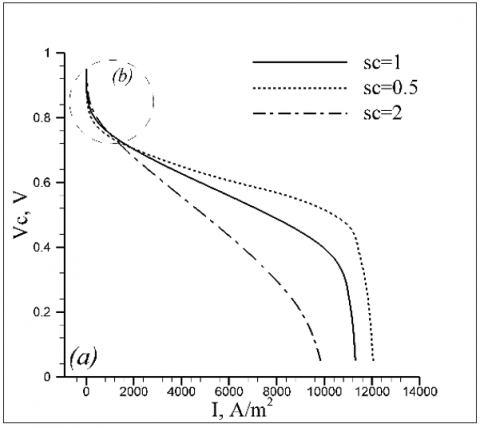
Due to the mathematics of the governing equations, the analysis shows that by exact geometric scaling of the fuel cell (scaling all dimensions) using the scale factor sc, the similarity exists if the inlet stream velocities are multiplied by sc and all diffusion coefficients ($D, \mu, \kappa, \sigma$) are multiplied by sc2. By this similarity condition, the flow fields and the potential fields of the base and scaled fuel cells are similar, and the maximum total current density of the scaled fuel cell equals the sc times the maximum total current density of the base one. In addition, the polarization curves are exactly similar in whole regions.
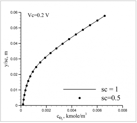
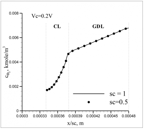
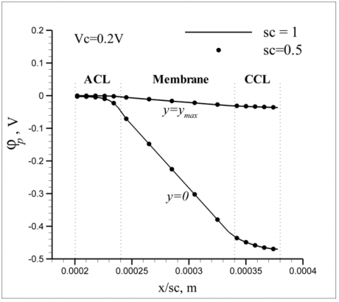
Utilizing the scale factor 0.5, the polarization curves of the base and scaled fuel cells are compared in Figure 4 that illustrates the similarity in all regions. Notice that the total current density is scaled by adopted scale factor (longitudinal axis). In addition, the profiles of the oxygen concentration and the ionic potential for the working potential of 0.2 are shown in Figures 5-7 which demonstrate the similarity of the flow and potential fields too. It is also noticed that the length-axes are scaled by adopted scale factor. It was shown in Figure 3 that at lower potentials, the concentration polarization phenomenon occurred due to insufficient gas supply, which is now illustrated that this behavior is also repeated similarly.
Figure 5. Similarity of oxygen concentration changes along the channel external wall at x=xmax
Figure 6. Similarity of oxygen concentration changes across the CL-GDL at y=ymax
Figure 7. Similarity of the potential fields
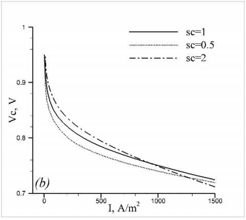
Figure 8. Polarization curves for scaled (non-similar) fuel cells, a) whole regions, b) activation region
Therefore, by scaling the fuel cell, the similarity condition is found and shown that works true. Now, another question is that what if the geometry is scaled but keeping the other parameters constant; how does the polarization curve or the maximum total current density change if the fuel cell is geometrically scaled with no change in inlet stream velocities or diffusion properties? To investigate the impacts of just geometric scaling, the considered PEMFC is scaled with no change in other quantities and the polarization curves are computed and compared in Figure 8.
The results illustrate that the geometric-scaling of the fuel cell has different impacts on different regions of the polarization curve; Scaling-up the fuel cell increases the total current density for specified potential in the activation region, and decreases it in other regions, and the scaling-down influence is opposite. In addition, the concentration polarization region is magnified by scaling-down the fuel cell because although it reduces the channel length and one may guess that it attenuates the species concentration effect, the impact of geometric change in cross-direction is dominant and the mass transport limiting region is amplified in this situation. Finally, it should be noticed that the maximum total current density of the scaled fuel cells isn’t changed substantially in comparison with scaling ratio, and it is somewhat increased for the downscaled fuel cells.
Numerical investigations of the proton exchange membrane fuel cells are performed here utilizing the steady-state and multi-species system of equations. The existence of the similarity in the fuel cell's operation is proven and it is demonstrated that applying the similarity conditions, the flow fields, potential fields, and the polarization curves of the base and scaled fuel cells are similar. The similarity condition is scaling the inlet stream velocities by the scale factor and scaling all diffusion coefficients by the square of the scale factor, besides the exact geometric scaling of the fuel cell's dimensions. In addition, the impacts of geometric-scaling are studied without applying the similarity conditions, and it is concluded that it affects the regions of the polarization curve differently, and scaling-down the fuel cell unexpectedly amplifies the mass transport limiting region, and also increases somewhat its maximum total current density.
|
cj |
concentration of species j |
|
Deff |
effective mass diffusion coefficient |
|
F |
Faraday constant |
|
I |
total current density |
|
$j_{\text {ref }}$ |
reference exchange current density |
|
Lc |
channel length |
|
mj |
mass fraction of species j |
|
p |
pressure |
|
R |
universal gas constant |
|
sc |
scale factor |
|
T |
temperature |
|
u |
axial velocity |
|
Uo |
open circuit potential |
|
Vc |
working potential |
|
v |
lateral velocity |
|
α |
charge transfer coefficient |
|
ε |
porosity |
|
$\eta_{a, c}$ |
anode and cathode over-potentials |
|
κ |
ionic conductivity |
|
$\varphi_{e, p}$ |
electric and ionic potentials |
|
σ |
electric conductivity |
|
$\dot{\omega}_{j}$ |
mass rate of production of species j |
[1] Gurau, V., Liu, H., Kakac, S. (1998). Two-dimensional model for proton exchange membrane fuel cells. AIChE Journal, 44(11): 2410-2422. https://doi.org/10.1002/aic.690441109
[2] Singh, D., Lu, D., Djilali, N. (1999). A two-dimensional analysis of mass transport in proton exchange membrane fuel cells. International Journal of Engineering Science, 37(4): 431-452. https://doi.org/10.1016/S0020-7225(98)00079-2
[3] Dutta, S., Shimpalee, S., Van Zee, J. (2000). Three-dimensional numerical simulation of straight channel PEM fuel cells. Journal of Applied Electrochemistry, 30: 135-146. https://doi.org/10.1023/A:1003964201327
[4] Shimpalee, S., Dutta, S. (2000). Numerical prediction of temperature distribution in PEM fuel cells. Numerical Heat Transfer, 38(2): 111-128. https://doi.org/10.1080/10407780050135360
[5] Hsing, I., Futerko, P. (2000). Two-dimensional simulation of water transport in polymer electrolyte fuel cells. Chemical Engineering Science, 55(19): 4209-4218. https://doi.org/10.1016/S0009-2509(00)00066-X
[6] Natarajan, D., Nguyen, T. (2001). A two-dimensional, two-phase, multi-component, transient model for the cathode of a proton exchange membrane fuel cell using conventional gas distributors. Journal of Electrochemical Society, 148(12): 1324-1335. https://doi.org/10.1149/1.1415032
[7] Wang, Z., Wang, C., Chen, K. (2001). Two-phase flow and transport in the air cathode of proton exchange membrane fuel cells. Journal of Power Sources, 94: 40-50. https://doi.org/10.1016/S0378-7753(00)00662-5
[8] You, L., Liu, H. (2002). A two-phase flow and transport model for the cathode of pem fuel cells. International Journal of Heat and Mass Transfer, 45(11): 2277-2287. https://doi.org/10.1016/S0017-9310(01)00322-2
[9] Chu, H., Yeh, C., Chen, F. (2003). Effects of porosity change of gas diffuser on performance of proton exchange membrane fuel cell. Journal of Power Sources, 123(1): 1-9. https://doi.org/10.1016/S0378-7753(02)00605-5
[10] Berning, T., Djilali, N. (2003). Three-dimensional computational analysis of transport phenomena in a PEM fuel cell-A parametric study. Journal of Power Sources, 124(2): 440-452. https://doi.org/10.1016/S0378-7753(01)01057-6
[11] Nguyen, P., Berning, T., Djilali, N. (2004). Computational model of a PEM fuel cell with serpentine gas flow channels. Journal of Power Sources, 130: 149-157. https://doi.org/10.1016/j.jpowsour.2003.12.027
[12] Hu, M., Zhu, X., Wang, M., Gu, A., Yu, L. (2004). Three dimensional, two phase flow mathematical model for PEM fuel cell. Energy Conversion and Management, 45(11-12): 1861-1916. https://doi.org/10.1016/j.enconman.2003.09.022
[13] Hu, G., Fan, J., Chen, S., Liu, Y., Cen, K. (2004). Three-dimensional numerical analysis of proton exchange membrane fuel cells with conventional and interdigitated flow fields. Journal of Power Sources, 136(1): 1-9. https://doi.org/10.1016/j.jpowsour.2004.05.010
[14] Lum, K., McGuirk, J. (2005). Three-dimensional model of a complete polymer electrolyte membrane fuel cell–model formulation, validation and parametric studies. Journal of Power Sources, 143(1-2): 103-124. https://doi.org/10.1016/j.jpowsour.2004.11.032
[15] Ying, W., Yang, T., Lee, W., Ke, J., Kim, C. (2005). Three-dimensional analysis for effect of channel configuration on the performance of a small air-breathing proton exchange membrane fuel cell. Journal of Power Sources, 145(2): 572-581. https://doi.org/10.1016/j.jpowsour.2005.02.066
[16] Inoue, G., Matsukuma, Y., Minemoto, M. (2006). Effect of gas channel depth on current density distribution of polymer electrolyte fuel cell by numerical analysis including gas flow through gas diffusion layer. Journal of Power Sources, 157(1): 136-152. https://doi.org/10.1016/j.jpowsour.2005.08.004
[17] Lin, H., Cheng, C., Soong, C., Chen, F., Yan, W. (2006). Optimization of key parameters in the proton exchange membrane fuel cell. Journal of Power Sources, 162(1): 246-254. https://doi.org/10.1016/j.jpowsour.2006.06.054
[18] Yan, W., Liu, H., Soong, C., Chen, F., Cheng, C. (2006). Numerical study on cell performance and local transport phenomena of pem fuel cells with novel flow field designs. Journal of Power Sources, 161(2): 907-919. https://doi.org/10.1016/j.jpowsour.2006.05.007
[19] Meng, H. (2007). A three-dimensional mixed-domain pem fuel cell model with fully-coupled transport phenomena. Journal of Power Sources, 164(2): 688-696. https://doi.org/10.1016/j.jpowsour.2006.10.086
[20] Meng, H. (2007). A two-phase non-isothermal mixed-domain PEM fuel cell model and its application to two-dimensional simulations. Journal of Power Sources, 168(1): 218-228. https://doi.org/10.1016/j.jpowsour.2007.03.012
[21] Meng, H. (2007). Numerical investigation of transient responses of a PEM fuel cell using a two-phase non-isothermal mixed-domain model. Journal of Power Sources, 171(2): 738-746. https://doi.org/10.1016/j.jpowsour.2007.06.029
[22] Secanell, M., Carnes, B., Suleman, A., Djilali, N. (2007). Numerical optimization of proton exchange membrane fuel cell cathodes. Electrochimica ACTA, 52(7): 2668-2682. https://doi.org/10.1016/j.electacta.2006.09.049
[23] Shimpalee, S., Van Zee, J. (2007). Numerical studies on rib & channel dimension of flow-field on PEMFC performance. International Journal of Hydrogen Energy, 32(7): 842-856. https://doi.org/10.1016/j.ijhydene.2006.11.032
[24] Cheng, C., Lin, H., Lai, G. (2007). Numerical prediction of the effect of catalyst layer nafion loading on the performance of PEM fuel cells. Journal of Power Sources, 164(2): 730-741. https://doi.org/10.1016/j.jpowsour.2006.11.039
[25] Wu, H., Li, X., Berg, P. (2007). Numerical analysis of dynamic processes in fully humidified PEM fuel cells. International Journal of Hydrogen Energy, 32: 2022-2031. https://doi.org/10.1016/j.ijhydene.2006.09.046
[26] Jang, J., Yan, W., Li, H., Tsai, W. (2008). Three-dimensional numerical study on cell performance and transport phenomena of pem fuel cells with conventional flowfields. International Journal of Hydrogen Energy, 33(1): 156-164. https://doi.org/10.1016/j.ijhydene.2007.09.005
[27] Gurau, V., Mann, J. (2009). A critical overview of computational fluid dynamics multiphase models for proton exchange membrane fuel cells. SIAM Journal of Applied Mathematics, 70(2): 410-454. https://doi.org/10.1137/080727993
[28] Min, C. (2010). A novel three-dimensional, two-phase and non-isothermal numerical model for proton exchange membrane fuel cell. Journal of Power Sources, 195(7): 1880-1887. https://doi.org/10.1016/j.jpowsour.2009.10.035
[29] Fontana, E., Mancusi, E., Silva, A. (2011). Study of the effects of flow channel with non-uniform cross-sectional area on PEMFC species and hat transfer. International Journal of Heat and Mass Transfer, 54(21-22): 4462-4472. https://doi.org/10.1016/j.ijheatmasstransfer.2011.06.037
[30] Massonnat, P., Gao, F., Roche, R., Paire, D., Bouquain, D., Miraoui, A. (2014). Multiphysical, multidimensional real-time PEM fuel cell modeling for embedded applications. Energy Conversion and Management, 88: 554-564. https://doi.org/10.1016/j.enconman.2014.08.062
[31] Mancusi, E., Fontana, E., Souza, A. (2014). Numerical study of two-phase flow patterns in the gas channel of PEM fuel cells with tapered flow field design. International Journal of Hydrogen Energy, 39(5): 2261-2273. https://doi.org/10.1016/j.ijhydene.2013.11.106
[32] Chaudhary, S., Sachan, V., Bhattacharya, P. (2014). Two dimensional modelling of water uptake in proton exchange membrane fuel cell. International Journal of Hydrogen Energy, 39(31): 17802-17818. https://doi.org/10.1016/j.ijhydene.2014.08.128
[33] Perng, S., Wu, H. (2015). A three-dimensional numerical investigation of trapezoid baffles effect on non-isothermal reactant transport and cell net power in a PEMFC. Applied Energy, 143: 81-95. https://doi.org/10.1016/j.apenergy.2014.12.059
[34] Bao, C., Bessler, W. (2015). Two-dimensional modeling of a polymer electrolyte membrane fuel cell with long fow channel. Part I. Model Development. Journal of Power Sources, 275: 922-934. https://doi.org/10.1016/j.jpowsour.2014.12.045
[35] Kongkanand, A., Subramanian, N.P., Yu, Y., Liu, Z., Igarashi, H., Muller, D.A. (2016). Achieving high-power PEM fuel cell performance with an ultralow-pt-content core–shell catalyst. ACS Catalysis, 6(3): 1578-1583. https://doi.org/10.1021/acscatal.5b02819
[36] Ghanbarian, A., Kermani, M. J. (2016). Enhancement of PEM fuel cell performance by flow channel indentation. Energy Conversion and Management, 110: 356-366. https://doi.org/10.1016/j.enconman.2015.12.036
[37] Duad, W., Rosli, R.E., Majlan, E.H., Hamid, S.A.A., Mohamed, R., Husaini, T. (2017). PEM fuel cell system control: A review. Renewable Energy, 113: 620-638. https://https://doi.org/10.1016/j.renene.2017.06.027
[38] Wilberforce, T., Hassan, Z., Khatib, F.N., Makky, A., Mooney, J., Barouaji, A., Carton, J.G., Olabi, A.H. (2017). Development of bi-polar plate design of PEM fuel cell using CFD techniques. International Journal of Hydrogen Energy, 42(40): 25663-25685. https://doi.org/10.1016/j.ijhydene.2017.08.093
[39] Fergani, A. (2018). Extracting optimal parameters of pem fuel cells using salp swarm optimizer. Renewable Energy, 119: 641-648. https://doi.org/10.1016/j.renene.2017.12.051
[40] Huo, S., Jiao, K., Park, J.W. (2019). On the water transport behavior and phase transition mechanisms in cold start operation of PEM fuel cell. Applied Energy, 233-234: 776-788. https://doi.org/10.1016/j.apenergy.2018.10.068
[41] Tahsini, A.M. (2016). The influence of an optical cavity’s diamond pattern on the performance of the gas dynamic lasers, accepted for publication. The Aeronautical Journal, 120(1234): 1932-1942. https://doi.org/10.1017/aer.2016.95
[42] Tahsini, A.M. (2016). Detonation wave attenuation in dust-free and dusty air. Journal of Loss Prevention in the Process Industries, 39: 24-29. https://doi.org/10.1016/j.jlp.2015.11.006
[43] Tahsini, A.M., Tadayon Mousavi, S. (2015). Investigating the supersonic combustion efficiency for the jet-in-cross-flow. International Journal of Hydrogen Energy, 40(7): 3091-3097. https://doi.org/10.1016/j.ijhydene.2014.12.124
[44] Tahsini, A.M. (2014). Parametric study of the effect of exothermic coating properties on blunt nose drag reduction in hypersonic flights. Journal of Aerospace Engineering IMechE, 228(9): 1461-1465. https://doi.org/10.1177/0954410013490849
[45] Tahsini, A.M. (2014). Transient burning of non-charring materials in boundary layer diffusion flames. Journal of Aerospace Engineering IMechE, 228(4): 586-593. https://doi.org/10.1177/0954410013478357
[46] Tahsini, A.M. (2013). Heat release effects on drag reduction in high speed flows. International Journal of Heat and Mass Transfer, 57(2): 657-661. https://doi.org/10.1016/j.ijheatmasstransfer.2012.10.064
[47] Tahsini, A.M. (2012). Piloted ignition of solid fuels in turbulent back-step flows. Aerospace Science and Technology, 18(1): 8-14. https://doi.org/10.1016/j.ast.2011.03.008