Khaled M.K. Pasha* | Mohamed Mahmoud El-Fawal
© 2020 IIETA. This article is published by IIETA and is licensed under the CC BY 4.0 license (http://creativecommons.org/licenses/by/4.0/).
OPEN ACCESS
It is required to investigate the economy of the performance of four suggested heat exchanger designs. The economy criteria are expressed by the ratio of the Nusselt number, Nu, and the pressure loss coefficient, $\Delta P^{*}$. The four patterns are; rectangular, zigzag, spiral, and narrow-spiral. The air passages of each one of the four types have the same cross-section area and air passage length. Also, the inlet air temperature and flow rate for both; the air and water are the same in the four types. The narrow-spiral pattern has an equal passage thickness for both air and water. Reynolds number, Re, of values; 2535, 7606, 12677, 17748, 20284, 22819, 25355, (based on the hydraulic diameter of the cross-section) are investigated. For validation, the rectangular pattern type was checked experimentally, and the results were close to those of the prediction. For all values of the Reynolds number, the suggested narrow-spiral pattern exhibited the highest values of $\mathrm{Nu} / \Delta P^{*}$. At the Reynolds number of 25355, the ratio, $\mathrm{Nu} / \Delta P^{*}$ could achieve a value of about 15.74 for the narrow-spiral type. For each suggested pattern, ($\mathrm{Nu} / \Delta P^{*}$) and Re are correlated in a suitable formula.
heat exchanger, energy economy, Nusselt, pressure losses, passage pattern
Heat exchangers constitute essential components in a wide range of applications. The main goal of the design process for any heat exchanger is to transfer the highest possible thermal energy between the two fluids with minimum pressure losses. To achieve an efficient heat exchanger design that allows larger heat transfer, it is required first to review the previous studies and designs in this field. Next, a careful analysis is made of the drawbacks of these previous designs, then, to suggest and investigate new geometries that are believed to maximize the heat transfer. Many heat exchanger designs are available in the literature and all of them included different methods to maximize the heat transfer. A brief survey of their work will be illustrated in the following article.
1.1 Review of previous work
Hasan et al. [1] numerically investigated the axial heat conduction in a right triangular microchannel heat exchanger under different conditions. They reported that the parameters that affect the axial heat conduction in an isosceles right triangular microchannel heat exchanger are: conductivity ratio Kr, Reynolds number Re, hydraulic diameter Dh, and the wall thickness, ts. The axial heat conduction was increased with Kr to the value of 10, and beyond this value, it tends to zero. Hammadi [2] developed a mathematical model, and numerically predicted the behavior of the solar humidifier and underground heat exchanger in the transient mode. He reported that the amount of produced water depends on the solar intensity throughout the year, and as quantitative analysis, 0.2 m diameter pipe buried in the ground at 1 m depth needs about 50 m length to complete the condensation process, and the maximum daily productivity for unit length was found 8.96 kg when the pipe diameter is 0.55 m. De et al. [3] designed of shell and tube type heat exchanger with a helical baffle and compared it with a straight baffle with CFD analysis using commercial software tools. Their model contained 7 Copper tubes. The flow pattern in the shell side of the heat exchanger with continuous helical baffles are forced to be rotational and helical due to the geometry of the continuous helical baffles, which results in a significant increase in heat transfer coefficient per unit pressure drop in the heat exchanger. Cucumo et al. [4] presented a 3D numerical solution of two real shell-and-tube heat exchangers, with a different type of baffles, segmental, and pseudo-helical through the use of commercial codes, to evaluate the influence of the baffles type on heat exchanger performance. Their heat exchangers are with pseudo-helical baffles inclined by 7°, 20°, 30°, and 40°. Their increased heat transfer results are compared and verified with published correlations. Belloufi et al. [5] investigated the thermal performances of an earth air heat exchanger (EAHE) under transient conditions in cooling mode. They used a PVC pipe of 53.16 m long and a 110 mm diameter buried at 3 m depth is used. Their continuous operation mode has no remarkable effect on the outlet air temperature and thus on the EAHE performances during all 71 hours. Kailash et al. [6] investigated the pipe heat exchanger using fins. They concluded that for Re= 17161.05 and with a semi-circular fin the heat transfer coefficient decreased by 300%. Besides, for a fluid rate of 0.3832 kg/sec, the heat transfer decreased by 220% of that with a simple tube.
Jathar et al. [7] investigated the double pipe type with counter and parallel flow, (CF and PF), and different types of slot washers. They reported that the heat transfer coefficient increased with Re, and its maximum value was obtained when using the CF with 2-slot and the PF with 2-slot washer. The heat transfer coefficient was enhanced by 265%. Stephenraj and Sathishkumar [8] simulated the flow for different baffle arrangement in the heat exchangers. The maximum heat transfer was obtained when they inclined the baffles at an angle of 35o. They reported that using water alone in their model gives a better performance than that of the previous work where they used CuO added to water. Singh and Sehgal [9] experimentally studied the shell-and-tube type at ranges of Re between 303 and 1516. They reported that the heat transfer coefficient, h, the Nusselt number Nu, and the pressure losses increased with Re for the hot and cold inlet fluid. But the temperature constants $\xi$ and $\omega$ decreased with Re. Parmar et al. [10] analyzed a heat exchanger of type “shell and tube”. They used the Bell Delaware methods and calculated both; Reynold’s number and the pressure drops. They reported that the shell side pressure increased rapidly with the increase of the flow rate, and again the pressure decreased considerably because of the usage of baffles. Also, the shell side pressure increased rapidly with the Reynolds number. Dubey et al. [11] investigated the factors that affect performance. They reported that the rate of heat transfer may increase when operating below the level of critical thickness, and the cotton, wool, and tape exhibited accepted effectiveness which is affected also by the level of turbulence. Bichkar et al. [12] predicted the fluid performance of the shell side of a heat exchanger. They concluded that, if the number of baffles is increased over a certain value, the heat transfer will increase but, the pressure losses will increase considerably too. When they changed the types of baffles with maintaining the main dimensions of the helical baffles, this leads to a considerable reduction in the pressure losses.
Another trial to design an optimized heat exchanger was made by Mishra et al. [13], who used a method that depended on a Genetic Algorithm to optimize a multilayer plate type of heat exchanger. His solutions obtained by GA considerably agreed to those from the graphical method but, the total annual cost of the heat exchanger increased. Ramachandran et al. [14] studied a two-phase flow in a heat exchanger with a spiral plate. They used water and palm oil as the working fluids. They correlated the quality (X), φL, and L – M parameter. This correlation exhibited a considerable agreement with the experimental results. Jia and Hu [15] developed a 3D model of a multilayered heat exchanger of the counter-flow parallel type. They simulated the model using COMSOL with oil and water. Their results of the temperature, velocities, and pressure established guide data to design an optimal heat exchanger.
1.2 Extracting the idea
As seen from the above, in most of the previous researches there is an investigation of a heat exchanger design in which, every “position” in the first fluid passage transfers heat to a unique position in the second fluid passage. During the flow of the hot fluid, its temperature decreases and the heat transfer capability decreases too. The temperature of the cold fluid increase and its capability to receive heat decreases.
So, it leaves its passage with a lower portion of the available energy in the hot fluid. This led us to suggest some design geometries that contain longer passages for both fluids and allow each position in the fluid passage to exchange heat with different positions in the other fluid passage. All that in a more compact design that includes a longer interface between the two fluids and supports more heat transfer between them.
1.3 Objective of the present work
In the present work, it is required to;
suggest and investigate four geometries for a heat exchanger. The cross-sections of the fluids passages in each design have the same dimensions but, the passage patterns are different. Besides, the conditions of the working fluid are the same. So, the only investigated factor is the passage pattern of each of the four designs.
Investigate numerically the performances of the four types and after estimating the pattern that exhibited the most economic performance, an experimental investigation is executed to test the chosen type to validate the numerical results.
Suggest correlations for the four types that relate their economy to the operating conditions.
(Economy is the ratio between the non-dimensional heat transfer and the non-dimensional pressure losses).
1.4 Overview of the paper
The structure of the present paper is as follows;
a) An introduction that demonstrates the importance of the subject, previous work as a guide to the present point, and the objectives of the research.
b) Brief description of the numerical work used to predict the performances of the four designs.
c) A brief description of the experimental preparations.
d) Results and discussions.
e) eConclusion.
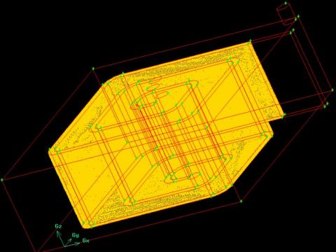
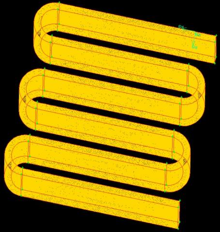
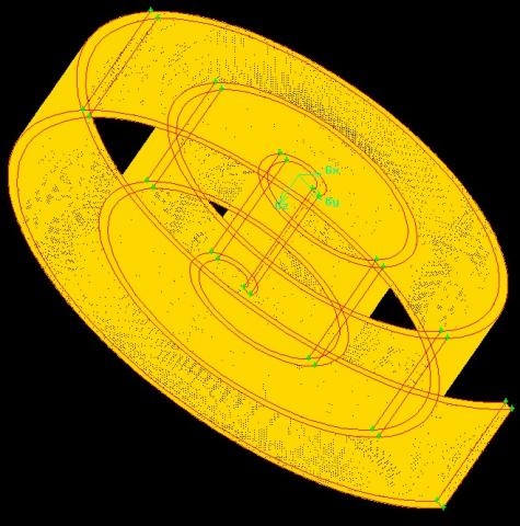
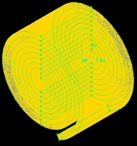
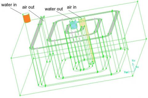
Each one of the four suggested patterns has a cross-section of 25x2 cm, and a passage length of 330 cm. the distance between any two neighboring paths is 8 cm. The four patterns were designed and meshed using the code GAMBIT with the TGrid meshing scheme and Tet/Hybrid elements type. After several preliminary tests, the stable grid resolution required 1850000, 1580000, and 1200000 elements for the rectangular, the zigzag, and the spiral patterns, respectively. The numerical simulations were performed using ANSYS 14.5 with a pressure-based solver with a standard k-epsilon model and wall function. The turbulent intensity and the turbulent viscosity ratio were limited to 5% and 10, respectively. About 1500 iterations were enough to achieve a convergence with a minimum residual of about 0.0001. Figure 1 illustrates the meshed domains of the rectangular passage type. Figure 2 illustrates the meshed domains of the zigzag passage type. Figure 3 illustrates the meshed domains of the spiral passage type. Figure 4 illustrates the meshed domains of the narrow-spiral passage type.
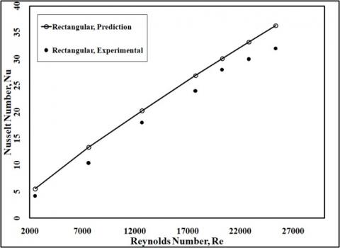
To check the reliability of our numerical model, the rectangular pattern type was tested experimentally at the same values of Reynolds number. Figure 5 illustrates the experimental and numerical results of the Nusselt number with the Reynolds number for the rectangular type. The experimental results of the Nusselt values are lower than those of the numerical runs. This may be because we used a large water flow rate to achieve the almost constant wall temperature condition but, actually, there still a slight increase in the exit wall temperature which participates in heat transfer reduction. Also, the sidewall is well insulated but this does not guarantee a zero heat loss. Besides, the used copper sheet material may include some impurities that have lower conductivity which cause a reduction in the overall heat transfer.
Figure 1. The meshed domain for the rectangular passage
Figure 2. The meshed domain for the zigzag passage
Figure 3. The meshed domain for the spiral passage
Figure 4. The meshed domain for the narrow-spiral passage
Figure 5. The experimental and numerical results of the Nusselt number with the Reynolds number for the rectangular pattern
3.1 Test rig
To check the reliability of our predictions, one of our suggested patterns was chosen to be investigated experimentally, which is the rectangular type. The air passage has length, width, and thickness of 330, 25, and 2 cm, respectively. It is made of a 1.5 mm thick copper sheet and consists of two parallel sheets that are 2cm apart.
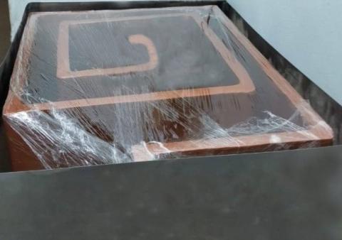
Figure 6 illustrates the design of the rectangular pattern in which, it is observed that it is a counter-flow heat exchanger type. Figure 7 illustrates the rectangular air passage, and its housing (before welding).
In each run, the air is blown in the passage using a variable-speed blower, SKU: ATO-ABL-600. It delivers a maximum flow rate of 180 m3/hr which corresponds to an inlet speed of 10 m/s according to the cross-section dimensions. It has also a built-in potentiometer to control the speed. The air velocity is checked by a Kanomax mini Pitot tube. The water is pumped by Pedrollo NGA Centrifugal Pumps that has a maximum flow rate of 21 m3/hr and its flow rate is measured using a WINGONEER YF-S201rotor sensor that works on the base of the hall effect. The pulses delivered from the sensor are taken to an Arduino and serial monitor to illustrate the rate values.
Figure 6. The detailed design of the rectangular pattern
Figure 7. The rectangular air passage, and its housing, (before installation)
The air temperatures are measured by five K-type thermocouples that are distributed through the passage and spaced 0.8m from each other and their average is taken as the air temperature. The surface temperature is calculated from the average of two thermocouples located at the beginning and end of the inner surface of the passage wall. The difference between the two thermocouples readings is small because the large cooling water flow rate and the relatively large heat capacity leads to a small variation in the surface temperature. The pressure drop through the air passage is measured by Hti-Xintai digital manometer.
3.2 Data analysis
The investigation aims to study the effects of the passage arrangement on the heat transfer and the pressure losses for heat exchangers with the same passage length and thermal conditions. The heat transfer is represented by the dimensionless Nusselt number, Eq. (2), whereas, the pressure losses are represented by the dimensionless pressure coefficient, Eq. (3). The difference between the inlet and outlet air temperatures is used to calculate the heat transfer coefficient using a simple energy balance;
$h=\rho \dot{V} \operatorname{Cp}\left(T_{i}-T_{o}\right) /\left(T_{a}-T_{s}\right)$ (1)
The Nusselt number is calculated from
$N u=h D_{h} / k$ (2)
and the pressure coefficient, $\Delta P^{*}$, is calculated as:
$\Delta P^{*}=\frac{\Delta p}{0.5 \rho U_{f}^{2}}$ (3)
where, Nu is the Nusselt number,
h is the heat transfer coefficient,
$C_{p}$, is the pressure loss coefficient,
$\Delta p$ is the pressure loss through the whole passage,
d is the hydraulic diameter of the air passage cross-section,
$\rho$, k, and U are the density, the thermal conductivity, and the average velocity, respectively of the air.
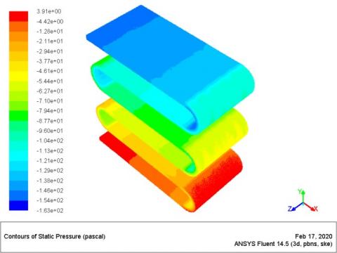
As a preliminary indication, the variation of both temperature and pressure along the passage are compared for a Reynolds number of 25355 and the comparison is illustrated in Figures 8-15. It is observed that, in the rectangle and zigzag types, the pressure decreases near the wall in the regions where the flow direction changes, (corners and U-turns). That is because both the centrifugal forces and the wall reaction forces achieve higher values in these regions which have narrower bending angles. These forces near the wall increase the pressure of the passing fluid. In the two spiral types, both the centrifugal and reaction forces moderately increase near the wall and slightly increase the pressure near the whole inner wall. In the four types, the temperature of the fluid very adjacent to the wall seems to be almost constant. This may be because, the hot air enters the passage from the port which is almost in the center of the pattern so, the temperature decreases in the flow direction. In the four patterns, the whole air passage is immersed in water which flows at a relatively higher rate into the heat exchanger housing in a direction that is always perpendicular to the airflow directions. These air and water flow conditions and the high thermal conductivity of the relatively thin walls make the wall temperature almost constant.
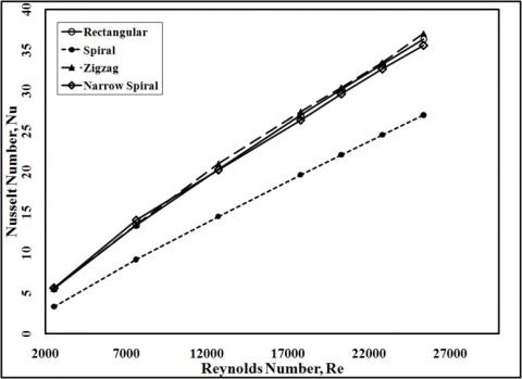
The variations of the Nusselt number with the Reynolds number for the four patterns are illustrated in Figure 16. From the figure, it is observed that the Nusselt number increases with the Reynolds number for all passage patterns. For the same Reynolds number, there are little variations in the Nusselt values for the rectangular, the zigzag, and the narrow-spiral patterns, and a considerable reduction in the Nusselt values for the spiral type. That may be because all the four passage types have the same length but all the passage of the spiral passage has curved walls that keep changing the air momentum vectors directions near the walls along the whole passage. During this process, a large part of the kinetic energy of the flowing air converts into pressure energy and higher air density, which has lower momentum near the wall. This leads to lower rates of air renewal near the walls and accordingly, lower rates of convective heat transfer. Thus, the possibilities of heat exchange with the walls decrease but the conductivities of the wall and the fluid almost do not change, and thus, a reduction in the Nusselt number occurs. This interpreting could be more logical when we observe the increase in Nu values for the rectangular and zigzag passages which contain smaller lengths of curved walls than those of the spiral type. For the narrow-spiral type, although, the water rate is the same as for the other types, the narrower passages lead to higher gradients for the velocity and the temperature in the normal direction of the flow which promotes more heat transfer near the walls. Also, the long passage of the narrow-spiral type allows larger areas of contact between the two fluids. This increase in pressure compensates for part of the pressure losses through the passage.
Figure 8. The pressure distribution along the rectangular passage
Figure 9. The temperature distribution along the rectangular passage
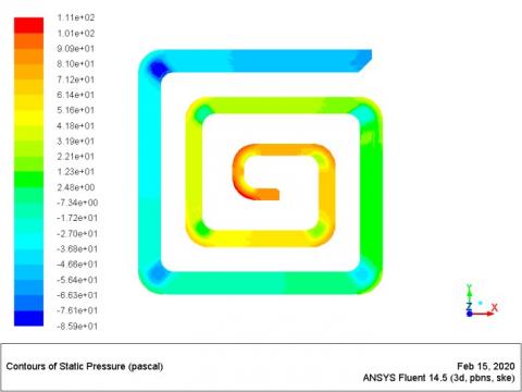
Figure 10. The pressure distribution along the spiral passage
Figure 11. The temperature distribution along the spiral passage
Figure 12. The pressure distribution along the spiral passage
Figure 13. The temperature distribution along the spiral passage
The variations in the non-dimensional pressure loss through the air passage, $\Delta P^{*}$, with the Reynolds number for the four patterns are illustrated in Figure 17. The spiral type exhibits higher values of non-dimensional pressure losses than those of the other three types. That may be because, their curved walls promote more near-wall transverse vortices, which decompose into smaller-scale vortices which in turn, lead to more turbulent shear stresses and more pressure losses near the walls. Although all the walls of the “spiral” and “narrow-spiral” types are curved and have the same lengths, the smaller radii of curvature of the “narrow-spiral” type leads to higher centrifugal forces which are proportional to Uf2/r. A large portion of the kinetic energy is converted into an increase in the pressure energy near the walls due to this increased centrifugal force. The results of the zigzag and rectangular types are close to each other. That may be because they have the same passage lengths, almost the same “straight walls” lengths, and the same number of right angles turns. As mentioned before, the number and angles of turns are the imposing factors affecting the pressure losses.
Figure 14. The pressure distribution along the spiral passage
Figure 15. The temperature distribution along the zigzag passage
The economy of the heat exchanger performance is expressed by the ratio of the two non-dimensional quantities; $N u$ and $\Delta P^{*}$. The variations of this ratio with the Reynolds number for the four patterns are illustrated in Figure 18. From the above discussion, it is clear that, for all Reynolds number values, the narrow-spiral type has the largest values of $N u / \Delta P^{*}$. The experimental simulation for the rectangular type exhibited lower $N u / \Delta P^{*}$ values than those of the prediction. That is because; although the side walls were insulated, they kept transfer unpredicted quantities of heat to the environments. Since this heat leakage could not be predicted exactly, this may lead to decreased measured values of the Nusselt number. Also, the actual inner wall roughness could not be simulated because the welding processes for this complex passage led to little internal corrosion and change in the roughness around the welded edges. So the experimentally measured pressure losses were higher than those of the predictions.
To reduce the time and the effort consumed in any future work, it is more convenient to relate the performance of each one of the four types to the applied Reynolds number. The results suggest formulas to correlate $N u / \Delta P^{*}$ to Re for the four patterns. For a rectangular pattern;
$N u / \Delta P^{*}=-0.594+0.000488 R e-0.000000012 R e^{2}$ (4)
For the spiral pattern;
$N u / \Delta P^{*}=-0.5+0.0003 \mathrm{Re}+0.00000000071 \mathrm{Re}^{2}$ (5)
For zigzag pattern;
$N u / \Delta P^{*}=-0.97+0.0007 \operatorname{Re}-0.0000000086 \operatorname{Re}^{2}$ (6)
For narrow-spiral pattern;
$N u / \Delta P^{*}=-0.97+0.0007 \operatorname{Re}-0.00000000047 R e^{2}$ (7)
Figure 16. The variations of the Nusselt number with the Reynolds number for the four patterns
Figure 17. The variations in the non-dimensional pressure loss, $\Delta P^{*}$, with the Reynolds number
Figure 18. The variation of the ratio of $N u$ and $\Delta P^{*}$ with the Reynolds number for the four patterns
The economic heat exchanger design is investigated based on the maximum value of $N u / \Delta P^{*}$. Four air passage patterns are suggested which are; rectangular, zigzag, spiral, and narrow-spiral patterns. The four air passages have the same cross-section area and passage length. These four patterns are investigated at Reynolds number, Re, of values; 2535, 7606, 12677, 17748, 20284, 22819, 25355. For the validation purpose, the rectangular type was checked experimentally, and the results of $N u / \Delta P^{*}$ were slightly lower than those of the predicted. For all values of the Reynolds number, the suggested narrow-spiral pattern exhibited the highest values of the ratio $N u / \Delta P^{*}$ which means higher heat transfer and lower compressing power, and this makes it the most economic design. At the Reynolds number of 25355, the ratio, $N u / \Delta P^{*}$ for the narrow-spiral pattern could achieve a value of about 15.7. Formulas were suggested to correlate $N u / \Delta P^{*}$ to Re for the four patterns.
Alphabetic
|
A |
area |
m2 |
|
$C p$ |
specific heat of air at constant pressure |
kJ.kg-1.K-1 |
|
$D_{h}$ |
hydraulic diameter |
m |
|
h |
heat transfer coefficient |
J.m-2.K-1 |
|
k |
thermal conductivity |
J.m-1.K-1 |
|
P |
Pressure |
N.m2 |
|
r |
radius of curvature |
m |
|
T |
temperature |
K |
|
Uf |
free stream velocity |
m.s-1 |
|
$\dot{V}$ |
air discharge |
m3.s -1 |
|
Greek symbols |
|
|
|
$\Delta P$ |
pressure loss |
N.m-2 |
|
$\Delta P^{*}$ |
pressure loss coefficient |
|
|
r |
density |
kg.m3 |
|
Subscripts |
|
|
|
a |
air |
|
|
f |
free stream condition |
|
|
h |
hydraulic |
|
|
i |
inlet |
|
|
o |
outlet |
|
|
s |
surface |
|
[1] Hasan, M.I., Hasan, H.M., Abid, G.A. (2014). Study of the axial heat conduction in parallel flow microchannel heat exchanger. Journal of King Saud University-Engineering Sciences, 26(2): 122-131. https://doi.org/10.1016/j.jksues.2012.12.004
[2] Hammadi, S.H. (2020). Integrated solar still with an underground heat exchanger for clean water production. Journal of King Saud University-Engineering Sciences, 32(5): 339-345. https://doi.org/10.1016/j.jksues.2019.04.004
[3] De, D., Pal, T.K., Bandyopadhyay, S. (2017). Helical baffle design in shell and tube type heat exchanger with CFD analysis. International Journal of Heat and Technology, 35(2): 378-383. https://doi.org/110.18280/ijht.350221
[4] Cucumo, M., Ferraro, V., Kaliakatsos, D., Mele, M., Galloro, A., Schimio, R., Le Pera, G. (2016). Thermohydraulic analysis of a shell-and-tube “helical baffles” heat exchanger. International Journal of Heat and Technology, 34(2): S255-S262. http://dx.doi.org/10.18280/ijht.34S210
[5] Belloufi, Y., Brima, A., Zerouali, S., Atmani, R., Aissaoui, F., Rouag, A., Moummi, N. (2017). Numerical and experimental investigation on the transient behavior of an earth air heat exchanger in continuous operation mode. International Journal of Heat and Technology, 35(2): 279-288. https://doi.org/10.18280/ijht.350208
[6] Kailash, O., Choudhary Bishwajeet, N.K., Gajera, U.B., Prajapat, S.B., Karangiya, G.A. (2015). Design and experimental analysis of pipe in pipe heat exchanger. International Journal of Modern Engineering Research (IJMER), 5(3): 42-48.
[7] Jathar, L.D., Patil, K.M., Patil, K.N., Patil, L.A., Patil, M.R. (2016). Study of double pipe heat exchanger using washer inserts to improve heat transfer rate. Journal of Emerging Technologies and Innovative Research, 3(6): 99-106. http://www.jetir.org/papers/JETIR1606018.pdf.
[8] Stephenraj, V., Sathishkumar, M.K. (2018). Design, and analysis of heat exchanger for maximum heat transfer rate (multi-model optimisation technique). International Research Journal of Engineering and Technology (IRJET) 5(1).
[9] Singh, A., Sehgal, S.S. (2013). Thermohydraulic analysis of shell-and-tube heat exchanger with segmental baffles. International Scholarly Research Notices, 2013: 1-5. http://dx.doi.org/10.1155/2013/548676.
[10] Parmar, K., Gora, O., Desai, K., Mehta, N. (2017). A Practical Attempt to Improve Performance of Heat Exchanger. International Journal of Advance Research and Innovative Ideas in Education, 3(1): 1542-1546.
[11] Dubey, V.V.P., Verma, R.R., Verma, P.S., Srivastava, A.K. (2014). Performance analysis of shell & tube type heat exchanger under the effect of varied operating conditions. IOSR Journal of Mechanical and Civil Engineering (IOSR-JMCE), 11(3): 8-17.
[12] Bichkar, P., Dandgaval, O., Dalvi, P., Godase, R., Dey, T. (2018). Study of shell and tube heat exchanger with the effect of types of baffles. Procedia Manufacturing, 20: 195-200. https://doi.org/10.1016/j.promfg.2018.02.028
[13] Mishra, M., Das, P.K., Sarangi, S.K. (2004). Optimum design of crossflow plate-fin heat exchangers through genetic algorithm. International Journal of Heat Exchangers, 5(2): 379-401. http://hdl.handle.net/2080/256
[14] Ramachandran, S., Kalaichelvi, P., Sundaram, S. (2008). Heat transfer studies in a spiral plate heat exchanger for water: Palm oil two phase system. Brazilian Journal of Chemical Engineering, 25(3): 483-490. https://doi.org/10.1590/S0104-66322008000300006
[15] Jia, R., Hu, J. (2014). Analysis of a counter flow parallel-plate heat exchanger. ASEE 2014 Zone I Conference, April 3-5, (2014), University of Bridgeport, Bridgeport, CT, USA.