Wanchao Zhu | Minggang Zheng*
© 2019 IIETA. This article is published by IIETA and is licensed under the CC BY 4.0 license (http://creativecommons.org/licenses/by/4.0/).
OPEN ACCESS
The channel structure of flow field is an important influencing factor of the operation and performance of proton exchange membrane fuel cell (PEMFC). Based on circular bipolar plate, three radial flow fields, namely, Radial-I, Radial-II and Radial-III, with different structures were created, and compared to disclose the effects of radial channel on the flow field for the PEMFC. The results show that radial flow fields clearly outperformed traditional flow fields like parallel, single serpentine and multiple serpentine flow fields. Radial-II has the highest current density and power density than any other flow field. The channel and rib widths of radial flow field have greater impacts on PEMFC performance than channel depth. Radial flow field can effectively improve the water discharge and reduce the pressure drop of the PEMFC. The research findings shed new light on the performance improvement of the PEMFC.
proton exchange membrane fuel cell (PEMFC), radial flow field, bipolar plate, pressure drop
Proton exchange membrane fuel cell (PEMFC) is a power generation device that directly converts hydrogen chemical energy into electrical energy with high current density. The pollution-free device operates under a low temperature, offering an effectively way to alleviate energy and environmental crisis [1, 2]. The performance of the PEMFC is greatly affected by the channel structure of the flow field, which determines the migration of water and the distribution of reaction gas. A reasonable channel structure ensures the even distribution of reaction gas in the reaction zone of the bipolar plate, and eliminates the water generation in time [3, 4]. Therefore, the channel structure should be improved to enhance the power density and reduce the manufacturing cost of the PEMFC.
The relevant studies mainly focus on traditional flow fields, such as the parallel flow field and serpentine flow field. Despite low flow resistance and small pressure loss, the parallel flow field performs poorly in water discharge, which causes water flooding in the channel and unstable cell performance. Many scholars have attempted to optimize the channel structure of parallel flow field. For instance, Chowdhury et al. [5] adopted parameter scanning function to optimize channel and rib widths in 73 parallel flow fields for the PEMFC, concluding that the most suitable channel and rib widths are both 1.0mm. Wang et al. [1] designed a parallel cathode flow field with sub-channel, and explored the impacts of inlet position and flow velocity on channel pressure and battery performance. Compared with the traditional design, the optimized design achieves a reduced voltage drop, a high limit current density and a high maximum power density.
The serpentine flow field enjoys great popularity due to its excellence in water removal. However, this flow field has two main drawbacks: The reactant mass is unevenly distributed along the long channel [6]; Under the high pressure drop, the transport of the reactive gas requires a high pumping power, resulting in a huge parasitic pumping loss [7]. Much research has been done to overcome these defects. For example, Taccani et al. [8] studied the overall performance and pressure drop of 5-serpentine, 4-serpentine and parallel flow fields, revealing that the first structure has the best power density but a large pressure drop. Vazifeshenas et al. [9] conducted a 3D simulation of a composite flow field, which retains the serpentine design and excels it in many aspects. Singdeo et al. [10] proposed a multi-channel serpentine cross flow field, in which the reactant density varies between adjacent channels, and proved that the cross-diffusion improves the uniformity of gas distribution. In fact, multi-channel serpentine channel has been widely adopted thanks to its flexibility and applicability.
In recent years, some new flow fields have emerged, such as intersecting flow field [11], spiral flow field [12], tree-like flow field [13] and radial flow field [14, 15]. In addition, Toyota Mirai [16, 17] developed a 3D complex flow field good at water management and oxygen delivery, but the channel structure is complex, costly and difficult to process.
In this paper, a circular radial flow field is designed, which inherits the discharge capacity of serpentine channel and the flow distribution features of parallel channel. Then, a mathematical model was established for numerical analysis on the discharge capacity and pressure drop of radial flow fields with different structures. The numerical analysis was performed to disclose the behaviors of radial flow field under different conditions without establishing a real model. After all, it is very difficult to optimize the flow field structure of bipolar plate by experimental method [18, 19].
As shown in Figure 1, the computing domain of the PEMFC consists of an anode channel, an anode diffusion layer, an anode catalytic layer, a proton exchange membrane, a cathode catalytic layer, a cathode diffusion layer, and a cathode channel.
The radial flow field was modelled with eight independent yet identical inlets. Each inlet has three 4mm-long longitudinal channels and three 1mm-wide arc-shaped channels. The size of each longitudinal channel is equal to that of the area between longitudinal channels (rib1). Three radial flow fields with different structures, namely, Radial-I, Radial-II and Radial-III, are presented in Figure 2. The effective areas of the three radial flow fields are all 9cm2. Taking the center of the circular bipolar plate as the origin, the radian of each inlet is 39.375°, and that of the area between inlets is 5.625°. The three radial flow fields differ in radian, the number of longitudinal channels and size.
Figure 1. The computing domain of the PEMFC
Figure 2. Three radial flow fields with different structures
2.1 Hypotheses and parameters
A 3D steady-state mathematical model was established under the isothermal condition of a PEMFC. The following hypotheses were put forward for model construction [20, 21]:
(1) The cell operates at the temperature of 80℃.
(2) All gas phases (hydrogen, oxygen and water vapor) are incompressible ideal gases.
(3) The effect of gravity is negligible.
(4) All porous media (proton exchange membrane, catalytic layer and gas diffusion layer) are isotropic and homogeneous.
(5) The gas flow in the cell is a laminar flow.
The main parameters of the PEMFC model are listed in Table 1.
Table 1. The main parameters
|
Parameter |
Value |
|
GDL thickness (m) |
3.80×10⁻⁴ |
|
Porous electrode thickness (m) |
5×10⁻⁵ |
|
Membrane thickness (m) |
1×10⁻⁴ |
|
GDL porosity |
0.4 |
|
GDL permeability (m2) |
1×10-13 |
|
GDL electric conductivity (S/m) |
222 |
|
Inlet H2 mass fraction (anode) |
0.743 |
|
Inlet H2O mass fraction (cathode) |
0.023 |
|
Inlet oxygen mass fraction (cathode) |
0.228 |
|
Anode inlet flow velocity (m/s) |
2 |
|
Cathode inlet flow velocity (m/s) |
2 |
|
Anode viscosity (Pa·s) |
1.19×10⁻⁵ |
|
Cathode viscosity (Pa·s) |
2.46×10⁻⁵ |
|
Hydrogen molar mass (kg/mol) |
0.002 |
|
Nitrogen molar mass (kg/mol) |
0.028 |
|
Water molar mass (kg/mol) |
0.018 |
|
Oxygen molar mass (kg/mol) |
0.032 |
|
H2-H2O Binary diffusion coefficient (m2/s) |
1.1684×10⁻⁴ |
|
N2-H2O Binary diffusion coefficient (m2/s) |
3.2682×10⁻⁵ |
|
O2-N2 binary diffusion coefficient (m2/s) |
3.0466×10⁻⁵ |
|
O2-H2O binary diffusion coefficient (m2/s) |
3.5807×10⁻⁵ |
|
Cell temperature (K) |
353.15 |
|
Reference pressure (Pa) |
1.01×10⁻⁵ |
|
Cell voltage (V) |
0.4 |
|
Oxygen reference concentration (mol/m3) |
40.88 |
|
Hydrogen reference concentration (mol/m3) |
40.88 |
|
Electrolyte phase volume fraction |
0.3 |
|
Open volume fraction for gas diffusion in porous electrodes |
0.3 |
|
Permeability (porous electrode) (m2) |
2×10-14 |
|
Membrane conductivity (S/m) |
9 |
|
Tafel slope, A (mV) |
-95 |
2.2 Governing equations
The PEMFC model mainly invokes the following equations: the mass transfer equation and the equations of conservation of charge, mass, momentum, energy and component. Some other equations were included to tackle special phenomena of fuel cells. For example, the Butler-Volmer equation and cathode Tafel equation were called to describe the current-potential relationship, and the Darcy equation was employed to depict the fluid flows in channels and porous media.
2.2.1 Charge conservation equation
The solid phase transfer current and the membrane ion transfer current can be respectively defined as [22]:
$\nabla \bullet\left(\kappa_{s}^{e f} \nabla \varphi_{s}\right)=S_{\varphi s}$ (1)
$\nabla \bullet\left(\kappa_{m}^{\mathscr{C} f} \nabla \varphi_{m}\right)=S_{\varphi m}$ (2)
where, $\kappa_{s}^{e f f}, \varphi_{s}$ and $S_{\varphi s}$ are the conductivity, potential and the source term of the transfer current of the solid phase, respectively; $\kappa_{m}^{e f f}, \varphi_{m}$ and $S_{\varphi m}$ are the conductivity, potential and the source term of the transfer current of the membrane phase, respectively.
For the solid phase catalytic layer, $S_{\varphi s}=-j_{a}$ on the anode side and $S_{\varphi s}=j_{a}$ on the cathode side. For the catalytic layer of the membrane phase, $S_{\varphi m}=j_{c}$ on the anode side and $S_{\varphi m}=-j_{c}$ on the cathode side. In other areas, $S_{\varphi s}=0$ and $S_{\varphi m}=0$
According to the linear concentration-dependent Butler-Volmer equation, the anode current density can be derived as [23]:
$i_{a}=i_{0, a}\left(\frac{c_{H_{2}}}{c_{H_{2}, r e f}}\right)^{0.5}\left(\frac{\alpha_{a, a}+\alpha_{c, a}}{R T} F \eta_{a}\right)$ (3)
$i_{0, a}=10^{5}\left(\frac{c_{H_{2}}}{c_{H_{2}, r e f}}\right)^{0.5}$ (4)
where, ia and i0,a are the densities of transfer current and anode exchange current, respectively; $c_{H_{2}}$ and $c_{H_{2}, r e f}$ are the local and reference hydrogen concentrations, respectively; $\alpha_{a, a}$ and $\alpha_{c, a}$ are anode and cathode charge transfer constants, respectively; R is the ideal gas constant; T is the operating temperature (K); K is the Faraday constant; $\eta_{a}$ is anode overvoltage.
Meanwhile, the cathode current density can be derived from the cathode Tafel equation:
$i_{c}=-i_{0, c}\left(\frac{c_{O_{2}}}{c_{O_{2}, r e f}}\right) 10^{\eta_{c} / A_{C}}$ (5)
$i_{0, c}=\left(\frac{c_{O_{2}}}{c_{O_{2}, r e f}}\right)$ (6)
where, $i_{c}$ and $i_{0, c}$ are the densities of transfer current and cathode exchange current, respectively; $c_{O_{2}}$ and $c_{O_{2}, r e f}$ are the local and reference oxygen concentrations, respectively; $A_{c}$ is the slope of Tafel; $\eta_{c}$ is the cathode overpotential.
2.2.2 Mass conservation equation
In the PEMFC, the general mass conservation of fluid flow, diffusion, phase change and electrochemical reaction can be expressed as:
$\frac{\partial \rho}{\partial t}+\nabla \bullet(\rho v)=S_{m}$ (7)
where, $\rho$ and $v$ are the density and velocity vectors of the fluid, respectively; $S_{m}$ is the mass source term, which differs from area to area.
On the anode catalytic layer:
$S_{m}=S_{H_{2}}=-\frac{M_{H_{2}}}{2 F} i_{a}$ (8)
On the cathode catalytic layer:
$S_{m}=m_{O_{2}}+m_{H_{2} O_{c}}=\frac{M_{H_{2} O}}{2 F} i_{c}-\frac{M_{O_{2}}}{4 F} i_{c}$ (9)
In other areas:
$S_{m}=0$ (10)
where, $M_{H_{2}}, M_{O_{2}}$ and $M_{H_{2} O}$ are molar mass fractions of hydrogen, oxygen and water, respectively.
2.2.3 Momentum conservation equation
The conservation of momentum in the PEMFC can be described as [24]:
$\left[\frac{\partial(\rho v)}{\partial t}\right]+\nabla \bullet(\rho v v)=-\nabla p+\nabla \bullet(\mu \nabla v)+S_{m}$ (11)
where, P is the fluid pressure; $\mu$ is the dynamic viscosity of the fluid; Sm is the momentum source term, which also differs from area to area.
In the gas channel:
$S_{m}=0$ (12)
In the porous medium:
$S_{m}=-\frac{\beta}{\mu} \nabla P$ (13)
where, $\beta$ is the permeability coefficient of porous media diffusion layer.
2.2.4 Energy conservation equation
In the PEMFC, the external energy per unit time equals the total internal energy generated in the period. The internal energies include ohmic heat $S_{o},$ chemical reaction heat $S_{r e a},$ the phase change heat of water $S_{l q}$ and overpotential heat $S_{\eta}$. The conservation of energy can be described as:
$\frac{\partial\left(\rho c_{p} T\right)}{\partial t}+\nabla \bullet\left(\rho c_{p} v T\right)=\nabla \bullet\left(k_{e f f} \nabla T\right)+S_{T}$ (14)
where, $c_{p}$ is the specific heat of fuel gas at constant pressure; $T$ is the operating temperature; $k_{e f f}$ is the effective thermal conductivity; $S_{T}$ is the energy source term. The $S_{T}$ value can be computed by:
$S_{T}=S_{o}+S_{r e a}+S_{\mathrm{lg}}+S_{\eta}$
$=I^{2} R_{o b m}+\alpha S_{H_{2} O} H_{r e a}+R_{w} H_{\mathrm{lg}}+S_{a, c} \eta$ (15)
where, $I$ is the area current density; $R_{\text {ohm}}$ is ohmic resistivity; $\alpha$ is energy conversion efficiency; $S_{H_{2} O}$ is the formation rate of water vapor; $H_{\text {rea}}$ is reaction enthalpy; $R_{w}$ is phase transition rate of water; $H_{l g}$ is phase change enthalpy of water; $S_{a, c}$ is exchange current density of anode and cathode; $\eta$ is overpotential.
2.2.5 Component conservation equation
The mass conservation equation cannot illustrate the mass change of all substances in areas, where new substances are produced through complex electrochemical reactions. In this case, the mass change can be described by the component conservation equation:
$\frac{\partial c_{k}}{\partial t}+\nabla \bullet\left(v c_{k}\right)=\nabla \bullet\left(D_{k}^{e f f} \nabla c_{k}\right)+S_{k}$ (16)
where, Ck is the component concentration; $D_{k}^{e f f}$ is the effective diffusion coefficient of the component; is the component source term. On the anode side, the substances include hydrogen and water vapor; on the cathode side, the substances include oxygen, nitrogen and water vapor.
On the catalyst layer, the Sk values of hydrogen, oxygen and water vapor are respectively:
$S_{H_{2}}=-\frac{1}{2 F} i_{a}$ (17)
$S_{o_{2}}=-\frac{1}{4 F} i_{c}$ (18)
$S_{H_{2} O}=\frac{1}{2 F} i_{c}$ (19)
In the flow field and diffusion layer, the Sk value can be expressed as:
$S_{k}=0$ (20)
2.2.6 Mass transfer equation
The mass transfer of the PEMFC mainly involves the hydrogen on the anode side, and the oxygen and water on the cathode side. The mass transfer equations are as follows:
$\frac{\partial c_{H_{2}}}{\partial t}+\nabla \bullet\left(v c_{H_{2}}\right)=\nabla \bullet\left(D_{H_{2}}^{e f f} \nabla c_{H_{2}}\right)+S_{H_{2}}$ (21)
$\frac{\partial c_{O_{2}}}{\partial t}+\nabla \bullet\left(v c_{O_{2}}\right)=\nabla \bullet\left(D_{O_{2}}^{e f f} \nabla c_{O_{2}}\right)+S_{O_{2}}$ (22)
$\frac{\partial c_{H_{2} O}}{\partial t}+\nabla \bullet\left(v c_{H_{2} O}\right)=\nabla \bullet\left(D_{H_{2} o}^{e f f} \nabla c_{H_{2} O}\right)+S_{H_{2} O}$ (23)
where, $c_{k}$ represents the mass fraction of substance $k$ (hydrogen, oxygen or water); $D_{k}^{\text {eff }}$ is the effective diffusion coefficient of substance $k ; M_{k}$ is the molar mass of substance $k ; S_{k}$ is the source term of substance $k .$
On the catalyst layer, the Sk values of hydrogen, oxygen and water vapor are respectively [23]:
$S_{H_{2}}=-\frac{M_{H_{2}}}{2 F} i_{a}$ (24)
$S_{O_{2}}=-\frac{M_{O_{2}}}{4 F} i_{c}$ (25)
$S_{O_{2}}=-\frac{M_{O_{2}}}{4 F} i_{c}$ (26)
In the flow field and diffusion layer, the Sk value can be expressed as:
$S_{k}=0$ (27)
3.1 Initial and boundary conditions
Our numerical simulation was carried out under the following initial and boundary conditions [25]:
(1) The internal boundaries are continuous in all domains.
(2) There is no slip condition.
(3) The gas diffusion layer and catalyst layers have symmetric boundaries.
(4) The reference pressure is 101kPa.
(5) The inlet flow rates are constant on the anode and cathode sides.
(6) The electrolyte potential is initialized as zero for the anode side and as open circuit potential for the cathode side.
3.2 Meshing and grid independence
Radial-I was taken as the example to explain the mesh structure of the three flow fields. As shown in Figure 3(a), Radial-I was meshed into 346,000 grids. The grid independence was tested six times by reducing and increasing the number of grids by 14~20%. The results in Figure 3(b) show that the number of grids has no impact on the PEMFC performance.
Figure 3. Mesh structure and grid independence test of Radial-I
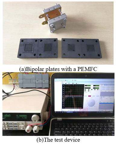
3.3 Test conditions
Under the specified conditions and parameters, our mathematical model was firstly verified using parallel and 5-serpentine channels. The PEMFC was installed on two bipolar plates (Figure 4(a)), and its performance was tested on ITECH’s IT8700 series programmable DC electronic loads (Figure 4(b)). The voltage range was set to 0.2~0.9V and the step size to 0.05V for discharge. The test results were recorded by a computer.
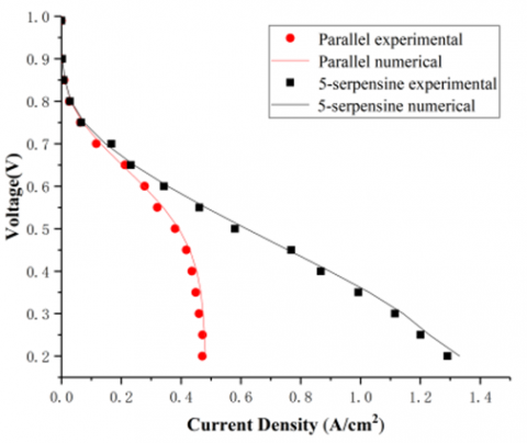
The polarization curves of parallel and 5-serpentine channel structures were obtained under the same conditions and parameters (Figure 5). Obviously, the error between the simulated and experimental curves was less than 1%, which proves the reliability of our model.
Figure 4. The test setup
Figure 5. Comparison between simulated and experimental polarization curves
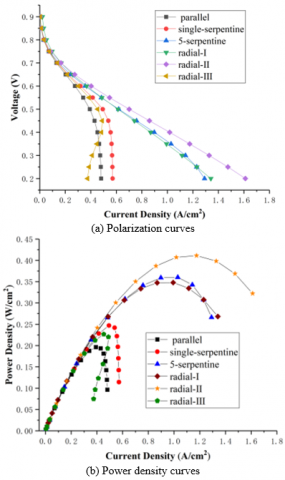
4.1 Polarization curves
In the PEMFC, the voltage loss mainly occurs in activation polarization, ohmic polarization and concentration polarization [26, 27]. Figure 6 presents the polarization and power density curves of Radial-Ⅰ, Radial-Ⅱ, Radial-Ⅲ, parallel, single serpentine and 5-serpentine flow fields. Obviously, the radial flow fields were similar to the traditional flow fields in the activation polarization region (low current density), but differed greatly from the latter in the ohmic polarization region and concentration polarization region (high current density). Radial-I and Radial-II had higher limit current density and power density than the flow fields with other channel structures. The advantage of Radial-II was particularly obvious. Moreover, the 5-serpentine flow field had a similar curve between power density and current density as Radial-I, which is lower than that of Radial-II. In addition, Radial-I, Radial-II and Radial-III reached the peak power density at the working voltage of 0.4V. Thus, this voltage was set as the working voltage of radial flow fields.
Figure 6. Comparison of flow fields with different structures
4.2 Effects of flow field structure
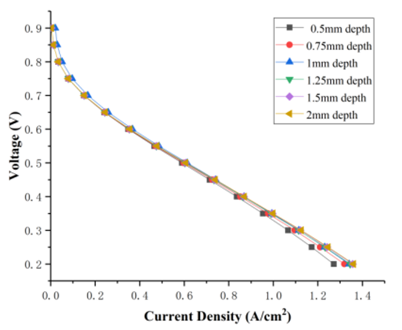
This subsection analyzes the effects of channel depth, channel width and rib width on the performance of radial flow fields. Taking the Radial-I as an example, the PEMFC performances were measured at the channel depths of 0.5 mm, 0.75 mm, 1 mm, 1.25 mm, 1.5mm and 2mm (Figure 7). It can be seen that the polarization curves of Radial-I were almost the same at different channel depths. This means the channel depth has little effect on the performance of radial flow fields
Water discharge is a thorny issue in the design of channel structure [28]. The water produced at the cathode catalysis layer is normally collected in the diffusion layer and discharged through the channel. If not discharged in time, the water will block the cathode channel, hinder the mass transfer of oxygen, and affect the PEMFC performance [29].
Figure 7. Polarization curves of Radial-I at different channel depths
With the channel depth of 1mm, the effects of channel and rib widths on the performance of the radial flow field was analyzed based on the water content distribution in the cathode channel of Radial-I, Radial-II and Radial-III. As shown in Figure 8, Radial-I and Radial-II had lower but more uniformly distributed water content than Radial-III, and the water content in Radial-III increased gradually from 1.05mol/m3 at the inlet to 11.9mol/m3 near the outlet. This is attributable to the following facts: as the reaction proceeds, the generated water gradually accumulates, pushing up the water content along the direction of the gas flow. Compared with Radial-Ⅰ and Radial-Ⅱ, Radial-Ⅲ is very likely to face flooding, which affects the transport of cathode gas.
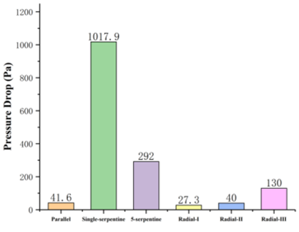
The channel with a high pressure drop needs a huge pumping power to transport reactive gas. This inevitably brings a great parasitic energy loss and reduces cell efficiency. Therefore, the pressure drop is another consideration in channel design.
Figure 9 compares the pressure drop in cathodic channel between Radial-I, Radial-II, Radial-III, parallel, single serpentine and 5-channel serpentine flow fields. It can be seen that the pressure drops of parallel, single serpentine and 5 serpentine flow fields were 41.6Pa, 1,017.9Pa and 292Pa, respectively. The pressure drops of Radial-I, Radial-II and Radial-III were 27.3Pa, 40Pa and 130Pa, respectively. The numerical results show the significant correlation between pressure drop with channel structure. In general, Radial-I and Radial-II had equal or smaller pressure drops than the parallel flow field, and lagged Radial-III in pressure drop. The relatively high pressure drop in Radial-III is resulted from the suppression effect of reaction generated water over oxygen transport. Hence, Radial-I and Radial-II are more rational than Radial-III in channel structure.
Since the flow of the reaction medium is constant, the channel flow velocity normally has a negative correlation with the cross-section area of the flow passage, and the mass of the reaction medium on the catalyst layer tends to increase with time. Therefore, the smaller the cross-section area of the flow passage, the stronger the current density and power density.
However, Radial-III has an extremely small limit current density and maximum power density, although it has a smaller cross-sectional area than Radial-I and Radial-II. The possible reason is that the cross-section area of Radial-III is too small. The channel is easily blocked by water, making it difficult to transport oxygen. This further confirms the importance of channel and rib widths to PEMFC performance and in channel design.
Figure 8. Water content distribution in cathode channel
Figure 9. Pressure drops of flow fields with different channel structures
The radial flow fields were compared with traditional flow fields in terms of polarization curves and pressure drop. The comparison shows that the radial flow fields with reasonable structure has the higher limit current density and maximum power density. Among the traditional flow fields, the 5-serpentine flow field has very high limit current density and maximum power density. However, the pressure drop of this flow field is much larger than that of the radial flow fields. The large pressure drop requires a huge pumping power to transport reactive gas, which induces a very large parasitic energy loss.
The channels of Radial-I, Radial-II and Radial-III were contrasted in water content distribution, pressure drop and polarization curves. The results show that the channel depth has a negligible impact on the performance of radial flow fields, while the channel and rib widths directly affect the performance of radial flow fields. Radial-II enjoys the best limit current density and maximum power density among all channel designs, and Radial-Ⅲ has equal or even lower limit current density and maximum power density than the parallel flow field. This fully demonstrates the importance of channel structure to radial flow fields. Among the three radial flow fields, Radial-II has the best channel structure, which provides an acceptable current density, a low pressure drop and a compact flow field to the PEMFC. Our research shows the broad prospects of radial flow field in the PEMFC.
This work was supported by major scientific and technological innovation projects in Shandong province (No. 2018CXGC0803).
[1] Wang, Y., Yue, L., Wang, S. (2017). New design of a cathode flow-field with a sub-channel to improve the polymer electrolyte membrane fuel cell performance. Journal of Power Sources, 344: 32-38. https://doi.org/10.1016/j.jpowsour.2017.01.075
[2] Deluga, G.A., Salge, J.R., Schmidt, L.D., Verykios, X.E. (2004). Renewable hydrogen from ethanol by autothermal reforming. Science, 303(5660): 993-997. https://doi.org/10.1126/science.1093045
[3] Shen, X., Tan, J.Z., Li, Y. (2017). Numerical study on the influence of cathode flow channel baffles on PEM fuel cell performance. Applied Mechanics and Materials, 853: 410-415. https://doi.org/10.4028/www.scientific.net/AMM.853.410
[4] Ferng, Y.M., Su, A. (2007). A three-dimensional full-cell CFD model used to investigate the effects of different flow channel designs on PEMFC performance. International Journal of Hydrogen Energy, 32(17): 4466-4476. https://doi.org/10.1016/j.ijhydene.2007.05.012
[5] Chowdhury, M.Z., Genc, O., Toros, S. (2018). Numerical optimization of channel to land width ratio for PEM fuel cell. International Journal of Hydrogen Energy, 43(23): 10798-10809. https://doi.org/10.1016/j.ijhydene.2017.12.149
[6] Shimpalee, S., Greenway, S., Zee, J.W.V. (2006). The impact of channel path length on PEMFC flow-field design. Journal of Power Sources, 160(1): 398-406. https://doi.org/10.1016/j.jpowsour.2006.01.099
[7] Bachman, J., Charvet, M., Santamaria, A., Tang, H.Y., Park, J.W., Walker, R. (2012). Experimental investigation of the effect of channel length on performance and water accumulation in a PEMFC parallel flow field. International Journal of Hydrogen Energy, 37(22): 17172-17179. https://doi.org/10.1016/j.ijhydene.2012.08.023
[8] Taccani, R., Zuliani, N. (2011). Effect of flow field design on performances of high temperature PEM fuel cells: Experimental analysis. International Journal of Hydrogen Energy, 36(16): 10282-10287. https://doi.org/10.1016/j.ijhydene.2010.10.026
[9] Vazifeshenas, Y., Sedighi, K., Shakeri, M. (2015). Numerical investigation of a novel compound flow-field for PEMFC performance improvement. International Journal of Hydrogen Energy, 40(43): 15032-15039. https://doi.org/10.1016/j.ijhydene.2015.08.077
[10] Singdeo, D., Dey, T., Gaikwad, S., Andreasen, S.J., Ghosh, P.C. (2017). A new modified-serpentine flow field for application in high temperature polymer electrolyte fuel cell. Applied Energy, 195: 13-22. https://doi.org/10.1016/j.apenergy.2017.03.022
[11] Wen, D.H., Yin, L.Z., Piao, Z.Y., Lu, C.D., Li, G., Leng, Q. (2018). Performance investigation of proton exchange membrane fuel cell with intersectant flow field. International Journal of Heat and Mass Transfer, 121: 775-787. https://doi.org/10.1016/j.ijheatmasstransfer.2018.01.053
[12] Ibrahimoglu, B., Yilmazoglu, M.Z., Celenk, S. (2018). Investigation of spiral flow-field design on the performance of a PEM fuel cell. Fuel Cells, 17(6): 786-793. https://doi.org/10.1002/fuce.201700076
[13] Chen, T., Xiao, Y., Chen, T. (2012). The impact on PEMFC of bionic flow field with a different branch. Energy Procedia, 28: 134-139. https://doi.org/10.1016/j.egypro.2012.08.047
[14] Cano-Andrade, S., Hernandez-Guerrero, A., Spakovsky, M.R.V., Damian-Ascencio, C.E., Rubio-Arana, J.C. (2010). Current density and polarization curves for radial flow field patterns applied to PEMFCs (Proton Exchange Membrane Fuel Cells). Energy, 35(2): 920-927. https://doi.org/10.1016/j.energy.2009.07.045
[15] Friess, B.R., Hoorfar, M. (2012). Development of a novel radial cathode flow field for PEMFC. International Journal of Hydrogen Energy, 37(9): 7719-7729. https://doi.org/10.1016/j.ijhydene.2012.02.012
[16] Li, W., Zhang, Q., Wang, C., Yan X. (2017). Experimental and numerical analysis of a three-dimensional flow field for PEMFCs. Applied Energy, 195: 278-288. https://doi.org/10.1016/j.apenergy.2017.03.008
[17] Kim, J., Luo, G., Wang, C.Y. (2017). Modeling two-phase flow in three-dimensional complex flow-fields of proton exchange membrane fuel cells. Journal of Power Sources, 365: 419-429. https://doi.org/10.1016/j.jpowsour.2017.09.003
[18] Qin, Y., Liu, G., Chang, Y., Du, Q. (2018). Modeling and design of PEM fuel cell stack based on a flflow network method. Applied Thermal Engineering, 144: 411-423. https://doi.org/10.1016/j.applthermaleng.2018.08.050
[19] Sainan, K.I., Atan, R., Husain, H., Mohamed, W.A.N.W. (2011). Computational model analysis on a bipolar plate flow field design of a PEM fuel cell. 2011 5th International Power Engineering and Optimization Conference. https://doi.org/10.1109/PEOCO.2011.5970420
[20] Ramiar, A., Mahmoudi, A.H., Esmaili, Q., Abdollahzadeh, M. (2016). Influence of cathode flow pulsation on performance of proton exchange membrane fuel cell with interdigitated gas distributors. Energy, 94: 206-217. https://doi.org/10.1016/j.energy.2015.10.110
[21] Sezgin, B., Caglayan, D.G., Devrim, Y., Steenberg, T., Eroglu, I. (2016). Modeling and sensitivity analysis of high temperature PEM fuel cells by using Comsol Multiphysics. International Journal of Hydrogen Energy, 41(23): 10001-10009. https://doi.org/10.1016/j.ijhydene.2016.03.142
[22] Chowdhury, M.Z., Timurkutluk, B. (2018). Transport phenomena of convergent and divergent serpentine flow fields for PEMFC. Energy, 161(C): 104-117. https://doi.org/10.1016/j.energy.2018.07.143
[23] Wu, H.W. (2016). A review of recent development: Transport and performance modeling of PEM fuel cells. Applied Energy, 165: 81-106. https://doi.org/10.1016/j.apenergy.2015.12.075
[24] Zamel, N., Li, X. (2010). Non-isothermal multi-phase modeling of PEM fuel cell cathode. International Journal of Energy Research, 34(7): 568-584. https://doi.org/10.1002/er.1572
[25] Xing, L., Du, S., Chen, R., Mamlouk, M., Scott, K. (2016). Anode partial flooding modelling of proton exchange membrane fuel cells: Model development and validation. Energy, 96: 80-95. https://doi.org/10.1016/j.energy.2015.12.048
[26] Chan, D.S., Dai, D.J., Wu, H.S. (2012). Dynamic modeling of anode function in enzyme-based biofuel cells using high mediator concentration. Energies, 5(12): 2524-2544. https://doi.org/10.3390/en5072524
[27] Min, C., He, J., Wang, K., Xie, L., Yang, X. (2019). A comprehensive analysis of secondary flow effects on the performance of PEMFCs with modified serpentine flow fields. Energy Conversion and Management, 180: 1217-1224. https://doi.org/10.1016/j.enconman.2018.11.059
[28] Chen, Z.X., Ingham, D.B., Ismail, M.S., Ma, L., Hughes, K.J., Pourkashanian, M. (2018). Dynamics of liquid water in the anode flow channels of PEM fuel cells: A numerical parametric study. Journal of the Energy Institute. https://doi.org/10.1016/j.joei.2018.10.016
[29] Bozorgnezhad, A., Shams, M., Kanani, H., Hasheminasab, M., Ahmadi, G. (2015). The experimental study of water management in the cathode channel of single-serpentine transparent proton exchange membrane fuel cell by direct visualization. International Journal of Hydrogen Energy, 40(6): 2808-2832. https://doi.org/10.1016/j.ijhydene.2014.12.083