OPEN ACCESS
In the present work, the law of motion of reflectors for a concentrating solar Linear Fresnel plant is geometrically analyzed. Firstly, a method for optimally distributing the primary reflectors on the ground is proposed. Furthermore, the mathematical procedure used to identify the law of motion that the mirrors must follow to reflect solar radiation on the absorber tube is presented. To make better use of the surface area occupied by the plant it is necessary to distance the rows of mirrors adequately so that the effects of shading and blocking between the same can be reduced. Avoiding these phenomena allows the initial costs of the plant to be reduced since the reflective material is not used in excess, thus allowing exploitation of the entire reflective surface available. In the work, using spherical trigonometry concepts, the motion law equation of the mirrors is detected. It allows the angle that they must assume in every moment of the day to be established and it has an entirely general valence: it can be applied to each plant according to its constructional characteristics and to each type of orientation. Finally, a comparison is carried out in which the main tracking differences between the plants oriented North-South and East-West are analyzed.
concentrating solar power, linear fresnel, law of motion, primary reflectors
Concentrated solar systems are a solution to obtain thermal or electric energy using the solar source and, therefore, they allow to reduce the air pollution [1]. A linear plant with Fresnel Reflectors is made up of some rows of flat mirrors that reflect direct solar radiation on a fixed receiver. The latter is placed at a few meters from the ground parallel to the rows of mirrors. It consists of an absorber tube, inside which the heat transfer fluid flows. It transports the absorbed energy in order to be used for the production of thermal energy, electric energy or in cogeneration, replacing plants which use non-renewable sources [2]. The plant, in addition, can be provided with a thermal storage tank, necessary to supply the moments of little or no solar radiation. The working fluid can be diathermic oil, a mixture of molten salts or water for the direct production of steam [3]. Above the absorber tube, usually, a secondary reflector or a hot chamber is used to retain solar radiation [4]. The primary reflectors are provided with one degree of freedom: the rotation around the axis parallel to the tube receiver. The use of only plane mirrors reduces costs with respect to the production and use of more complex geometries. In addition, using more mirrors means it approaches the case of a parabolic reflector.
This work provides a method to determine the optimal spacing of the reflectors in order to avoid shading phenomena. Later, the mathematical law useful to know the position that each reflector must assume in every hour of the day is obtained.
Linear Fresnel reflectors have some advantages compared to a parabolic trough power plant. In addition to reduced installation costs, a feature that distinguishes them is the better use of the land. In fact, a small gap between the mirrors is sufficient to minimize shading.
The main energy losses due to the arrangement of the primary reflectors are analyzed. An important cause of error is the shading that a primary reflector casts on the reflector in front or behind, according to the time of day. In fact, in this case a small part of a primary reflector is unable to capture rays from the Sun because shaded by another reflector. This leads to a waste of material because the mirror part in the shade does not send any reflection on the absorber tube.
In the case in which the shading phenomenon is not present, another malfunction that should be avoided is due to the blocking phenomenon. In some moments of the day some primary reflectors may reflect solar radiation on the reflector in front or behind. The geometrical losses described are summarized in Figure 1.
Figure 1. Cosine effect, shading and blocking.
The problems mentioned above could be solved by increasing the gap between two rows of primary reflectors, with an increase in the area occupied for the whole plant. Losses due to the cosine effect are inevitable, because the surface of each mirror lies on a different plane from the one perpendicular to solar rays otherwise it would not be possible to reflect solar radiation on the absorption system.
As regards the effects of shading and blocking, instead, it is possible to optimize the amount of material employed by spacing the mirror rows in a suitable manner. In particular, the greater the distance between mirrors the lower the effects of shading and blocking, resulting, however, in an increase in the total surface occupied by the implant (the comparison is made with the same mirror surface). The optimum spacing derives from economic aspects; in fact, with the same available area for the installation of the entire system, in relation to the arrangement of rows, it happens that:
• spacing them slightly, all the radiation incident on the area occupied by the plant is exploited, but a large part of the reflecting surfaces may be in shadow and therefore unused;
• spacing them more, a part of the solar radiation passes through the gap present between the reflectors without producing useful effects; however, the initial costs of the system are reduced because less reflective material is used.
Therefore, the highest producibility is achieved with zero spacing between the reflectors, however, with larger gaps it is possible to reduce initial investment costs at the expense of a slight reduction in producibility.
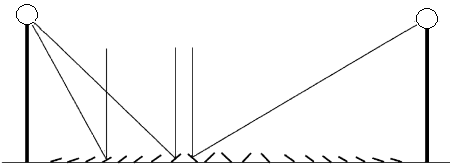
Figure 2. Blocking effect between two adjacent reflectors.
It would be desirable that in the middle of the day, when solar radiation is maximum, all sun rays incident in the area occupied by the plant could be reflected on the absorber tube. This is not possible or it would be, at the limit, if the width of the reflectors were infinitely small. Because of the blocking effects between adjacent rows, in the case where the reflectors had no distance between them, some rays would impact the rear of the previous mirror as shown in Figure 2. It is therefore advantageous to separate them in such a way that at noon this phenomenon will not occur for any row. Because of this arrangement, as mentioned before, a part of the solar radiation penetrates inside the gap, however, it does not produce useful effects as there would be when reflected on another reflector.
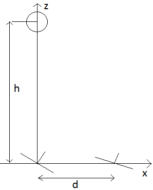
In Figure 2 there are two lines of mirrors: the first is placed at a distance d from the receiver tube and the second at a distance d + z. The mirrors have width L and the tube is placed at a height h from the plane on which the reflectors are fixed. Radiation incident at point B does not reach the tube because it is intercepted by the previous row.
The aim is to determine the distance z, between two rows of mirrors, necessary in order to avoid blocking phenomena.
At point O, the angle formed between the incident and reflected rays, colored in yellow in Figure 2, is the arctangent of d/h; similarly, at the point O’, the same angle can be evaluated through the arctangent of [(d+z)/h]. To evaluate the inclination that the two reflectors take, the law of reflection is used, whereby the angle between the incident ray and that normal to the mirror surface must be congruent to the angle between the normal and the reflected ray. So the normal directions to the two mirrors are determined by the angles:
$\xi=\frac{1}{2} \arctan \frac{\mathrm{d}}{\mathrm{h}}$ (1)
$\xi^{\prime}=\frac{1}{2} \arctan \frac{d+z}{h}$ (2)
Therefore, the coordinates of the points T, A and B are:
T: $x_{T}=0$; $y_{T}=h$; (3)
A: $x_{A}=d+\frac{L}{2} \cos \theta$; $y_{A}=\frac{L}{2} \sin \theta$; (4)
B: $x_{B}=d+x-\frac{L}{2} \cos \theta^{\prime}$; $y_{B}=-\frac{L}{2} \sin \theta^{\prime}$; (5)
Using the figure, it is possible to note that the limit condition, so that there is no effect of blocking, is that these 3 points are aligned with each other, then there must be the following relationship:
$\frac{x_{A}-x_{T}}{x_{B}-x_{T}}=\frac{y_{A}-y_{T}}{y_{B}-y_{T}}$ (6)
so:
$\frac{d+\frac{L}{2} \cos \left(\frac{1}{2} \arctan \frac{d}{h}\right)}{d+x-\frac{L}{2} \cos \left(\frac{1}{2} \arctan \frac{d+x}{h}\right)}=\frac{\frac{L}{2} \sin \left(\frac{1}{2} \arctan \frac{d}{h}\right)-h}{-\frac{L}{2} \sin \left(\frac{1}{2} \arctan \frac{d+x}{h}\right)-h}$ (7)
Eq(7) can be used to obtain the optimal distribution of the rows of mirrors in order to not use surplus material, to be able to reduce the cost and the weight of the structure. Therefore, two reflectors must be spaced by z(d,L,h). The equation is solved by using Matlab software and the results are presented below.
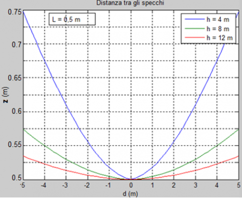
The graph in Figure 3 shows the trend of z as a function of the distance from the center of the system for different values of the height h of the receiver tube.
Figure 3. Distance z between two rows as a function of distance from the receiver tube, for different heights h
In Figure 3 the gap present between the rows increases with the distance from the tube: in fact, the greatest shading and blocking occur for the most external rows. Moreover, for the further pipe heights, the reflectors can be installed closer to each other. By way of example, for a row placed at 4 meters away from the receiver tube, which is positioned 4 meters high, it is (following the blue curve):
$\mathrm{z}=0.675 \mathrm{m}$;
In percentage terms, the vacuum present is:
$\frac{\mathrm{z}-\mathrm{L}}{\mathrm{L}} \approx 0.35=35 \%$.
With the same procedure, it is possible to detect from the graph the position of the next reflector and so on for all rows.
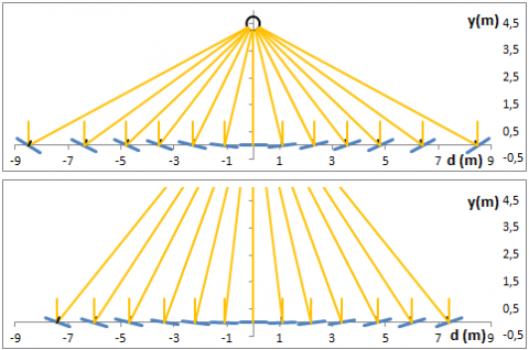
With the increase of plant height h, mirrors can be placed closer and the occupied land is fully exploited; in contrast, the too high absorber requires a very precise solar tracking system and high tolerances on the construction of the reflective panels. Figure 4 shows the arrangement of the mirrors in the case of a tube height of 4.5 m and 9 m.
Figure 4. Position of the mirrors in relation to the tube height
To exploit the entire surface, it is possible to adopt the solution presented in Figure 5: Arranging two plants in parallel in such a way as to overlap the external reflectors by inserting the mirrors of a plant in correspondence to the voids of the other.
This solution can be applied if there is a sufficient distance between two mirrors of the first module to insert a row of mirrors of the other module. In particular, the ratio $\frac{z-L}{L}$ must reach the value of 1 for some rows.
Figure 5. Parallel arrangement of two Linear Fresnel Collectors with intersection of the reflection systems
Each row of mirrors must be inclined relative to the ground in such a way that the reflected beam is always incident on the receiver tube. Therefore, first of all, it is necessary to know the apparent motion of the sun in places of interest. The position of the Sun in the sky is determined using the solar altitude ‘α’ and azimuth ‘a’ calculated with the formulas available in the literature [5].
3.1 Determination of the inclinations of the reflectors
Spherical trigonometry is a branch of spherical geometry that deals with the relationship between sides and angles of spherical polygons, in particular spherical triangles.
In order to solve a geometrical problem on a sphere, the figures should be divided into elementary structures whose relationships are known. The elementary figures identified are spherical triangles.
Figure 6. Spherical triangle
With reference to Figure 6, indicating with $\hat{\mathrm{p}}, \hat{\mathrm{q}}, \hat{\mathrm{r}}$the interior angles and with p, q, r the sides of generic spherical triangle, these equations are valid:
$\cos r=\cos p \cos q+\sin p \sin q \cos \hat{r}$ (8)
$\frac{\sin \mathrm{p}}{\sin \hat{\mathrm{p}}}=\frac{\sin \mathrm{q}}{\sin \hat{\mathrm{q}}}=\frac{\sin \mathrm{r}}{\sin \hat{\mathrm{r}}}$ (9)
For a linear Fresnel plant, the law of motion is first obtained for the reflector below the receiver tube. Later, the law will be modified to extend its validity to other ones.
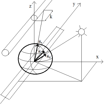
In Figure 7 the three versors characteristic of the reflection are presented [6]. They, having unitary modulus, can be inscribed within a sphere with unit radius:
- versor $\hat{\mathrm{n}}$ is normal to the mirror surface; it belongs to the x-z plan since the mirror can only rotate around the y axis. The objective is to determine the angle that it forms with the horizontal plan;
- versor $\hat{\mathrm{n}}_{\mathrm{t}}$ indicates the direction of the reflected beam; its component along x is nothing because the mirror considered is the one under the receiver tube;
- versor $\hat{\mathrm{n}}_{\mathrm{S}}$ indicates the direction from which sun rays come; it is identified with the solar altitude and azimuth corresponding to the day and time considered.
Figure 7. Versors of reflection within the sphere
The laws of reflection provide two links between the unit vectors:
• the three versors are in the same plan. It means that they must be aligned on a great circle of the sphere;
• the great circle formed between $\hat{\mathrm{n}}$ and $\hat{\mathrm{n}}_{\mathrm{t}}$and one formed between $\hat{\mathrm{n}}$ e $\hat{\mathrm{n}}_{\mathrm{s}}$ are congruent.
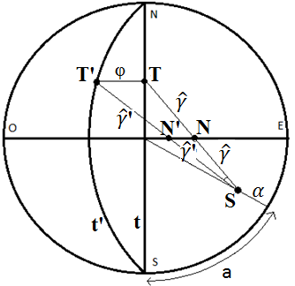
In Figure 8 there is a top view representation of the sphere. On this surface, the points S, N, T are identified. They are given by the intersection respectively with the unit vector of the solar rays, with the unit vector normal to the surface of the reflector, and with the unit vector of the reflected beam.
Figure 8. Top view representation of the sphere
Point S is uniquely determined by the angles α and a (in this case it refers to a general location of the Sun). For the first law of reflection, as already said, the points S, N and T must be in the same great circle. This affirmation is taken into account, in Figure 8, by imposing the equality of the vertex angles $\delta$ in the point N. The second law of reflection is considered by imposing the equality between the arcs of great circle $\hat{\gamma}$ formed between N and T and between N and S. In order to solve the problem some arches are traced to generate spherical triangles. In particular, point A is identified, belonging to the vertical East-West plane and with an angular altitude to the horizontal direction East equal to α. The arc of great circle that connects S with A is indicated with $\widehat{b}$ and it is calculated using Eq(8) applied to the spherical triangle AOS:
$\cos \hat{b}=\cos (90-\alpha) \cos (90-\alpha)+\sin (90-\alpha) \sin (90-\alpha) \cos (90-a)$ (10)
$\cos \hat{b}=\sin ^{2} \alpha+\cos ^{2} \alpha \sin a$ (11)
Applying the Eq(9) to the triangle NOT:
$\frac{\sin \hat{\mathrm{k}}}{\sin \delta}=\frac{\sin \hat{\gamma}}{\sin 90^{\circ}}$ (12)
$\sin \hat{\mathrm{k}}=\sin \hat{\gamma} \sin \delta$ (13)
Applying the Eq(9) also to the triangle ASN:
$\frac{\sin \theta}{\sin \hat{\gamma}}=\frac{\sin \delta}{\sin \hat{b}}$ (14)
$\sin \hat{\gamma} \sin \delta=\sin \theta \sin \hat{b}$ (15)
Still applying the law of sines in the spherical triangle AOS:
$\frac{\sin \theta}{\sin \left(90^{\circ}-\alpha\right)}=\frac{\sin \left(90^{\circ}-\mathrm{a}\right)}{\sin \hat{b}}$ (16)
$\sin \theta \sin \hat{b}=\cos \alpha \cos a$ (17)
By combining the equations (13), (15) and (17), the expression of $\hat{k}$ is obtained:
$\sin \hat{\mathrm{k}}=\cos \alpha \mathrm{cosa}$ (18)
The position of point T is uniquely determined since it is a function only of arc $\hat{k}$. The problem is reduced to detect the amplitude of arc $\hat{x}$ which identifies the position of point N, which is the normal to the surface of the reflector. In order to obtain the value of$\hat{x}$, the expressions of cos$\hat{y}$ are written applying the law of cosines to the spherical triangles NOT and ASN:
$\cos \hat{\gamma}=\cos \hat{\mathrm{k}} \cos \hat{\mathrm{x}}$ (19)
$\cos \hat{\gamma}=\cos \hat{b} \cos \left(90^{\circ}-\hat{\mathrm{x}}-\alpha\right)+\sin \hat{\mathrm{b}} \sin \left(90^{\circ}-\hat{\mathrm{x}}-\alpha\right) \cos \theta$ (20)
Equating these two expressions the following equation is obtained:
$\cos \hat{k} \cos \hat{x}$$=\cos \hat{b} \cos \left(90^{\circ}-\hat{\mathrm{x}}-\alpha\right)+\sin \hat{\mathrm{b}} \sin \left(90^{\circ}-\hat{\mathrm{x}}-\alpha\right) \cos \theta$ (21)
Still applying Eq(8) to the triangle AOS, $\cos \theta$ can be calculated:
$\cos \left(90^{\circ}-\alpha\right)=\cos \hat{b} \cos \left(90^{\circ}-\alpha\right)+\sin \hat{b} \sin \left(90^{\circ}-\alpha\right) \cos \theta$ (22)
$\sin \alpha=\cos \hat{b} \sin \alpha+\sin \hat{b} \cos \alpha \cos \theta$ (23)
$\cos \theta=\frac{\sin \alpha-\cos \hat{b} \sin \alpha}{\sin \hat{b} \cos \alpha}=\tan \alpha \frac{1-\cos \hat{b}}{\sin \hat{b}}$ (24)
Combining then Eq(24) and Eq(21):
$\cos \hat{k} \cos \hat{x}=\cos \hat{b} \sin (\hat{x}+\alpha)+\sin \hat{b} \cos (\hat{x}+\alpha) \tan \alpha \frac{1-\cos \hat{b}}{\sin \hat{b}}$ (25)
Using the formulas of addition of the sine and cosine and replacing them in Eq(25):
$\cos \hat{k} \cos \hat{x}=\cos \hat{b}(\sin \hat{x} \cos \alpha+\cos \hat{x} \sin \alpha)+(\cos \hat{x} \cos \alpha-\sin \hat{x} \sin \alpha) \tan \alpha(1-\cos \hat{b})=\cos \hat{b} \sin \hat{x} \cos \alpha+\cos \hat{b} \cos \hat{x} \sin \alpha+\cos \hat{x} \sin \alpha+-\cos \hat{x} \sin \alpha \cos \hat{b}-\sin \hat{x} \frac{\sin ^{2} \alpha}{\cos \alpha}+\sin \hat{x} \frac{\sin ^{2} \alpha}{\cos \alpha} \cos \hat{b}$ (26)
By simplifying and dividing everything by $\cos \hat{x}$ (which is null only when $\hat{x}=90^{\circ}$. This condition never occurs during normal operation of the reflector):
$\cos \hat{\mathrm{k}}=\cos \hat{\mathrm{b}} \cos \alpha \tan \hat{\mathrm{x}}+\sin \alpha-\tan \hat{\mathrm{x}} \frac{\sin ^{2} \alpha}{\cos \alpha}+\tan \hat{\mathrm{x}} \frac{\sin ^{2} \alpha}{\cos \alpha} \cos \hat{\mathrm{b}}$ (27)
At this point it is possible to derive the expression of the tangent of$\hat{x}$:
$\tan \hat{\mathrm{x}}=\frac{\cos \hat{\mathrm{k}}-\sin \alpha}{\cos \hat{\mathrm{b}} \cos \alpha-\frac{\sin ^{2} \alpha}{\cos \alpha}+\frac{\sin ^{2} \alpha}{\cos \alpha} \cos \hat{\mathrm{b}}}=$$\frac{\cos \hat{\mathrm{k}}-\sin \alpha}{\frac{\cos \hat{\mathrm{b}} \cos ^{2} \alpha-\sin ^{2} \alpha+\sin ^{2} \alpha \cos \hat{\mathrm{b}}}{\cos \alpha}}$$\frac{\frac{\cos \hat{k}-\sin \alpha}{\cos \hat{b}-\sin ^{2} \alpha}}{\cos \alpha}$ (28)
Using Eq(11), the equation becomes:
$\tan \hat{\mathrm{x}}=\frac{\cos \hat{\mathrm{k}}-\sin \alpha}{\frac{\sin ^{2} \alpha-\cos ^{2} \alpha \sin \alpha-\sin ^{2} \alpha}{\cos \alpha}}=\frac{\cos \hat{\mathrm{k}}-\sin \alpha}{\frac{\cos ^{2} \alpha-\sin \mathrm{a}}{\cos \alpha}}=$$\frac{\cos \hat{\mathrm{k}}-\sin \alpha}{\cos \alpha \sin \mathrm{a}}$ (29)
Finally, using Eq(18) for $\hat{\mathrm{k}}$:
$\tan \hat{\mathrm{x}}=\frac{\sqrt{1-\cos ^{2} \alpha \cos ^{2} \mathrm{a}}-\sin \alpha}{\cos \alpha \sin \mathrm{a}}$ (30)
The inclination of the normal with respect to the x axis is indicated with β and is represented in Figure 9.
Figure 9. Unit vector normal to the surface of the primary reflector
Therefore, as regards the primary reflector below the receiver tube, β is:
$\beta=90^{\circ}$ -arctan $\frac{\sqrt{1-\cos ^{2} \alpha \cos ^{2} a}-\sin \alpha}{\cos \alpha \sin a}$ (31)
Figure 10. Generic reflector at a distance d from the tube
Figure 11. Representation of the versors in the sphere for the row under the tube (S, N, T) and for a generic row (S,N’,T’)
The equation obtained provides the slope of the reflector using, exclusively, solar altitude and azimuth. It is necessary, however, to seek an equation which is valid also for the other rows of mirrors. In particular, indicating with h the height of the tube, the equation will be generalized to a generic reflector placed at a distance d from it (Figure 10).
With reference to Figure 11 it is possible to generalize Eq(31) to other cases. In particular, for the panel directly below the tube, the point T indicating the reflected beam is located on arc t; for a generic panel disposed at a distance d from the tube, point T’ belongs to arc t’. Arc t’ is obtained through a rotation of φ of the arc t around the axis of rotation of the mirrors. The amount of rotation φ is equal to arctangent of d/h. In other words, arc t’ depicts, in a polar representation, the tube receiver viewed from the generic primary reflector. Therefore, as already said, point T’ must necessarily be on this arc, while point N’ must belong to the East-West arc and must be such that arc S-N’ and arc N’-T’ are equal to each other (shown in Figure 11 with $\gamma^{\prime}$). The generic panel must have the same inclination as the one below the tube adding the angle N-N’. Triangles STT’ and SNN’ share the angle in point S and the two arches ST and ST’ are twice the length of arcs SN and SN’. The two triangles are linked by a geometrical similarity. But a clarification should be made: since arc TT’ is not an arc of a great circle, then triangle RST’ is not definable as a spherical triangle. The angle subtended by arc TT’, in fact, does not have its vertex in the center of the sphere, but in a point on the North-South axis. For this reason, it is possible to define the concept of similarity, not definable by spherical triangles. In fact, arc TT’, which is given by the intersection of the sphere with a plane parallel to the x-z plane, is such that also the other internal angles of triangle STT’ are congruent with the interior angles of triangle SNN’. Therefore, the similarity between the two triangles allows one to write:
$\frac{\mathrm{NN}^{\prime}}{\mathrm{TT}^{\prime}}=\frac{\hat{\gamma}}{2 \hat{\gamma}}$ (32)
$\mathrm{NN}^{\prime}=\frac{1}{2} \mathrm{TT}^{\prime}=\frac{1}{2} \varphi=\frac{1}{2} \arctan \frac{\mathrm{d}}{\mathrm{h}}$ (33)
Therefore, for a generic mirror, the relationship (31) is written as follows:
$\beta=90^{\circ}-\arctan \frac{\sqrt{1-\cos ^{2} \alpha \cos ^{2} a}-\sin \alpha}{\cos \alpha \sin a}+\frac{1}{2} \arctan \frac{d}{h}$ (34)
It appears evident that all the mirrors rotate with the same angles. The rotation, in fact, depends exclusively on solar parameters with the addition of a fixed term dependent only on the row of mirrors considered.
3.2 Analysis of results
Eq(34) is implemented in MatLab software and has been resolved, so the trends of the inclinations are obtained.
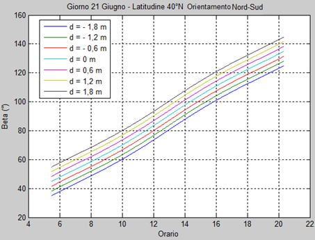
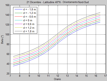
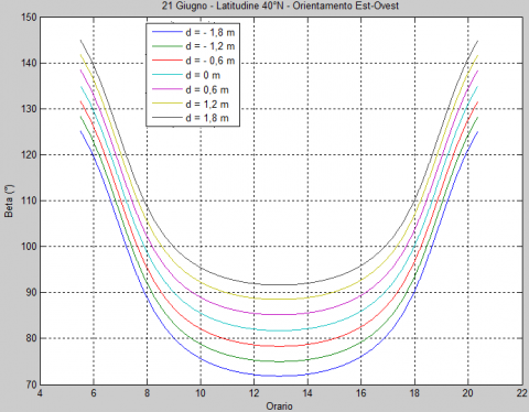
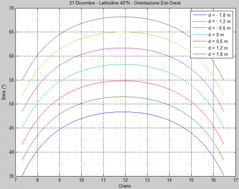
Figures 12 and 13 show the inclinations of the primary reflectors during the days 21 June and 21 December, in the event that the plant is oriented North-South.
It is possible to extend the validity of the equation even in the case in which the orientation is East-West. For this purpose, a mathematical artifice is used. It consists in modifying the value of the azimuth solar of 90°. In this way, instead of rotating the orientation of the plant, with relative changes to be made to the equation, the solar trajectory is rotated fictitiously, changing only the value of azimuth. In Figures 14 and 15 the inclinations of the mirrors are shown for the two days mentioned above in the case of East-West orientation.
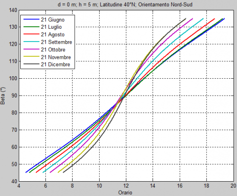
In Figures 16 and 17 the inclinations of mirror β under the tube are shown for different days and for different types of plant orientation.
Figure 12. Inclination of reflectors on June 21. h = 5 m. Latitude 40 °N. Orientation North-South
Figure 13. Inclination of reflectors on December 21. h = 5 m.Latitude 40 °N. Orientation North-South
Figure 14. Inclination of reflectors on June 21. h = 5 m.Latitude 40 °N. Orientation East-West
Figure 15. Inclination of reflectors on December 21. h = 5 m. Latitude 40 °N. Orientation East-West
Figure 16. Inclination of a reflector for different days. h =5m Latitude 40 °N. Orientation North-South
Figure 17. Inclination of a reflector for different days. h =5mLatitude 40 °N. Orientation East-West
When the solar altitude is low and the beam derives from the same direction as the implant, the rays reflected by mirrors do not completely illuminate the receiver tube (Figure 18).
Figure 18. Problem of reflection for an East-West plant
The segment of tube k in Figure 18, already introduced with Figure 7, represents the not radiated length of tube. The value of k can be obtained with reference to arc $\hat{k}$ of Figure 8:
$\mathrm{k}=\tan \hat{\mathrm{k}} \sqrt{\mathrm{d}^{2}+\mathrm{h}^{2}}$ (35)
This length is determined primarily by:
- sunpaths and, therefore, the latitude of the place, which is the reason why the use of Fresnel plants and their orientation is recommended for particular geographical areas;
- d and h parameters: the greater the distance between reflectors and absorber and the higher the value of k; in this sense, it is necessary to install the tube not too high.
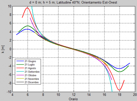
The optimal height h is the result of a geometrical compromise: the excessive height causes the loss of solar rays since k is high; the too low h generates shading and blocking and, thus, the panels must be adequately spaced, causing the loss of surface area occupied by the mirrors. In Figures 19 and 20 the trends of k for different days are shown. The main differences between the two types of orientation are:
- in the summer period: in the case of North-South orientation k values are maintained relatively low during the whole day; in the case of East-West orientation it reaches higher values, resulting zero at noon, when the insolation is maximum;
- in the winter period: in the case of North-South orientation segment k is always high and, therefore, a part of the pipe is never heated; in the East-West case, on the other hand, k is always low and the system is best exploited.
Figure 19. K length for different days. h = 5 mOrientation North-South
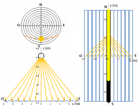
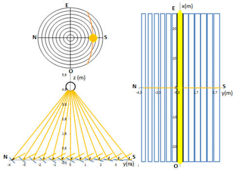
With reference to December 21 at noon, two plants with North-South orientation (Figure 21) and East-West (Figure 22) are shown. As previously mentioned the implants with North-South orientation are not able to irradiate the absorber tube completely in the winter period (Figure 21). A system with East-West orientation, instead, succeeds in directing the solar rays very well, especially at noon.
Figure 20. K length for different days. h = 5 mOrientation East-West
Figure 21. Orientation of the mirrors on December 21at noon in a North-South plant
Figure 22. Orientation of the mirrors on December 21at noon in an East-West plant
It is important to reiterate that the East-West solution is convenient at certain times of the year, while at other times it is less efficient than the North-South arrangement. The choice of the optimal orientation is influenced by the trends of k in the course of the year, which are functions of the geometrical characteristics of the plant (height of the tube, width of the reflectors) and the latitude of the location.
In the present work the operating characteristics of a linear Fresnel concentrator were analyzed. The main purpose is to identify mathematically the inclinations that the mirrors must assume in every moment of the day. The equation which defines the law of motion of the mirrors was determined. In accordance with this formula, it appears that the inclination of the mirrors is determined by:
• a term variable with the time, according only to the position of the Sun and, therefore, equal for all the reflectors;
• a term independent of time, characteristic of the position of the considered row of reflector.
It is demonstrated, therefore, that the inclinations which must assume the spotlight always maintain the same phase angle between themselves, at every moment of the day. Consequently, they must all rotate with the same angular speed and, therefore, can be handled by a single motor.
The proposed formula also allows the assessment instant by instant of the length of the tube which is not irradiated by the reflected rays, in relation to the orientation of the plant and the other geometric data.
|
a |
solar azimuth, degrees |
|
$\hat{\mathrm{b}}, \hat{\mathrm{k}}, \hat{\mathrm{x}}$ |
Construction angles, degrees |
|
d |
distance between tube and reflector, m |
|
h |
height of the tube, m |
|
k |
length of tube not irradiated, m |
|
L |
primary reflector width, m |
|
$\hat{\mathrm{n}}$ |
versor normal to primary reflector |
|
$\hat{\mathrm{n}}_{\mathrm{S}}$ |
sun’s rays versor |
|
$\hat{\mathrm{n}} \mathrm{t}$ |
reflected beam versor |
|
p, q, r |
sides of a generic spherical triangle, degrees |
|
$\mathfrak{p}, \hat{\mathfrak{q}}, \hat{\mathrm{r}}$ |
interior angles of a generic spherical triangle, degrees |
|
x |
abscissa, m |
|
y |
ordinate, m |
|
z |
distance between two adjacent mirrors, m |
|
Greeg Symbols |
|
|
α |
solar altitude, degrees |
|
β |
angle of inclination of reflector, degrees |
|
$\hat{\gamma}$, δ, θ |
construction angles, degrees |
|
ξ |
angle between normal of mirror and vertical axis, degrees |
|
ξ ' |
angle between normal of adjacent mirror and vertical axis, degrees |
|
φ |
angle between the longitudinal vertical plan and the plan linking the mirror line and the tube, degrees |
|
Subscripts |
|
|
A |
right end of reflector |
|
B |
left end of reflector |
|
T |
tube |
[1] Cannistraro A., Cannistraro G., Cannistraro M., Galvagno A. (2016). Analysis of the air pollution in the Urban center of four Sicilian cities, International Journal of Heat and Technology, Vol. 34, Sp. 2, pp. S219-S225. DOI: 10.18280/ijht.34S205
[2] Cannistraro A., Cannistraro G., Cannistraro M., Galvagno A., Trovato G. (2016). Evaluations technical and economic the integrations of co-trigeneration systems in the dairy industry, International Journal of Heat and Technology, Vol. 34, Sp. 2, pp. S332-S336. DOI: 10.18280/ijht.34S220
[3] Kaliakatsos D., Cucumo M., Ferraro V., Mele M., Cucumo S., Miele A. (2017). Performance of dish-stirling CSP system with dislocated engine, International Journal of Energy and Environmental Engineering, Vol. 8, No. 1, pp. 65-80. DOI: 10.1007/s40095-015-0183-z
[4] Cucumo M., Ferraro V., Kaliakatsos D., Mele M. (2015). Analysis of the performances of a dish-stirling system equipped with hot chamber, International Journal of Heat and Technology, Vol. 33, No. 4, pp. 125-136. DOI: 10.18280/ijht.330416
[5] Cucumo M., Kaliakatsos D., Marinelli V. (1997). General calculation methods for solar trajectories, Renewable Energy, Vol 11, No. 2, pp. 223-234. DOI: 10.1016/S0960-1481(96)00128-0
[6] Cucumo M., Ferraro V., Kaliakatsos D., Mele M., Nicoletti F. (2016). Calculation model using finite-difference method for energy analysis in a concentrating solar plant with linear fresnel reflectors, International Journal of Heat and Technology, Vol. 34, Sp. 2, pp. 337-345. DOI: 10.18280/ijht.34S221