OPEN ACCESS
It is difficult to analyze the heat transfer character of dry slag discharge system using the theory of computational heat transfer. It is necessary to develop an all-purpose and user-friendly temperature field research platform of dry slag discharge system to decrease difficulty and raise work efficiency. Based on the analysis on work mechanism of dry slag discharge system and the theory of computational heat transfer, this paper uses numerical calculation method to build the model of heat transfer between slags and air, packages the model in dynamic chained library for being called by visualization software, programs numerical simulation visualization software of dry slag discharge system with good interface in VB environment, discusses the procedures of system development and introduces the process of interface creation, procedures control and software integration. Taking dry slag discharge equipment of a power plant for example, numerical calculation and visualization display of heat transfer character is operated to offer more effective research platform for analyzing the heat transfer character of dry slag discharge system and designing equipment in optimization.
dry slag discharge system, heat transfer character, numerical calculation, visualization
Dry slag discharge technology has many advantages of saving water resource, high rate of comprehensively utilizing slag, environmental protection and so on. In the latest years, it has been widely used in power station boiler, circulating fluidized boiler and biomass boiler. [1-2] A large amount of physical heat in high-temperature slags can be recycled and utilized. Therefore, the design concept of dry slag discharge technology meets the policy of energy conservation and emission reduction and the thought of multi-grade utilization of energy. [3-4] Natural air is used as cooling medium in dry slag discharge system. In the negative pressure of hearth, the hot air after heat exchange in slag discharge machine enters furnace from its bottom. The air with relatively low temperature will influence stable burning, generation of NOx, flow field and the position of center of flame in hearth. It is the key of further improving and popularizing dry slag discharge system to clearly know the influence. [5-6]
With the development of computer technology, based on previous theories and experiments, Yang Kaimin [7] used software Fluent to make numerical simulation on air flow and heat transfer in dry slag discharge system. The comparison with experiment data indicates the data got from numerical calculation is almost same as experiment data. Han Liang [8] built coupled equation of convective heat transfer and radiative heat transfer for cooling hot slags based on the cooling process of slags in dry slag discharge machine and utilized computer coupling to get the distribution of the internal temperature field of dry slag discharge machine. Lu Mei [9] researched the influence of speed of transmission band and thickness of slags on heat transfer and temperature change of slags through numerical simulation on heat conduction and surface radiation coupling of mobile objects on the background of applying dry slag discharge technology.
At present, the research on numerical calculation of dry slag discharge system mainly aims at specific slag discharge equipment. The deep research on it needs specialized knowledge. Readability of the final result is not good and universality is insufficient. [10-11] Computer visualization technology is to use graph and image processing technology of computer to transform data to be graph or image and operate interactive processing. Visualization interface can avoid direct and monotonous program operation and lower the rate of error. In addition, graphical result can be directly displayed and easily understood.
This paper is based on the thought of modularization programing and the theory of computational heat transfer. Relatively independent heat transfer calculation module is built to be DLL file and called by VB visualization program. Data can be exchanged between them to achieve the visualization of modeling and analysis on the heat transfer character of dry slag discharge system and offer more effective approach to the design of and analysis on dry slag discharge equipment.
2.1 The model of heat transfer character of dry slag discharge system
Aiming at heat transfer, the model of heat transfer is a combination of heat conduction, convection and radiation no matter how complex structure of system is. The type of heat transfer to be considered and the main type of heat transfer may be different. [12-13] Based on the three heat transfer directions of heat transfer model in space, common heat transfer can be in zero-dimension, one dimension, two dimensions and three dimensions. In this paper, considering the work mechanism of dry slag discharge system, the heat transfer in width direction of conveyer belt is ignored; the heat transfer in movement direction of conveyer belt and the direction that is perpendicular to plane of conveyer belt is mainly researched.
2.2 Numerical calculation of dry slag discharge system
Figure 1. Simplified dry slag discharge machine
The main body of dry slag discharge system can be divided to be three layers in height direction. In other words, it can be divided to be upper layer, middle layer and lower layer by the interfaces of conveyer steel belt and return steel belt and the periphery of the outer wall of dry slag discharge machine.
Based on the overall structure of dry slag discharge system and the distribution of slags in different part of boiler, it is divided into three sections (slag drop section, flat section and slant section) in length direction for heat transfer calculation (Figure 1). Slag drop section is from entrance of slag well to the upper surface of slag layer on conveyer belt; heat transfer of radiation is the main way. Flat section is the part between the cross section of both peripheries of the exit of slag well; heat transfer of convection and radiation are the main ways. Slant section is from internal periphery of the exit of slag well to the cross section of normally open tuyere; convection is the main way. Figure 2 shows the analysis on heat balance of micro-body slag. The heat balance of micro-body slag Dx is analyzed.
Figure 2. Heat transfer model of micro control body of slags in the system
In unit time, the heat balance equation of slag layer is:
$Q_{x}+Q_{z}=Q_{x+d x}+Q_{f 1}+Q_{f 2}+Q_{d 1}+Q_{d 2}$ (1)
Where, $Q_{x}, Q_{x+d x}$—quantity of heat brought in and taken away by slags while entering and leaving control body in unit time, kJ/s; $\mathrm{kJ} / \mathrm{s} ; Q_{z}$—quantity of heat brought in by hot slags dropping from slag well in unit time, kJ/s; $ Q_{d 1}, Q_{d 2}$—quantity of convection heat between slags and upper air and that between slags and lower air in unit time, kJ/s; $Q_{f 1}, \cdot Q_{f 2}$—the quantity of radiation heat transferred from upper space and lower space to slags in unit time, kJ/s.
The heat exchange equations are substituted into slag layer heat balance equation and first-order differential equation of slag temperature distribution can be got:
$\frac{d T_{z}}{d x}=-\frac{h_{1}\left(T_{u p}-T_{a 1}\right)+h_{2}\left(T_{d o w n}-T_{a 2}\right)+\varepsilon_{s 1} \sigma\left(T_{u p}^{4}-T_{w 11}^{4}\right)+\varepsilon_{w 11}^{4}-T_{w 12}^{4} )+\varepsilon_{s 3} \sigma\left(T_{d o w n}^{4}-T_{d b}^{4}\right)+\varepsilon_{s t} \sigma\left(T_{d o w n}^{4}-T_{w 2}^{4}\right)}{C_{p z} \rho_{z} u w \delta}$ (2)
where, u-speed of conveying chain, m/s; w-width of slag layer, m; $C_{p z}$-specific heat of slag, kJ/(kg·K); $\rho_{Z}$-density of slag, kg/m3; $\delta$-thickness of slag layer, m; $l_{2}$—the length of slant section of dry slag discharge machine, m; $T_{u p}$-temperature of the upper surface of slag layer, K; $T_{\text { down }}$-temperature of the lower surface of slag layer, K; $T_{a 1}$-temperature of upper air, K; $T_{a 2}$-temperature of air at middle layer, K; $T_{d b}$-temperature of conveying chain and return chain, K; $T_{w 2}$-temperature of shell between two conveying chains, K.
The flow direction of air is opposite to the movement direction of slags. It enters the system from the tuyere of slag discharge machine, exchanges heat with the hot slags on conveyor belt, flows out from slag well and reaches hearth to support burning. The circulation channel of upper air can be simplified to be a rectangular pipeline. It exchanges heat with pipe wall and slags.
Based on heat balance of upper air, first-order differential equation of the distribution of air temperature can be got finally:
$\frac{d T_{a 1}}{d x}=\frac{h_{1}\left(T_{u p}-T_{a 1}\right) w-h_{5}\left(T_{a 2}-T_{d b}\right) w-2 h_{6}\left(T_{a 2}-T_{w 2}\right) L_{2}}{C_{p a} \rho_{a} V_{a 3} L_{3}}$ (3)
where, $C_{p a}$-specific heat of air, kJ/(kg·K); $\rho_{a}$-density of air, kg/m3; $L_{1}$-distance between top of shell and upper layer of slag, m; $V_{a 1}$-flow velocity of upper air, m/s.
To guarantee the precision of calculation, modified Eulerian method (special second-order Runge-Kutta method) is used for iterative computation and solving the equation of slag temperature and air temperature distribution. [14-15] The main thought of modified Eulerian method:
Predict the next value firstly and get preliminary approximate value:
$y_{n+1}=y_{n}+h f\left(x_{n}, y_{n}\right)$ (4)
Use trapezoidal equation to rectify approximate value and get rectified value:
$y_{n+1}=y_{n}+\frac{h}{2}\left[f\left(x_{n}, y_{n}\right)+f\left(x_{n+1}, \overline{y}_{n+1}\right)\right]$ (5)
where, h is step size of calculation; xn and xn+1 are the calculation node of the nth step and n+1th step, respectively; yn and yn+1 are the calculation value of the nth step and n+1th step, respectively.
This paper is based on the heat transfer model of different sections of dry slag discharge system, uses their coupling relation, applies modified Eulerian method to make corresponding C language calculation program, gets the parameters of heat transfer of dry slag discharge system and gets the distribution of slags in system and temperature of air.
3.1 General framework of system
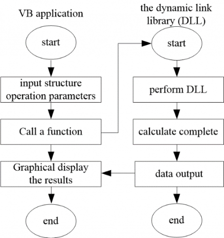
Dry slag discharge system is based on VB and achieves hybrid programming of VB and VC; human-computer interaction interface and heat transfer model of dry slag discharge system are designed; and analysis result is output. General framework of the whole system is shown in Figure 3.
Figure 3. General framework of dry slag discharge system
3.2 Visualization procedures
Figure 4 shows the visualization flow of the whole system. Start VB application program and input parameters of dry slag discharge system. The parameter collective includes operating parameters and structure parameters of dry slag discharge system. The parameters can determine an operating status of dry slag discharge system. The operation assigns visualization program, calls DLL file of dynamic chained library, transfers parameters into the function in DLL, starts calculation and gets resultant data. The resultant data includes the temperature of slags at each position of conveyor belt and the temperature of its upper air, the temperature of air at exit of the dry slag discharge system and the temperature of slags at exit of the dry slag discharge system. The resultant data is saved as graph and returned to VB. Users choose the result to be shown and VB shows the result. The whole process ends.
Figure 4. Visualization flow chart of the heat transfer character of dry slag discharge system
4.1 The method of VB program calling DLL
Visual Basic is a visualized, object-oriented and time-driven structuring software design language. Its efficiency of algorithm and numerical processing and analysis is much lower than that of C language. Dynamic library technique is often used in program design. It is an important technical means of achieving resources sharing in application program, saving memory space and raising efficiency of use. Therefore, they are combined in this paper. VB is used as interface customization tool of the whole system; DLL in VC is used as supporting tool of background data processing. This makes their respective advantages complementary to each other. While guaranteeing calculation speed, the quantity of software codes can be reduced and work load of code maintenance can be relieved.
In the calculation process of heat transfer model, large quantity of iterations is needed. As a language that produces high-quality target codes and has high efficiency of program execution, C language can be executed in high speed and has good performance of transportability. This paper packs calculation functions in C language in dynamic chained library. The advantage of fast execution of C language is utilized; at the same time, the change and modification of calculation module (DLL file) does not influence other parts of visualization software. This meets the programing thought of modularization.
Some codes of declaration function of heat transfer model DLL in visualization software are:
Private Declare Function Change Lib "dll8_19h.dll" (ByVal x As Double) As Double ', _
ByVal a As Double, ByVal b As Double, ByVal c As Double) As Double
Private Declare Function Cal Lib "dll8_19h.dll" (ByRef canshu1 As Double, _
ByRef t1 As Double, ByRef tk1 As Double, ByRef tk3 As Double, …) As Integer
Some codes of calling function of heat transfer model DLL in visualization software are:
Private Sub mnuRun_Click ()
The living example of dynamic chained library DLL is created in this way. After calling is completed, VB program can call dynamic chained library using two functions of Change (transfer data) and Cal (execute command of the calculation functions of heat transfer model). These functions greatly contribute to developing medium functions of VB and VC.
4.2 Design of the visualization system of dry slag discharge system
Taking the typical operation of dry slag discharge equipment of 300MW unit in certain power plant, the operating process and functions of visualization heat transfer character calculation software of dry slag discharge system are shown. The main interface of visualization system is shown in Figure 5, including list of parameters, panel of parameters, graph window, transcript window and shortcut display column of parameters.
Figure 5. The main interface of visualization system
Calculation parameters are divided into two categories in the list of parameters: structure parameters and calculation scheme. The original model size of dry slag discharge system can be independently designed in the dialogue box of structure parameters, mainly including the size of slant section and flat section of the system, the size of internal conveyor steel belt and height of space. The combination of size of all sections can determine the size of the whole slag discharge system. The calculation scheme contains the parameters of quantity of slags, speed of steel belt and the status (open or closed) of tuyere. In different operational states, the heat transfer parameters of dry slag discharge system (such as the variation trend of temperature of slags and air) are considerably different.
Figure 6 and Figure 7 are the interfaces of heat transfer calculation results display of the dry slag discharge system. After calling DLL file and the iterative calculation of heat transfer calculation function ends, Figure 6 shows the heat transfer parameters of dry slag discharge system, including the temperature of the feature positions of inlet and outlet. When clicking any fracture surface on schematic diagram of the system, temperature of slags and air on the fracture surface can be displayed on text window. The change of color in schematic diagram of the system directly reflects the temperature change of air in slag discharge system and indirectly reflects the heat transfer in system. Blue means normal temperature; the redder color is, the higher temperature of air is.
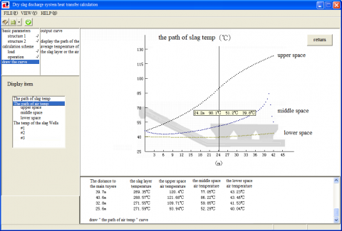
Figure 7 shows three trend curves of temperature of air in flow direction at upper layer, middle layer and lower layer in the dry slag discharge system. The trend curves matching the schematic diagram of the system in light color help to visually understand the meaning of the curves and help users to search corresponding heat transfer parameters at certain position of the system.
Figure 6. Results display interface of the visualization system
Figure 7. Graphic results display of the visualization system
This paper researches the visualization of heat transfer character of dry slag discharge system based on higher theory of heat transfer and object-oriented software technology. Firstly, the heat transfer model of dry slag discharge system is built through analyzing the heat transfer mechanism of dry slag discharge system and using infinitesimal method and modified Eulerian method. Secondly, numerical calculation program of heat transfer character of dry slag discharge system is made based on VC and packaged to be dynamic chained library. Thirdly, the visualization of heat transfer parameters is achieved in VB environment. Finally, taking dry slag discharge equipment of 300MW unit in certain power plant for example, numerical calculation and analysis on heat transfer character of the system is operated. The research in this paper offers a new approach for the research on safe operation and heat transfer character of dry slag discharge system of the boiler in power plant. In addition, it helps to raise efficiency of research.
This paper was supported by Hebei Province Colleges & Universities Scientific Research Program, Youth Foundation (No. QN2016204).
[1] Sil I., Mukherjee S., Biswas K. (2017). A review of energy harvesting technology and its potential applications, Environmental and Earth Sciences Research Journal, Vol. 4, No. 2, pp. 33-38. DOI: 10.18280/eesrj.040202
[2] Ravindra D., Kali P., Ajay K.S., Sabita S., Marutiram K. (2016). Experimental study of rotating dry slag granulation unit: Operating regimes, particle size analysis and scale up, Applied Thermal Engineering, Vol. 107, No. 25, pp. 898-906. DOI: 10.1016/j.applthermaleng.2016.07.049
[3] Deng L., Tan X., Tang C., Che D. (2016). A study on water-quenching waste heat recovery from molten slag of slag-tap boilers, Applied Thermal Engineering, Vol 108, pp. 538-545. DOI: 10.1016/j.applthermaleng.2016.07.169
[4] Sun Y., Shen H., Wang H., Wang X., Zhang Z., (2014). Experimental investigation and modeling of cooling processes of high temperature slags, Energy, Vol 76, No 11, pp. 761-767. DOI: 10.1016/j.energy.2014.08.073
[5] Duan W., Yu Q., Wang Z., Liu J., Qin Q., (2018). Life cycle and economic assessment of multi-stage blast furnace slag waste heat recovery system, Energy, Vol 142, No 9, pp. 486-495. DOI: 10.1016/j.energy.2017.10.048
[6] Shi W., Dai X., Bai J., Kong L., Li W. (2018). A new method of estimating the liquidus temperature of coal ash slag using ash composition, Chemical Engineering Science, Vol 175, No 1, pp. 278-285. DOI: 10.1016/j.ces.2017.10.002
[7] Yan K., Yan M. (2008). Numerical simulation of flow and heat transfer in the dry slag removal system of a boiler, Journal of Engineering Thermophysics, Vol. 29, No. 11, pp. 1930-1932. DOI: 10.3321/j.issn:0253-231X.2008.11.033
[8] Han L., Chen H. (2011). Numerical calculation of heat exchange parameters for dry-type slag removal system. power equipment, Vol. 25, No. 6, pp. 388-391. DOI: 10.3969/j.issn.1671- 086X .2011.06.003
[9] Lu M., Yang M. (2003). Numerical computation on heat conduction coupled with surface radiation for a moving body, Journal of Engineering Thermophysics, Vol. 24, No. 4, pp. 637-639. DOI: 10.3321/j.issn:0253-231X.2003.04.027
[10] Bisio G. (1997). Energy recovery from molten slag and exploitation of the recovered energy, Energy, Vol. 22, No. 5, pp. 501-509. DOI: 10.1016/s0360-5442(96)00149-1
[11] Zhang H., Wang H., Zhu X., Qiu Y., Liao Q. (2013). A review of waste heat recovery technologies towards molten slag in steel industry, Applied Energy, Vol 112, No 12, pp. 956-966. DOI: 10.1016/j.apenergy.2013.02.019
[12] Duan W., Yu Q., Zuo Z., Qin Q., Li P., Liu J., (2014). The technological calculation for synergistic system of BF slag waste heat recovery and carbon resources reduction, Energy Conversion and Management, Vol. 87, No. 11, pp. 185-190. DOI: 10.1016/j.enconman.2014.07.029
[13] Miao L., Wu W., Nadine A., Mehrdad M. (2014). Heat transfer and flow of a slag-type non-linear fluid: Effects of variable thermal conductivity, Applied Mathematics and Computation, Vol. 227, No. 1, pp. 77-91. DOI: 10.1016/j.amc.2013.11.010
[14] Medina Y.C., Khandy N.H., Fonticiella O.M.C., Morales O.F.G. (2017). Abstract of heat transfer coefficient modelation in single-phase systems inside pipes, Mathematical Modelling of Engineering Problems, Vol. 4, No. 3, pp. 126-131. DOI: 10.18280/mmep.040303
[15] Alam M.S. (2016). Mathematical modelling for natural convective heat transfer of nanofluid inside a prismatic enclosure with various thermal boundary conditions, Mathematical Modelling of Engineering Problems, Vol. 3, No. 4, pp. 162-170. DOI: 10.18280/mmep.03040