OPEN ACCESS
In view of the low efficiency of coal breakage by high-pressure gas jet, this paper put forward a new method of efficient coal breakage method by abrasive gas jet (AGJ). According to the theory of aerodynamics theory, the nozzle structure was established. On this basis, the influence rule of jet parameters on the velocity and erosion rate of abrasive was studied by numerical simulation. Moreover, the experiment explored the relationship of the pressure of high-pressure abrasive jet and the target distance with the erosion depth, the erosion volume as well as the diameter of the erosion pit. According to the experimental results, based on the engineering application parameter range, when the jet pressure was 15MPa, the erosion rate was the largest and the erosion effect was the optimum on the premise of definite target distance. The erosion depth and erosion volume increased with the jet pressure. When the pressure was greater than 15MPa, the erosion depth and erosion volume did not increase obviously. The diameter of erosion pit was basically constant as the change of pressure. In the case of the definite jet flow pressure, the erosion depth first increased and then decreased with the increase of the target distance. The erosion volume and erosion pit diameter were in direct proportion to the target distance. Based on the comparative analysis of erosion depth, erosion volume, and erosion pit diameter, it has been determined that the optimal jet pressure of the abrasive gas is 15MPa, and the optimum target distance of jet flow is about 10cm.
abrasive gas jet (AGJ), coal and rock breakage, laval nozzle, water jet
As a kind of clean energy, coal-bed methane has been increasingly concerned and studied. In China, coal-bed methane extraction is divided into underground extraction and over ground extraction. Underground extraction accounts for 60%. However, due to the poor permeability of coal seam in China, the efficiency of underground coal-bed methane extraction is relatively low. To this end, scholars have put forward the hydraulic measures such as high-pressure water jet cutting [1], hydraulic punching [2-3], and hydraulic fracturing [4-5] to relieve the pressure and enhance the permeability so as to intensify the coal-bed methane extraction. Nonetheless, the water introduced in the coal-bed methane extraction intensified by hydraulic measures will inhibit the migration and desorption of coal-bed methane [6]. Therefore, pneumatic measures such as liquid carbon dioxide phase change cracking technology [7], nitrogen and carbon dioxide displacement [8-9] and coal erosion and breakage through supercritical carbon dioxide [10-11] have been gradually popularized and applied, and utilized as the important supplement of hydraulic measures. Coal breakage and permeability enhancement measure through high-pressure gas jet has the advantages of the simple process and easy preparation of high-pressure gas [12]. It mainly utilizes the impact load and the stress wave propagation to break the coal and generate tiny cracks and surface erosion pits in coal. However, the depth of coal breakage is not enough, and the coal breakage effect is not obvious. Moreover, the high gas pressure limits its application. Therefore, this paper proposes a coal breakage method by abrasive gas jet based on the coal breakage by high-pressure gas jet.
The key to popularize and apply coal breakage and permeability increase by high-pressure abrasive gas jet is the abrasive gas jet parameters. Different from the water jet, the gas jet structure is influenced by jet pressure, namely, the ratio of pressure at inlet and outlet of nozzle [13]. Therefore, the jet erosion parameters of water jet cannot be directly utilized in the abrasive gas jet. At present, research on the coal breakage by erosion of abrasive gas jet is scarce. It is of great significance for the abrasive gas jet to study abrasive jet erosion parameters. Furthermore, selection of the appropriate parameters of jet erosion exerts great influence on the improvement of erosion effect.
Abrasive particles and high-pressure air are expelled through a nozzle to form abrasive gas jet(AGJ). As a kind of supersonic speed flow, abrasive gas jet is hard to be analyzed by experiment. However, the numerical simulation can descript the flow field structure precisely and get more data. Quan Dong have verified the numerical simulation’s reliability by contrastive analysis with experiment [14]. RNG k-ε turbulence model can simulate precisely the flow field structure of supersonic flow, the results are consistent with the experimental results [15-16]. S.P. Kiselev analyzed the abrasive flow character and target impact of supersonic nozzle with numerical simulation [17]. L.A. Florio and T. A. Sedrez analyzed the target erosion rate when abrasive gas jet flow with numerical simulation and experiment [18-19].
This paper combined numerical simulation and experiment to study the influence of jet pressure and jet target distance on erosion effect so as to obtain the optimum jet pressure and the optimal target distance of coal breakage by abrasive gas jet.
2.1 Nozzle parameter
This paper mainly studies the influence of abrasive gas jet pressure and jet target distance on erosion effect. For the abrasive gas jet, the energy obtained by abrasive from the gas plays a decisive role in jet effect. The common nozzles include convergent nozzle and Laval nozzle. Because of the compressibility of the gas and the lack of divergent segment, the velocity reaches to maximum at the nozzle outlet and forms shock wave. So, the jet flow filed structure isn’t optimal, the abrasive can’t accelerate sufficiently either. The maximum velocity at the outlet of the convergent nozzle can only be the sound velocity, namely, subsonic jet. In contrast, the Laval nozzle can obtain supersonic gas jet. The length and angel of divergent segment control the expansive degree of gas jet and form optimal flow field structure. Therefore, the Laval nozzle is selected to study the parameters of high-pressure abrasive gas jet.
A Laval nozzle is composed of three parts of inlet stability section, convergent section, and the divergent segment. Steady and uniform gas flow can be obtained in the inlet stability section. The convergent section accelerates the gas flow to sound velocity. Finally, supersonic gas flow is obtained in the divergent segment [20]. The size of the Laval nozzle is designed and calculated according to the gas dynamics principle [21-22]. The mass flow of any section of the nozzle is:
$m=\frac{P_{0} A}{\sqrt{R T_{0}}} \sqrt{\frac{2 k_{0}}{k_{0}-1}\left[\left(\frac{p}{P_{0}}\right)^{\frac{2}{k_{0}}}-\left(\frac{p}{P_{0}}\right)^{\frac{k_{0}+1}{k_{0}}}\right]}$ (1)
The area ratio of different sections of the nozzle is:
$\frac{A}{A_{0}}=\frac{1}{M_{a}}\left(\frac{2}{k_{0}+1}\right)^{\frac{k_{0}+1}{2\left(k_{0}-1\right)}}\left(1+\frac{k_{0}-1}{2} M_{a}^{2}\right)^{\frac{k_{0}+1}{2\left(k_{0}-1\right)}}$ (2)
The outlet velocity of the nozzle is:
$v=\sqrt{\frac{2 k_{0}}{k_{0}-1} R T_{0}\left[1-\left(\frac{P}{P_{0}}\right)^{\frac{k_{0}-1}{k_{0}}}\right]}$ (3)
The outlet temperature of the nozzle is:
$T_{2}=T_{0}\left(\frac{P}{P_{0}}\right)^{\frac{k_{0}-1}{k_{0}}}$ (4)
Mach number:
$M_{a}=\frac{v}{\sqrt{k_{0} R T}}$ (5)
where, T0 is stagnation temperature (K). P0 is stagnation pressure (Pa). k0 is adiabatic index, k0=1.4;R is gas constant. m is mass flow (kg/s). A and A0 are areas of the sections. Ma is the Mach number. T2 is the outlet temperature of the nozzle.
The convergent angle and divergent angle of the nozzle are valued according to the experience [23-24]. Generally speaking, the convergent angle is 30°, and the divergent angle is 10°. When the temperature is 300K and the pressure is 15 MPa, the measured mass flow of the inlet gas is 0.096kg/s. Because of the characteristics of the Laval nozzle, the Mach number at the nozzle throat is Ma=1. According to the above formula, the diameter of the nozzle inlet is d=6mm, the diameter of the nozzle throat is d0=2mm, and the diameter of the nozzle outlet is D=8mm. The length of the convergent section is L2=7.4mm, and the length of the divergence segment is L3=34.3mm. The length of the inlet stability section is L1=6mm. Therefore, the nozzle structure is as shown in Figure 1.
Figure 1. The structure of Laval nozzle
2.2 Numerical simulation model
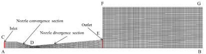
Considering the symmetry of the Laval nozzle structure, the two-dimensional model can be utilized for the calculation in the numerical simulation. That is, half of the actual flow area is utilized as the calculation model to divide the grid. The calculation area mainly includes the nozzle and free jet region. According to the actual size of nozzle, the flow field model of nozzle and the free flow field at the nozzle outlet were established by the software GAMBIT. The grid is divided through the quadrilateral structured grid. Considering the difference of target distance, this paper only gives a grid model, as shown in Figure 2, where AB is symmetric boundary, AC is the pressure inlet boundary, CDE is non-slip adiabatic wall, EFG is the pressure outlet boundary, and BG is the wall of the jet erosion, which can reflect the erosion effect of abrasive gas jet. It is a kind of boundary condition which is non-slip boundary condition.
To test the mesh independence, the outlet velocities of gas jet have been compared to the condition of different mesh number, such as 16289, 36850, and 65,729. The results are as follows.
Figure 2. The mesh generation of nozzle and flow field
Table 1. The mesh independency study
|
Mesh number |
Nozzle outlet velocity (m/s) |
Maximum calculation error |
|
16289 |
688.032 |
0.21% |
|
36850 |
687.042 |
|
|
65729 |
686.606 |
The results of grid-independent verification show that it is reliable to use 36,850 mesh structures to calculate.
In this experiment, the 120-mesh quartz sand abrasive was adopted, and the Moh's hardness was 7. In order to compare with the experimental results, the numerical simulation adopted the 120-mesh quartz sand abrasive. The density was 2660kg/m3, diameter is 0.125mm, and the mass flow of the abrasive was 0.01kg/s. The initial velocity of the abrasive was 0. The outlet pressure was barometric pressure, 101.325kpa. The parameter values of the numerical simulation are shown in Table 2.
Table 2. Parameter values of the numerical simulation
|
Parameter |
Fixed parameter |
Simulation variable |
|
Inlet pressure |
Target distance: 7cm |
p=5 MPa |
|
p=10 MPa |
||
|
p=15 MPa |
||
|
p=20 MPa |
||
|
p=25 MPa |
||
|
Target distance |
Inlet pressure: 15MPa |
1cm |
|
4cm |
||
|
7cm |
||
|
15cm |
||
|
25cm |
2.3 Calculation model
Numerical simulation adopted the DPM discrete term model in Fluent to simulate the movement erosion of abrasive particles. Firstly, the gas flow field was calculated. When the gas flow field converged, the discrete term was added. This paper adopted RNG k-ε turbulence model, and the N-S equation was solved through the finite volume method. Compared with k-ε model, the accuracy of the simulation is higher. The fluid is ideal gas, and the RNG k-ε turbulence model is described as follows:
$\frac{\partial(\rho k)}{\partial t}+\frac{\partial\left(\rho k u_{i}\right)}{\partial x_{i}}$$=\frac{\partial}{\partial x_{j}}\left[\alpha_{k} \mu_{e f f} \frac{\partial k}{\partial x_{j}}\right]+G_{k}+G_{b}-\rho \varepsilon-Y_{M}$ (6)
$\frac{\partial(\rho \varepsilon)}{\partial t}+\frac{\partial\left(\rho \varepsilon u_{i}\right)}{\partial x_{i}}=\frac{\partial}{\partial x_{j}}\left[\alpha_{\varepsilon} \mu_{e f f} \frac{\partial \varepsilon}{\partial x_{j}}\right]$$+C_{1 s}^{*} \frac{\varepsilon}{k}\left(G_{k}+C_{3 \varepsilon} G_{b}\right)-C_{2 \varepsilon} \rho \frac{\varepsilon^{2}}{k}-R$ (7)
where,
$C_{1 \varepsilon}^{*}=C_{1 \varepsilon}-\frac{\eta\left(1-\eta / \eta_{0}\right)}{1+\beta \eta^{3}}$
$\eta=\left(\alpha E_{i j} \cdot E_{i j}\right)^{1 / 2} \frac{k}{\varepsilon}$
$\mu_{e f f}=\mu+\mu_{t}$
$\mu_{t}=\rho C_{u} \frac{k^{2}}{\varepsilon}$
$G_{b}=\beta g_{i} \frac{\mu_{t}}{\operatorname{Pr}_{t}} \frac{\partial T}{\partial x_{i}}$
$G_{k}=\mu_{t}\left(\frac{\partial \mu_{i}}{\partial x_{j}}+\frac{\partial \mu_{j}}{\partial x_{i}}\right) \frac{\partial \mu_{i}}{\partial x_{j}}$
$Y_{M}=2 \rho \varepsilon \frac{k}{a^{2}}$
where, Gk is the production item of turbulent kinetic energy k caused by the mean velocity gradient. Gb is the production item of turbulent kinetic energy caused by buoyancy. YM is the influence of compressible turbulent fluctuation on the total dissipation rate. αk and αε are the reciprocals of effective Prandtl numbers of turbulent kinetic energy and dissipation rate, respectively. Prt is turbulent Prandtl number. C1ε, C2ε and C3ε are empirical constants. gi is the component of gravitational acceleration in the i direction. is the coefficient of thermal expansion, and a is the sound velocity.
2.4 Numerical simulation results
According to the velocity formula of nozzle outlet, the outlet velocity of nozzle under different jet pressure could be calculated theoretically, as shown in Figure 3. It can be observed that the velocity of the outlet gas increased with the inlet pressure, and the increased speed gradually slowed down. When the inlet pressure was greater than 15MPa, the increase of gas velocity became increasingly smaller. Therefore, the jet velocity was increasingly less affected by simply enhancing the jet pressure. Under certain conditions, the optimal pressure exists for the abrasive jet.
Figure 3. Relationship between gas jet velocity of nozzle outlet and jet pressure
Figure 4. Relationship between abrasive velocity and jet pressure
According to the abrasive velocity change curve under the different inlet pressure as shown in Figure 4, with the increase of the inlet pressure, the abrasive velocity first increased rapidly. When the pressure was greater than 10MPa, the increased of abrasive velocity slowed down. When the pressure was between 20MPa and 30MPa, the abrasive velocity was relatively stable. The power of abrasive particles of high-pressure abrasive gas jet was from the high-pressure gas. According to the change of gas velocity as shown in Figure 4, when the inlet pressure was less than 10MPa, with the increase of pressure, the gas velocity at the inlet of the nozzle increased substantially. When the inlet pressure was greater than 10MPa and smaller than 20MPa, with the increase of pressure, the increase of the gas phase velocity became slow. When the inlet pressure was greater than 20MPa, the increase of gas velocity was slight. The change of the velocity of the abrasive particle of the abrasive gas jet was consistent with the change trend of gas velocity with pressure.
Fluent was adopted to carry out numerical simulation. The erosion rate module can directly reflect the erosion rate of the target [25], namely, the quality of the material removed per unit area per unit time. In Fluent, the erosion rate was defined as:
$R_{\text {erosion}}=\sum_{p=1}^{N \text { particle }} \frac{m_{p} C\left(d_{p}\right) f(\alpha) v_{p}^{b(v)}}{A_{\text { face }}}$ (8)
where, C(dp) is particle size function; α is the impact angle between the particle path and the wall surface. f(α) is the impact angle function. v is the relative velocity of particles. b(v) is the relative velocity function of particles. Aface is the area of the wall.
Table 3. The erosion rate of target
|
Inlet pressure(MPa) |
10 |
15 |
20 |
25 |
|
Erosion rate(kg/m2·t)×10-8 |
1.19 |
4.58 |
3.6 |
4.0 |
In this paper, erosion rate obtained by erosion model is the erosion rate at the same time. According to the simulation results, it is found that the erosion rate is approximately parabolic with the change of the jet pressure. When the pressure was 15MPa, the erosion rate was the largest. When the jet pressure increased, the abrasive velocity was higher. When the abrasive impacted the target, the velocity of the abrasive rebound was larger, which further affected the incoming abrasive and the jet flow effect. Therefore, within a certain range of jet pressure, the jet erosion effect was better when the injection pressure was 15MPa.
Figure 5. Gas jet velocity under different target distances
Figure 6. Relationship between target distance and abrasive velocity
Figure 5 shows the change curve of gas velocity with the target distance when the inlet pressure was 15MPa. It can be observed that the velocity of gas phase was fluctuant when the target distance was between 0 and 12cm. In the case that the target distance was greater than 12cm, the gas velocity began to obviously decrease. As shown in Figure 6, when the pressure was constant, the velocity of abrasive particles increased with the target distance. This indicates that the kinetic energy of the gas was converted into the kinetic energy of the abrasive in the acceleration process of gas expansion at the nozzle outlet. When the target distance was greater than 13cm, the abrasive velocity was basically unchanged. At this moment, the gas velocity began to decrease. The acceleration of the abrasive was limited, and the velocity increased gently. In the movement process of abrasive particles, the abrasive velocity was always smaller than the gas velocity.
The erosion effect of abrasive gas jet depends on the energy obtained by abrasive particles. Therefore, a better jet erosion effect can be obtained by choosing appropriate jet pressure and target distance. According to the results of numerical simulation, it can be found that the optimal jet pressure is 15MPa.
3.1 Experimental system
The experimental system is composed of air compressor, pressure gauge, abrasive tank and operation box. The maximum pressure of the air compressor is 40MPa, and the nozzle is a convergent nozzle. Higher pressure raises higher requirements on system device. Considering the engineering application, the maximum pressure in the experiment was selected as 25MPa. The system connection is shown in Figure 7. In the coal breakage experiment, the diameter of the coal sample is 50×100mm, and the abrasive is 120-mesh quartz sand. The mass flow of the abrasive was 0.01kg/s. Jet pressure was 15MPa. At the erosion time of 15s, the coal pillar was seriously broken, and the erosion depth was up to 64.8mm. Breakage and fragment occurred in the middle of the coal pillar. In the coal sample experiment, the erosion effect parameter cannot be accurately measured. Therefore, limestone was adopted to carry out the regular experiment. The limestone was processed into standard samples with the size of 100mm×100mm×100mm.
Figure 7. System devices of abrasive gas jet
Figure 8. Coal breakage effect of abrasive gas jet
3.2 Analysis of experiment results
In the experiment, the abrasive was 120-mesh quartz sand. The erosion time was 15s. The mass flow of the abrasive was 0.01kg/s. On this basis, the coal breakage experiment was carried out to analyze the influence of jet pressure and jet target distance on erosion effect.
3.2.1 Jet flow pressure
In the experiment, the target distance was 7cm. The jet flow pressure was set as 5, 10, 15, 20 and 25MPa, respectively. The influence rule of jet flow pressure on erosion effect was studied by comparative analysis on the erosion volume, erosion depth and erosion pit diameter.
Figure 10~Figure 12 show the variation curves of erosion depth, erosion volume and erosion pit diameter with pressure. With the increase of the jet flow pressure, the depth and volume of the erosion pit continuously increased. When the jet pressure was below 15MPa, the erosion depth and erosion volume changed greatly. When the pressure was enhanced from 10MPa to 15MPa, the erosion depth was increased by 15.2mm, and the erosion volume was increased by 4ml. When the pressure was enhanced from 15MPa to 25MPa, the erosion depth was increased by 1.52mm. In the case of the fixed jet target distance, the diameter of the erosion pit was basically unchanged. This is because the kinetic energy of the abrasive particles increased with the jet pressure in the jet flow process, and the erosion effect would be better. However, the kinetic energy of the particles was greater. After the abrasive particles impacted the target, the rebound effect was strengthened, which affected the jet flow effect. Therefore, when the pressure was greater than 15MPa, jet breakage effect was not obviously improved with the increase of jet pressure. Based on the comparison of erosion depth and erosion volume, the coal breakage by abrasive gas jet has the optimum jet pressure. It can be discovered that the pressure of 15MPa can get better jet erosion effect.
Figure 9. Erosion effects under different jet flow pressure
Figure 10. Relationship between erosion depth and jet flow pressure
Figure 11. Relationship between erosion volume and jet flow pressure
Figure 12. Relationship between erosion pit diameter and jet flow pressure
3.2.2 Target distance
For abrasive gas jet, the target distance is a critical factor. There is an optimal target distance and the maximum target distance in the abrasive gas jet. The optimal target distance determines the rock breakage efficiency of the abrasive gas jet, and the maximum target distance affects the range of the coal or rock can be broken. Presently, optimal target distance has been studied mostly. Oppositely, maximum target distance is rarely studied. In this paper, we have studied the influence of both target distance on rock breakage with abrasive gas jet.
The experimental pressure was 15MPa, and the target distance was 1cm, 4cm, 7cm, 10cm, 15cm and 25cm, respectively. The influence rule of jet target distance on erosion effect was studied.
Figure 13. Jet flow effects under different target distances
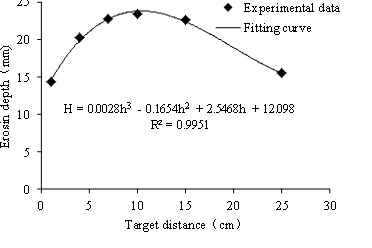
Figure 14. Relationship between erosion depth and jet flow target distance
Figure 15. Relationship between erosion volume and jet flow target distance
Figure 16. Relationship between erosion pit diameter and jet flow target distance
As shown in Figure 14~Figure 16, with the increase of the target distance, the erosion depth increased first and then decreased, and erosion volume and erosion pit diameter increased continuously. The distribution of abrasive is consistent with the structure of the gas flow field in the abrasive jet flow. With the increase of the target distance, the gas jet diffused gradually, and which caused the divergence of the abrasive. When the target distance was small, the abrasive will form the abrasive layer covering the surface of the target in the jet flow process, which affected the jet flow breakage effect. When the jet target distance was larger, the divergent abrasive distribution resulted in the dispersion of abrasive energy, which also affected the impact breakage effect. Finally, the diameter of the jet erosion pit was continuously extended, and the erosion depth decreased.
Through the experimental data, we have fit the relationship between erosion depth and target distance, shown as follows:
H=0.0028h3-0.1654h2+2.5468h+12.098 (9)
where, H is erosion depth, cm; h is target distance, cm. Correlation coefficient R2=0.9951, so the erosion depth of other targets can be predicted by fitting formula. Also, according to the fitting curve of jet target distance and erosion volume, the fitting formula is as follows:
V=-0.0005h3+0.0094h2+0.3553h+0.5509 (10)
where, V is erosion volume, ml; h is target distance, cm. Correlation coefficient R2=0.986.
Therefore, the optimal target distance existed when the high-pressure abrasive gas jet was adopted for coal breakage. The erosion effect should be measured by comprehensively comparing erosion depth and erosion volume. That is, both the erosion depth and the erosion volume should meet the definite requirements. Based on the comparison of erosion depth and erosion volume and fitting curve, when the target distance was about 10cm, the jet flow erosion effect was better.
(1) A novel method of coal and rock breakage with abrasive gas jet has been proposed. The method is more efficient in coal and rock breakage compared to the gas jet which forms small erosion pit and crack on the coal or rock surface merely.
(2) The velocity filed and erosion effect of abrasive gas jet have been studied by Fluent, and it can be concluded that the optical pressure of coal breakage is 15MPa.
(3) The relationship between gas jet pressure and erosion depth have been studied via experiment of coal and rock breakage with abrasive gas jet flow. With the increase of the gas jet pressure, the erosion depth and erosion volume begin to increase rapidly, and then tend to be steady. So, there is optimal gas jet pressure for coal or rock breakage. When the gas jet pressure is 15MPa, the coal or rock breakage effect is Optimal.
(4) It can be concluded by experiment that the erosion depth first increases and then decreases with the increase of the target distance when gas jet pressure is invariable. Also, the erosion volume continuously increased. The relationship between erosion depth and target distance is obtained by fitting the experimental data, H=0.0028h3-0.1654h2+2.5468h+12.098. Also, the relationship between the erosion volume and the target distance is obtained, V=-0.0005h3+0.0094h2+0.3553h+0.5509. According to the formula, it can be concluded that the optimal target distance of the coal breakage by abrasive gas jet is 10cm, the maximum target distance of the coal breakage by abrasive gas jet is up to 25cm.
This paper was jointly funded by the National Science Foundation of China (No. 51704096, 51574112), Excellent Youth Foundation of Henan Scientific Committee (No. 164100510013), Program for Innovative Research Team in University (No. IRT_16R22), and Scientific Research Foundation of State Key Lab. of Coal Mine Disaster Dynamics and Control (No.2011DA105287—FW201601).
|
a |
the sound velocity (m/s) |
|
A |
sectional area (m2) |
|
A0 |
sectional area (m2) |
|
Aface |
the area of the wall |
|
b(v) |
the relative velocity function of particles |
|
Cu |
the constant is 0.0845 |
|
C1ε |
the constant is 1.42 |
|
C2ε |
the constant is 1.68 |
|
C3ε |
the constant is 0.09 |
|
C(dp) |
particle size function |
|
gi |
the gravitational acceleration in the i direction component |
|
Gk |
the generation of turbulence kinetic energy due to the mean velocity gradients |
|
Gb |
the generation of turbulence kinetic energy due to buoyancy |
|
h |
target distance (cm) |
|
H |
erosion depth (mm) |
|
k |
the turbulent kinetic energy |
|
k0 |
adiabatic exponent |
|
m |
gas mass flow (kg/s) |
|
mp |
the particle quality of abrasive |
|
Ma |
Mach number |
|
p |
the pressure (MPa) |
|
P0 |
the stagnation pressure (MPa) |
|
P |
the nozzle exists pressure (MPa) |
|
Prt |
turbulent Prandtl number |
|
R |
gas constant |
|
Rerosion |
the erosion rate |
|
T0 |
stagnation temperature (k) |
|
T2 |
nozzle outlet temperature (k) |
|
v |
the velocity of nozzle exit (m/s) |
|
vp |
the relative velocity of particles (m/s) |
|
V |
erosion volume (ml) |
|
YM |
the contribution of the fluctuating dilatation in compressible turbulence to the overall dissipation rate |
|
α |
the impact angle |
|
αk |
the inverse effective Prandtl number for k |
|
αε |
the inverse effective Prandtl number for ε |
|
β |
thermal expansion coefficient |
|
ε |
the dissipation rate |
|
μ |
the dynamic viscosity of fluid |
|
μt |
the turbulent viscosity |
|
ρ |
the density of fluid (kg/m3) |
|
f(α) |
the impact angle function |
[1] Lu Y.Y., Liu Y., Li X.H., Kang Y. (2010). A new method of drilling long boreholes in low permeability coal by improving its permeability, International Journal of Coal Geology, Vol. 84, No. 2, pp. 94-102. DOI: 10.1016/j.coal.2010.08.009
[2] Li B., Liu M.J., Liu Y.W., Wang N.H., Guo X.L. (2011). Research on pressure relief scope of hydraulic flushing bore hole, Procedia Engineering, Vol. 26, pp. 382-387. DOI: 10.1016/j.proeng.2011.11.2182
[3] Shen C.M., Lin B.Q., Zhang Q.Z., Yang W., Zhang L.J. (2012). Induced drill-spray during hydraulic slotting of a coal seam and its influence on gas extraction, International Journal of Mining Science and Technology, Vol. 22, No. 6, pp. 785-791. DOI: 10.1016/j.ijmst.2012.11.001
[4] Liu Y., Wei J.P., Ren T. (2016). Analysis of the stress wave effect during rock breakage by pulsating jets, Rock Mechanics and Rock Engineering, Vol. 49, No. 2, pp. 503-514. DOI: 10.1007/s00603-015-0753-7
[5] Wang T., Zhou W.B., Chen J.H., Xiao X., Zhao X.Y. (2014). Simulation of hydraulic fracturing using particle flow method and application in a coal mine, International Journal of Coal Geology, Vol. 121, pp. 1-13. DOI: 10.1016/j.coal.2013.10.012
[6] Thomas R.D., Ward D.C. (2013). Effect of overburden pressure and water saturation on gas permeability of tight sandstone cores, Journal of Petroleum Technology, Vol. 24, No. 2, pp. 120-124. DOI: 10.2118/3634-PA
[7] Zhang J., Wu X., Wang J., Xing S., Zhang Z. (2012). A new wellbore flow model of CO2 separate injection with concentric dual tubes, International Journal of Advancements in Computing Technology, Vol. 4, No. 23, pp. 258-265. DOI: 10.4156/ijact
[8] Zhao M.G., Zhou H.F., Chen D.F. (2008). Investigation and application on gas-drive development in ultra-low permeability reservoirs, Journal of Hydrodynamics, Vol. 20, No. 2, pp. 254-260. DOI: 10.1016/S1001-6058(08)60054-2
[9] Yang H.M., Feng Z.Y., Chen L.W. (2016). Analysis of replacement-displacement effect and its change mechanism in simulation experiment of nitrogen injection into coal seam, Journal of China Coal Society, Vol. 41, No. 9, pp. 2246-2250. DOI: 10. 13225 / j. cnki. jccs. 2016. 0189
[10] Wang H., Li G., Shen Z., Tian S., Sun B., He Z. (2015). Experiment on rock breaking with supercritical carbon dioxide jet, Journal of Petroleum Science and Engineering, Vol. 127, pp. 305-310. DOI: 10.1016/j.petrol.2015.01.006
[11] Huang F., Lu Y.Y., Tang J.R., Ao X., Jia Y.Z. (2015). On the erosion of shale impacted by supercritical carbon dioxide jet, Chinese Journal of Rock Mechanics and Engineering, Vol. 34, No. 4, pp. 787-794. DOI: 10.13722/j.cnki.jrme.2015.04.000
[12] Liu Y., He A., Wei J.P., Liu X.T. (2016). Analysis of stress wave effect during coal breakage process by high pressure gas jet, Journal of China Coal Society, Vol. 41, No. 7, pp. 1694-1700. DOI: 10. 13225 / j. cnki. jccs.2015. 1458
[13] Zhou W.X., Huang J.P., Zhou R.Z. (2009). Improvement of Laval nozzle calculation model and simulative verification in aero-engine performance calculation, Journal of Aerospace Power, Vol. 24, No. 11, pp. 211-216. DOI: 10.13224/j .cnki .jasp.2009.11.015
[14] Dong Q., Li Y., Song E.Z., Yao C., Fan L.Y., Sun J. (2017). The characteristic analysis of high-pressure gas jets for natural gas engine based on shock wave structure, Energy Conversion and Management, Vol. 149, pp. 26-38. DOI: 10.1016/j.enconman.2017.06.015
[15] Guan X.Y. (2012). Verification of FLUENT in the computation of supersonic inlet, Advanced Materials Research, Vol. 591-593, pp. 2064-2067. DOI: 10.4028/www.scientific.net/AMR.591-593.2064
[16] Saeed M., Yu J.Y., Abdalla A.A.A., Zhong X.P., Ghazanfar M.A. (2017). An assessment of k - ε turbulence models for gas distribution analysis, International Nuclear Science & Techniques, Vol.28, No. 10, p. 146. DOI: 10.1007/s41365-017-0304-x
[17] S.P. Kiselev a,b, V.P. Kiselev a, S.V. Klinkov a, V.F. Kosarev a, Zaikovskii V.N. (2017). Study of the gas-particle radial supersonic jet in the cold spraying, Surface & Coatings Technology, Vol. 313, pp. 24-30. DOI: 10.1016/j.surfcoat.2017.01.046
[18] Florio L.A. (2017). Estimation of particle impact based erosion using a coupled direct particle-Compressible gas computational fluid dynamics model, Powder Technology, Vol. 305, pp. 625-651. DOI: 10.1016/j.powtec.2016.09.074
[19] Sedrez T.A., Decker R.K., da Silva M.K., Noriler D., Meier H.F. (2017). Experiments and CFD-based erosion modeling for gas-solids flow in cyclones, Powder Technology, Vol. 311, pp. 120-131. DOI: 10.1016/j.powtec.2016.12.059
[20] Zucrow M.J., Hoffman J.D. (1976). Gas Dynamics, John Wiley &Sons, New York.
[21] Shapiro A.H. (1953). The Dynamics and Thermodynamics of Compressible Fluid Flow, The Ronald Press Company, New York.
[22] Kuethe A.M., Chow C.Y. (1976). Foundations of Aerodynamics: Base of Aerodynamics Design, John Wiley &Sons, New York.
[23] Kang Y. (2011). The numerical analysis on laval-nozzle flow field of the supersonic low-temperature swirling separator, Journal of Northwest University, Vol. 41, No. 4, pp. 593-597. DOI: 10.16152/j.cnki.xdxbzr.2011.04.006
[24] Gao Q.J., Tang H.J., Wang Z.H., He Y. (2015). umerical simulation and structure optimization of supersonic nozzle based on fluent, Manufacturing Automation, Vol. 4, pp. 88-90. DOI: 10.3969/j.issn.1009-0134
[25] Finnie I. (1960). Erosion of surfaces by solid particles, Wear, Vol. 3, No. 2, pp. 87-103. DOI: 10.1016/0043-1648(60)90055-7