OPEN ACCESS
Energy separation procedure of vortex tube can be improved by using convergent nozzle. In the experimental investigation, the parameters are focused on the convergence ratio of nozzle, inlet pressure and number of nozzle intakes. The effect of the convergence ratio of nozzle is investigated in the range of 1- 2.85. A computational fluid dynamics model was developed to predict the performances of the vortex tube system. The numerical investigation was carried out by full 3D steady state CFD-simulation using FLUENT 6.3.26. This model utilizes the k-ε turbulence model to solve the flow equations. Experiments were also conducted to validate results obtained for the simulation. First purpose of numerical study in this case was validation with experimental data to confirm these results and the second was the optimization of experimental model to achieve the highest performance.
experimental study, numerical analysis, vortex tube, convergent nozzle, cryogenic capacity, optimization
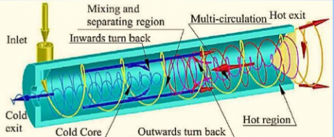
The vortex tube is a device that has a simple geometry, without any moving or complicated parts that separates a pressurized gas into hot and cold streams. A schematic drawing of a typical vortex tube and its proceeds is shown in Fig. 1. A vortex tube includes different parts such as: one or more inlet nozzles, a vortex-chamber, a cold end orifice, a control valve that is located at hot end and finally a working tube. When pressured gas is injected into the vortex-chamber tangentially via the nozzle intakes, a strong rotational flow field is created. When the gas swirls to the center of the vortex-chamber it is expanded and cooled. After occurrence of the energy separation procedure in the vortex tube the pressured inlet gas stream was separated into two different gas streams including cold and hot exit gases. The “cold exit or cold orifice” is located at near the inlet nozzle and at the other side of the working tube there is a changeable stream restriction part namely the conical control valve which determines the mass flow rate of hot exit. As seen in Fig. 1, a percent of the compressed gas escapes through the conical valve at the end of the tube as hot stream and the remaining gas returns in an inner swirl flow and leaves through the cold exit orifice. Opening the hot control valve reduces the cold air flow and closing the hot valve increases the cold mass flow rate. The vortex tube air separator is discovered (for the first time) by a French researcher. In this article, we utilize the numerical models to explain the details of the separation process inside the air separator.
Figure 1. A schematic drawing of Ranque-Hilsch vortex tube
Researches on the vortex tube air separators has a long history, however, we explain a brief list of important works as follow: The heat and mass transfer between the cold and hot cores (inside the vortex tube) is analyzed by Rafiee and Sadeghiazad [1]. The capabilities of different turbulence models (the RSM, LES, k–ω, k–ɛ and SST k–ω) for predicting the flow structures within the air separator were examined by Baghdad et al. [2] and Rafiee and Sadeghiazad [3]. Guo et al. [4] studied the thermal performance of vortex tubes with small diameters. Pourmahmoud et al. [5] analyzed the effect of shell heat transfer on vortex tube performance. Pourmahmoud et al. [6] determined the optimum value for the length of vortex tube. Some variations in the temperature drops are seen when a bended main tube is used in the structure of the air separator. These variations are reported in comparison with the air separator equipped with the straight main tube (Rafiee et al. [6]. The effect of divergent main tube has been investigated by Rahimi et.al [7] and the optimum angle for the divergent main tube has been achieved numerically. Some factors regarding the vortex tube structure (the inlet of slots, the ratio of slots, the hot and cold exit area, the rounding off edge radius, the internal radius of main tube and the convergent slots) were optimized by Rafiee et al. [8], Rafiee and sadeghiazad [9] and Pourmahmoud et al. [10]. Some refrigerant gases (R728, R32, R134a, R161, R744, and R22) have been examined in the vortex tube air separator and the thermal performance of air separator has been studied and the best refrigerant gas has been determined (Pourmahmoud et al. [11] and Han et al. [12]). Rafiee and Sadeghiazad [13] analyzed the effect of different boundary conditions (pressure outlet and pressure far field) at the outlets and different working gases on the energy separation inside a vortex tube. Rafiee and Sadeghiazad [14 and 15] managed some experimental setups to optimize the control valve structural parameters such as the conical angle and the cone length and proved that there are some optimized values which lead to the best thermal capability. The impact of a new shape of the hot tube (the convergent main tube) is experimentally tested by Rafiee et al. [16]. Their results stated that there is an optimized angle for the convergent main tube to produce the best cooling capacity. Rafiee and Sadeghiazad [17] proposed a new energy explanation to analyze the thermal distribution and the exergy density inside the air separator applying the measured flow factors along the hot tube. The thermophysical parameters inside the vortex tube are comprehensively reported by Rafiee and Rahimi [18]. A valuable work was done to analyze the isotope separation using vortex tubes by Lorenzini et al. [19]. In the presented work with assuming the advantages of using different radius of vortex chamber on the energy separation process and its considerable role on the creation of maximum cooling capacity of machine, the optimum radius is elected. This research believes that choosing an appropriate design of nozzle is the one of important physical parameters for obtaining the highest refrigeration efficiency. So far numerical investigations towards optimization of vortex chamber radius have not been done.
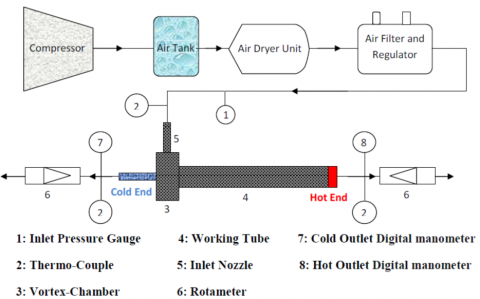
The schematic diagram of the experimental setup is shown in Fig. 2.
Figure. 2. Schematic diagram of the experimental setup.
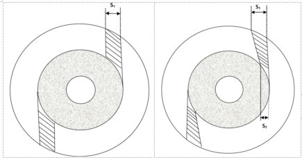
Compressed air is processed through the air tank and regulator, and then guided tangentially inside the vortex tube via a nozzle. The stagnation temperature of inlet air before the nozzle inlet of vortex tube is regulated to 294.2K (±0.5 K). The air stream inside the tube consequently creates a quick swirling vortex field; meanwhile it is separated into two streams including; cold and hot streams. The mass flow rate of the cold flow at cold exhaust is measured by using rotameter (6). The temperatures of the streams at the inlet, cold and hot exits are measured with thermocouples and the pressures of these streams are controlled by pressure transducers. The vortex tube is designed with constant parameters i.e. internal diameter of working tube D = 18mm, diameter of cold exit dc =D/2=9 mm and the length of working tube L=250 mm. The schematic form of convergent nozzles is shown in Fig. 3. The convergence ratio (K=S1 /S2) of nozzle intakes is variable in range from 1 to 2.85. In the straight nozzle K=1 and for convergent nozzles K>1.
Figure 3. A schematic form of convergent nozzles used in tests
In the all of tested vortex tubes S1=2.85mm, meanwhile to understand the effect of convergent nozzle on the temperature reduction, five different value for S2 have been taken, i.e. S2= 2.85, 2.4, 2.2, 1.5and 1mm are experimented by using a constant working tube with length of L = 250 mm.
The compressible turbulent and highly rotating flow inside the vortex tube is assumed to be three-dimensional, steady state and employs the standard k-ε turbulence model on the basis of the finite volume method. The RNG k-ε turbulence model and more advanced turbulence models such as the Reynolds stress equations were also investigated. Consequently, the governing equations are arranged by the conservation of mass, momentum and energy equations, which are given by:
The equation for conservation of mass, or continuity equation, can be indicated as follows:
The equation for conservation of mass, or continuity equation, can be indicated as follows:
$\frac{\partial \rho}{\partial t}+\nabla \cdot(\rho \stackrel{\mathrm{r}}{v})=S_{m}$ (1)
Momentum equation:The flow field in this investigation has been assumed ‘steady state’ and term Sm is the mass added to continuous domain from other domains.
$\frac{\partial}{\partial_{X_{j}}}\left(\rho_{\mathcal{U}_{i} \mathcal{U}_{j}}\right)=-\frac{\partial p}{\partial_{\mathcal{X}_{i}}}+\frac{\partial}{\partial x_{j}}$$\left[\mu\left(\frac{\partial u_{i}}{\partial x_{j}}+\frac{\partial u_{j}}{\partial x_{i}}-\frac{2}{3} \delta_{i j} \frac{\partial u_{k}}{\partial x_{k}}\right)\right]$$+\frac{\partial}{\partial x_{j}}\left(-\overline{\rho} \overline{u}_{i}^{\prime} \vec{u}_{j}^{\prime}\right)$ (2)
Energy equation:
$\frac{\partial}{\partial x_{i}}\left[\mathcal{U}_{i} \rho\left(h+\frac{1}{2} \boldsymbol{u}_{j} \boldsymbol{u}_{j}\right)\right]$$=\frac{\partial}{\partial_{\mathcal{X}_{j}}}\left[k_{e f f} \frac{\partial T}{\partial_{\mathcal{X}_{j}}}+\mathcal{U}_{i}\left(\tau_{i j}\right)_{e f f}\right]$, (3)
Since we determined the working fluid is an ideal gas, then the compressibility effect must be considered as below:
$p=\rho R T$ (4)
The turbulence kinetic energy (k) and the rate of dissipation (ε) are obtained from the following equations:
$\frac{\partial}{\partial t}(\rho k)+\frac{\partial}{\partial x_{i}}\left(\rho k u_{i}\right)=\frac{\partial}{\partial x_{j}}\left[\left(\mu+\frac{\mu_{t}}{\sigma_{k}}\right) \frac{\partial k}{\partial x_{j}}\right]+G_{k}+G_{b}-\rho \varepsilon-Y_{M}$ (5)
$\frac{\partial}{\partial t}(\rho \varepsilon)+\frac{\partial}{\partial x_{i}}\left(\rho \varepsilon u_{i}\right)=\frac{\partial}{\partial x_{j}}\left[\left(\mu+\frac{\mu_{t}}{\sigma_{\mathcal{E}}}\right) \frac{\partial \varepsilon}{\partial x_{j}}\right]+C_{1 \varepsilon} \frac{\varepsilon}{k}\left(G_{k}+C_{3 \varepsilon} G_{b}\right)-C_{2 \varepsilon} \rho \frac{\varepsilon^{2}}{k}$ (6)
In these equations, Gk, Gb, andYM represent the generation of turbulence kinetic energy due to the mean velocity gradients, the generation of turbulence kinetic energy due to buoyancy and the contribution of the fluctuating dilatation in compressible turbulence to the overall dissipation rate, respectively. C1ε and C2εare constants. σk and σε are the turbulent Prandtl numbers for k and ε also. The turbulent (or eddy) viscosity, µt, is computed as follows:
$\mu_{t}=\rho C_{\mu} \frac{k^{2}}{\varepsilon}$ (7)
where, Cμ is a constant. The model constants C1ε, C2ε, Cμ, σk and σε have the following default values: C1ε = 1.44, C2ε = 1.92, Cμ = 0.09, σk = 1.0, σε = 1.3.
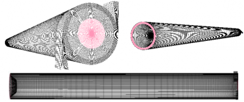
Figure 4. 3D CFD model of vortex tube
The 3D CFD mesh grid is shown in Fig. 5. In this model, a regular organized mesh grid has been used. All radial lines of this model of meshing have been connected to the centerline and the circuit lines have been regularly designed from wall to the centerline. So, the volume units that have been created in this model are regular cubic volumes. This meshing system helps the computations to be operated faster than the irregular meshing, and the procedure of computations have been done more precisely. Boundary conditions for this study have been indicated in this part. The inlet is modeled as pressure inlet. The inlet stagnation temperature and the pressure inlet are fixed to 294.2 K and 2.5 bar respectively, according to the experimental conditions. A no-slip boundary condition is used on all walls of the system. The cold and hot exits boundary condition can be considered as the pressure-far-field. A vortex tube usually works under the ambient conditions and for changes in the cold mass fraction one needs to change the area of hot exit. The computations in this study utilize a pressure correction based iterative SIMPLE algorithm for discretising the convective transport terms. A compressible form of the Navier-Stokes equation along with the standard k-ε model by the second order upwind for momentum, turbulence and energy equations have been used to simulate the phenomenon of flow pattern and temperature separation in a vortex tube with 2 convergent inlet nozzles operating under condition of using different geometries of nozzle by using the FLUENTTM software package. The 3D CFD analysis has been performed for different average unit cell volumes in vortex tube as a computational domain. This is for the reason that removing probable errors arising due to grid coarseness. Therefore, first the grid independence study was carried out for α=0.24.
As seen in Fig. 6, at this cold mass fraction the vortex tube achieves a minimum outlet cold gas temperature. Consequently, in most of the evaluations we used α=0.24 as a special value for cold mass fraction. The variation of cold exit temperature difference as the main parameters is shown in Fig. 5 for different unit cell volumes. Not much major advantage can be seen in reducing of the unit cell volume size below 0.026 mm3; which corresponds to 1148000 cells.
Figure 5. Grid size independence study on cold temperature difference at different average unit cell volume
The cold mass fraction and the cold temperature difference between inlet flow and cold stream are two effective parameters to expose the operational characteristics for the vortex tube refrigerator. Cold temperature difference (or temperature reduction) shows the cryogenic performance and can be defined as below:
$\Delta T_{c}=T_{i}-T_{c}$ (8)
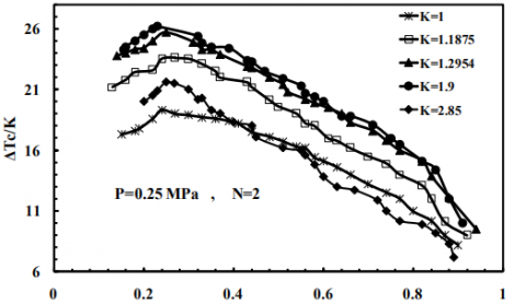
The experimental results obtained from the tests, which involve the effect of convergent nozzle, number of convergent nozzle intakes and the pressure at the inlets on the vortex tube performance, are presented in this section. Typical ratios mentioned below have been employed to investigate the performance of the vortex tube refrigerator with a convergent nozzle. To expose the effect of convergent nozzles on the temperature reduction (Fig. 6), five different convergence ratios i.e. K=1, 1.1875, 1.2954, 1.9 and 2.85 are tested by using a constant working tube with length of L= 250 mm. The K=1 represent the counter-flow vortex tube with a straight nozzle. The number of nozzle intake is N= 2.
Figure 6. Influence of the convergence ratio of nozzle on the cold temperature difference
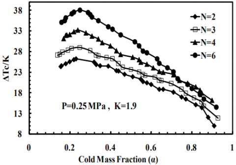
Figure 7. Effect of the number of convergent nozzle on the cold temperature difference.
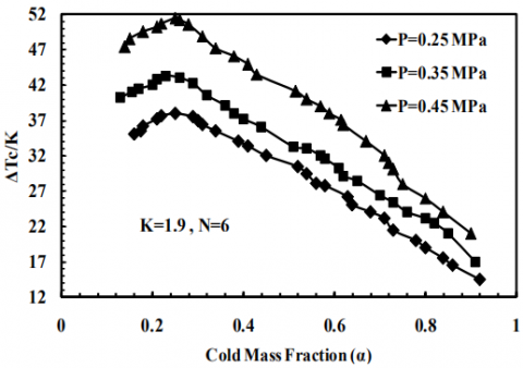
Figure 8. Cold temperature difference as functions of the cold mass fraction with various pressures
Fig. 6 shows the variation in ΔTc for convergence ratios at different cold mass fractions with inlet pressure of 0.25 MPa. These models were tested and the thermal performance was analyzed while the cold mass fraction was variable. The results indicate that there is optimal value for K to obtain the highest refrigeration efficiency.
According to the results, the cold temperature difference increased when we take into account the effect of convergence ratio in the range of 1-1.2954. The effect of the convergent nozzle intake number on the vortex tubes performance has not been reported yet. On basis of the conclusions for straight nozzles, some reported that increasing the number of nozzles can produce a strong swirling flow field inside the vortex tube and consequently help to improve the temperature separation procedure whereas, some researchers [15] said that the vortex tubes performance decreases with the increase of the nozzles number due to the development of the turbulent flow filed. To indicate the effect of the intake number on the cryogenic capacity of vortex tubes with convergent nozzles, N =2, 3, 4 and 6 nozzles are investigated at inlet pressure of 0.25 MPa with constant parameters K=1.9 and L =250 mm. Fig. 7 indicates the effect of N = 2, 3, 4 and 6 nozzles on the ΔTc of the vortex tube refrigerator with convergent nozzles. The highest ΔTc is 26.52 K for K=2.22 at a cold mass fraction of about 0.24, higher than that of K=1 around 37.4% at the same cold flow fraction. The contours of total temperature of optimum model for the inlet gas temperature 294.2 K and cold mass fraction 0.24 are shown in Fig. 9.
The influence of the convergent nozzles, the inlet pressure at convergent nozzle intakes and the number of convergent nozzle intake on the cryogenic performance was studied experimentally and numerically for a vortex tube and the major conclusions can be summarized as below. The vortex tube performance can be improved by employing convergent nozzles and the tests illustrated that we have an optimum model between K=1 and K=2.85. Preliminary tests (before the optimization) show that the convergence ratio (K) should be small and not more than 1.9 under our experimental tests so there is an optimum convergence ratio of nozzle to achieve the highest possible refrigeration performance.
Figure 9. Contours of total temperature of the optimum model
The preliminary experimental results indicate that the 1.9 convergent ratio yields the highest cold temperature reduction, which exceeds the straight one by about 35.7%. In fact the optimal model before the optimization was K=1.9. The influence of nozzle inlets on the cryogenic performance relies on the cold mass fraction. Increasing the number of convergent nozzles leads to a severe sensitivity of ΔTc with the variation of the cold mass fraction and achieves the highest possible cold temperature drop ΔTc at lower cold mass fraction as well. The ratio of actual cold temperature difference to the maximum temperature reduction, ΔTc / (ΔTc)max, for the vortex tube with convergent nozzles can be presented as a function of the cold mass fraction. The purpose of this investigation was to create a 3D CFD model of a simple vortex tube for employ as a design tool in optimizing vortex tube parameters and geometries. The model was developed using a three-dimensional (3D) steady model that utilized the standard k-epsilon turbulence equations. The comparison between the 3D CFD results and the measured experimental data yielded promising results relative to the model’s capability to predict the energy separation. Deviation of the predicted and measured values for the cold temperature difference is less than or equal to 3.82% (at cold mass fraction of 0.24). Twenty-nine CFD models have been created between K=1.2954 and K=2.85 to optimize the convergence ratio. Experimental and numerical results show that the best candidate for convergence ratio is K=2.22 (after optimization) which creates the cold temperature difference equal to 27.86K and 26.52K respectively. This result show that this optimization improves the vortex tube performance around 37.4%. Studying and optimizing the geometrical parameters computationally is far less time consuming and costly than testing design variations. In this field, the 3D model is useful as a time saving and cost-effective tool for designing and optimizing vortex tubes.
[1] Rafiee S.E., Sadeghiazad M.M. (2016). Heat and mass transfer between cold and hot vortex cores inside Ranque-Hilsch vortex tube-optimization of hot tube length, International Journal of Heat and Technology, Vol. 34, No. 1, pp. 31-38. DOI: 10.18280/ijht.340105
[2] Baghdad M., Ouadha A., Imine O., Addad Y. (2011). Numerical study of energy separation in a vortex tube with different RANS models, Int. J. Thermal Sciences, Vol. 50, No. 12, pp. 2377-2385. DOI: 10.1016/j.ijthermalsci.2011.07.011
[3] Rafiee S.E., Sadeghiazad M.M. (2016). Three-dimensional computational prediction of vortex separation phenomenon inside Ranque-Hilsch vortex tube, Aviation, Vol. 20, No. 1, pp. 21-31 DOI: 10.3846/16487788.2016.1139814
[4] Guo Q., Qi X., Wei Z., Guo P., Sun P. (2016). 3D numerical simulation and analysis of refrigeration performance of the small diameter vortex tube, International Journal of Heat and Technology, Vol. 34, No. 3, pp. 513-520. DOI: 10.18280/ijht.340324
[5] Pourmahmoud N., Abbaszadeh M., Rashidzadeh M. (2016). Numerical simulation of effect of shell heat Transfer on the vortex tube performance, International Journal of Heat and Technology, Vol. 34, No. 2, pp. 293-301. DOI: 10.18280/ijht.340220
[6] Pourmahmoud N., Esmaily R., Hassanzadeh A. (2015). CFD investigation of vortex tube length effect as a designing criterion, International Journal of Heat and Technology, Vol. 33, No. 1, pp. 129-136. DOI: 10.18280/ijht.330118
[7] Rahimi M., Rafiee S.E., Pourmahmoud N. (2013). Numerical investigation of the effect of divergent hot tube on the energy separation in a vortex tube, International Journal of Heat and Technology, Vol. 31, No. 2, pp. 17-26.
[8] Rafiee S.E., Rahimi M., Pourmahmoud N. (2013). Three-dimensional numerical investigation on a commercial vortex tube based on an experimental Model - Part I: optimization of the working tube radius, International Journal of Heat and Technology, Vol. 31, No. 1, pp. 49-56.
[9] Rafiee S.E., Sadeghiazad M.M. (2015). 3D numerical analysis on the effect of rounding off edge radius on thermal separation inside a vortex tube, International Journal of Heat and Technology, Vol. 33, No. 1, pp. 83-90.
[10] Pourmahmoud N., Hasanzadeh A., Rafiee S.E., Rahimi M. (2012). Three-dimensional numerical investigation of effect of convergent nozzles on the energy separation in a vortex tube, International Journal of Heat and Technology, Vol. 30, No. 2, pp. 133-140.
[11] Pourmahmoud N., Rafiee S.E., Rahimi M., Hasanzadeh A. (2013). Numerical energy separation analysis on the commercial Ranque-Hilsch vortex tube on basis of application of different gases, Scientia Iranica., Vol. 20, No. 5, pp. 1528-1537.
[12] Han X., Li N., Wu K., Wang Z., Tang L., Chen G., Xu X. (2013). The influence of working gas characteristics on energy separation of vortex tube, Applied Thermal Engineering, Vol. 61, No. 2, pp. 171-177. DOI: 10.1016/j.applthermaleng.2013.07.027
[13] Rafiee S.E., Sadeghiazad M.M., (2016). Three-dimensional numerical investigation of the separation process inside vortex tube using different operating conditions, Journal of Marine Science and Application, pp. 1-10. DOI: 10.1007/s11804-016-1348-8
[14] Rafiee S.E., Sadeghiazad M.M. (2014). Effect of conical. valve angle on cold-exit temperature of vortex tube, Journal of Thermophysics and Heat Transfer, Vol. 28, pp. 785-794. DOI: 10.2514/1.T4376
[15] Rafiee S.E., Sadeghiazad M.M. (2014). Three-dimensional and experimental investigation on the effect of cone length of throttle valve on thermal performance of a vortex tube using k–ɛ turbulence model, Applied Thermal Engineering, Vol. 66, No. 1-2, pp. 65-74. DOI: 10.1016/j.applthermaleng.2014.01.073
[16] Rafiee S.E., Sadeghiazad M.M., Mostafavinia N. (2013). Experimental and numerical investigation on effect of convergent angle and cold orifice diameter on thermal performance of convergent vortex tube, J. Thermal Sci. Eng. Appl, Vol. 7, No. 4. DOI: 10.1115/1.4030639
[17] Rafiee S.E., Sadeghiazad M.M. (2014). 3D CFD exergy analysis of the performance of a counter flow vortex tube, International Journal of Heat and Technology, Vol. 32, No. 1-2, pp. 71-77.
[18] Rafiee S.E., Rahimi M. (2014). Three-dimensional simulation of fluid flow and energy separation inside a vortex tube, Journal of Thermophysics and Heat Transfer, Vol. 28, pp. 87-99. DOI: 10.2514/1.T4198
[19] Lorenzini E., Spiga M. (1982). Aspetti fluidodinamici della separazione isotopica mediante tubi a vortice di Hilsch Ingegneria, No. 5-6, pp. 121-126.