OPEN ACCESS
The objective of the present work is to reduce the light-off time of the catalyst and at the same time reduce the thermal degradation and ageing of the catalyst to the minimum possible extent by adopting an approach with Dynamic Catalytic Converter System (DCCS). In this approach, the catalytic converter is kept very close to the exhaust manifold during cold start of the vehicle and once it attains the light-off temperature the converter is moved to a far away position as any other conventional converter thereby reducing damages caused due to overheating. The emission tests were conducted in a four-cylinder spark ignition engine with DCCS at different positions from the engine outlet manifold and also with pre-catalysts of 40% volume of the main catalytic converter. It was established that considerable reduction in the light off time was achieved by using DCCS and light-off time was further reduced by using pre-catalysts as compared to the conventional catalytic converter. The CO light-off time of main catalytic converter reduced 60% with DCCS with PC (40%) and the corresponding reduction for HC light-off time is 57% compared to main catalytic converter without DCCS.
Dynamic Catalytic Converter, Cold Start Emission, Spark Ignition Engine, Light off Temperature
Air pollution generated from automobile sources is of late, a serious problem to humankind. Emission in internal combustion engines affects the quality of air leading to global warming and degeneration of human health [1]. Vehicles emit the harmful exhaust emissions within the first 2-3 minutes after engine cranking following a cold-start [2]. A cold start is defined as an engine start following a 12 to 36 hours continuous vehicle soak in a constant temperature environment of 20°C to 30°C [3]. Two factors contribute to the high emission at cold start. First, the catalyst does not begin to oxidize HC and CO until it reaches an effective operating temperature, called light off temperature. Second, most engines generally run with a rich mixture during warm-up [4]. The oxidation reaction cannot begin without adequate supply of oxygen [5].
During the cold start, rich mixture gets supplied to the engine and oxygen supply is insufficient for completing full combustion of hydrocarbon [6]. Due to incomplete combustion, potentially harmful products like un-burnt hydrocarbons and carbon monoxides are produced [7].
Catalytic converters get activated and start reducing the emissions only after they reach the light-off temperature, which happens normally around 250-300°C [8]. The time period at which the catalyst becomes active is referred to as light-off time. The catalyst is said to be active for a particular volume emission when the conversion efficiency reaches 50%. Till the catalyst attains light-off, the harmful pollutants go out of the tail pipe untreated and such emission is referred to as cold start emission. Nearly 60 to 80% of the engine out emission occurs in the cold start during the first 300 seconds [9].
At low temperatures, the efficiency of conventional catalytic converters declines very steeply. During cold start and warming period, the converter efficiency is very close to zero [10]. To reduce the cold start emission, the light-off temperature has to be attained rapidly. There are active and passive methods for rapid light-off [11]. The active methods include electrically heated metal catalyst, catalyzed fuel burner, exhaust gas ignition with secondary air injection. Passive methods include close coupled catalyst (CCC), use of pre-catalysts, air gap insulation, phase change material and variable conductance insulation.
Preheating is used in the catalytic converter to achieve rapid light off temperature [12][13]. Using Phase Change material (PCM) the excess heat generated during the running of the engine is being stored and utilized during cold start period to keep the catalyst above the light-off temperature over a long period of time [14][15]. Using air gap and insulating material over the catalyst outer surface, it retains the temperature of the catalyst even hours after the engine is stopped [16]. Electrically heated catalyst using an external heater helps the catalyst to reach light off before starting the engine. The exhaust wall pipe is made a single or double wall in order to reduce the heat loss of exhaust gases which contributes to the heating of the main catalyst faster. The pre-catalyst will attain the light off much earlier and hence reduces the cold start emission [17]. The catalyst is close coupled with the exhaust manifold and hence exhaust gases take much lesser time to light off the catalyst [18]. The secondary air injection at exhaust manifold aids oxidation of CO and HC and exothermic oxidation reaction increases the temperature of exhaust gas, resulting in fast light-off of catalyst [19]. Close coupled catalyst is a good solution for reducing the light off time [20]. However, due to the close proximity of the converter from the engine exhaust manifold, it is subjected to a high temperature of around 800°C throughout the operation of the engine. This causes thermal degradation of the catalyst and accelerates the aging.
The objective of the present work is to reduce the light-off time of the catalyst to the minimum possible extent. Dynamic catalytic convertor system (DCCS) is suggested to achieve rapid light off and at the same time to overcome the damages caused to the catalyst due to the proximity of the catalyst. In this approach, the catalyst is kept very close to the exhaust manifold during cold start of the vehicle and once it attains the light-off temperature the same catalyst is moved to a far away position as any other conventional catalyst thereby reducing damages caused due to overheating [21][22]. The experiments were also conducted with pre-catalysts of 40% volume of the main catalytic converter to reduce the light-off time further.
A Dynamic Catalytic Converter System (DCCS) consists of a number of pipes of increasing diameter which can be stacked one inside the other so that the length of the pipe can be extended or shortened. One end of the dynamic pipe is attached to the exhaust manifold of the engine and the other end is attached to the catalytic converter. In the present work, the dynamic pipe consists of 6 pipes each measuring 150mm length. The maximum diameter of the pipe being 60mm and the succeeding pipes have the diameters 50 mm,40mm,30mm, 25mm and 20mm respectively. To prevent the leakage of exhaust gases rubber sealing is provided in between the pipes. The schematic diagram of DCCS is shown in Figure 1. The photographic view of the experimental setup is shown in Figure 2. The CO and HC emission values are measured using AVL DIGAS analyzer. The temperature of exhaust gas and catalyst are measured using a K-type thermocouple and stored using a data logger.
Figure 1. Schematic diagram of DCCS
Figure 2. Photographic view of experimental setup with DCCS
The DCCS is connected to the lead screw arrangement coupled to the DC motor. When the engine is started in the cold condition the catalytic converter will be at a minimum distance of 150mm from the exhaust manifold. The thermocouple senses the temperature continuously and once catalyst reaches light-off, ESC actuates the DC motor to move the catalytic converter to the next position. At each position when the catalyst attains light-off temperature it moves to the next position and reaches the maximum distance of 900mm from the exhaust manifold. The catalyst will be positioned at the maximum distance till the engine is stopped. The DCCS at the maximum position is equivalent to the conventional catalytic converter. Thus, the catalyst is safe under thermal degradation and prevented from early aging. The emission tests were conducted on 4-cylinder petrol engine, the specification of the engine is given in Table 1.
Table.1 Engine specifications
|
Make |
Izusu |
|
Type |
Inline Four, SOHC with MPFI |
|
Fuel |
Petrol |
|
Displacement Volume |
1,817 cc |
|
Bore / Stroke |
84x 82 cc |
|
Compression Ratio |
8.5: 1 |
|
Power |
10 HP @2000 rpm |
|
Cooling |
Water cooled |
|
Exhaust Pipe Diameter |
Φ20 |
2.1 Test conditions
The investigation under study is cold start emission, the emission values recorded during the first few minutes only. Following are the test conditions:
1.DCCS at different positions of the catalyst (150mm, 300mm, 450mm, 600mm,750mm and 900mm from exhaust manifold)
2.DCCS with Pre-catalysts (PC) – Pre-catalyst 40% volume of the main catalytic converter.
All the above tests were conducted at full load conditions at an engine speed of 2000 rpm. Following parameters are measured in the present work.
Emission test has been conducted with DCCS at different positions of the catalyst and at full load conditions and the test results are compared. The tests were conducted at an ambient temperature of 36°C. The different positions of DCCS are as given below:
In DCCS, Position 1 is equivalent to close coupled catalyst and Position 6 is equivalent to the conventional main catalyst. Light-off temperature with DCCS was found by connecting the DCCS to the exhaust manifold of the engine. The engine is run at 2000 rpm and the CO and HC emission values were recorded.
Figure 3 shows the variation of CO and HC conversion efficiency of DCCS with temperature. It is found that DCCS attains CO light-off at a temperature of 286°C and HC light-off at a temperature of 323°C.
Figure 3. Variation of conversion efficiency of DCCS with temperature
The reason being, HC gets oxidized at a higher temperature and requires more heat to burn compared to CO. Also, oxidation of carbon monoxide to carbon dioxide is a single step reaction and requires less activation energy for the conversion, whereas hydrocarbon requires more activation energy.
3.1 Emission characteristics and light-off time of DCCS
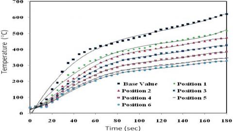
The different positions with DCCS (Position1 to Position 6) are at 150mm to 900mm from the exhaust manifold with an increment of 15 cm from one position to other. Figure 4 shows the variation of temperature with time for the telescopic catalytic converter. At this condition, the temperature of the exhaust gas at exhaust manifold increased from the ambient temperature (36°C) to 622°C in 180 seconds referred as Base value. During the same time period, the temperature of the catalyst at Position 1 to Position 6 is observed to be 516°C, 474°C, 427°C, 384°C, 346°C and 328°C respectively. At Position 1 CO light-off temperature is attained at 44 seconds and HC light-off temperature attained at 52 seconds. At Position 6 CO light-off temperature is attained in 109 seconds and HC light-off temperature in 117 seconds.
Figure 4. Variation of temperature DCCS with time
Figure 5 shows the variation of CO conversion efficiency with time. It is observed that at position 1, the catalyst reached CO-light-off in 44seconds, at position 2 in 54seconds, at position 3 in 68seconds, at position 4 in 79seconds, at position 5 in 97seconds and at position 6 in 109seconds.
Figure 5. Variation of CO conversion efficiency with time
Figure 6. Variation of HC conversion efficiency with time
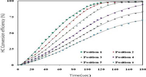
Figure 6 shows the variation of HC conversion efficiency of the catalyst with time and it is observed that at position 1 HC-light off occurred at 52 seconds, at position 2 at 59 seconds, at position 3 at 72seconds, at position4 at 86 seconds, at position 5 at 101seconds, at position 6 at 117seconds. It was observed that light-off time of CO is less than that of HC at all positions of the catalyst.
For instance, at Position 1 light-off time for CO is 44 seconds and for HC it is 52 seconds, the reason being, HC gets oxidized at a higher temperature and requires more heat to burn as compared to CO. Also, oxidation of carbon monoxide to carbon dioxide is a single step reaction and requires less activation energy for the conversion, whereas hydrocarbon requires more activation energy.
3.2 Emission characteristics and light-off time of DCCS with Pre-Catalyst (PC) with 40% volume of main catalytic converter
Figure 7. Schematic diagram of DCCS with 40% pre-catalyst
Pre-converter, 40% volume of the main catalytic converter is connected to the exhaust manifold and DCCS is connected to PC at different positions. The different positions of DCCS (Position1 to Position 6) are at 150mm to 900mm from the PC (40%) with an increment of 150mm from one position to the next position. i.e. at Position 1, the DCCS is at 150mm from PC, at Position 2 the DCCS is at 300mm from PC, at Position 3 the DCCS is at 450mm from PC and so on. Emission test was conducted at full load conditions and the test results are compared. DCCS with PC (40%) is shown in Figure 7.
Figure 8. Variation of temperature of DCCS with pre-catalyst (40%)
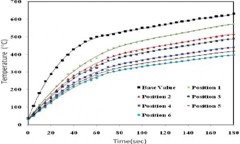
Figure 8 shows the variation of exhaust gas temperature and temperature of DCCS with PC (40%) at different positions with time. At this condition, the temperature of the exhaust gas at exhaust manifold increased from the ambient temperature (36°C) to 630°C in 180 seconds referred as Base value. During the same time period, the temperature of the catalyst at Position 1 to Position 6 is observed to be 573°C, 516°C, 490°C, 441°C, 419°C and 398°C respectively. It is observed that DCCS without a pre-catalyst at full load condition at Position 1 attained a temperature of 516°C in 180 seconds, whereas the DCCS with PC (40%) attained a temperature of 573°C in the same time. It is found that there is 10% increase in temperature of the DCCS due to the presence of PC (40%). The increase in temperature is due to the exothermic reaction of the exhaust gas when it passes through the PC, resulting in heating the DCCS at a faster rate.
Figure 9. Variation of CO conversion efficiency with time of DCCS with pre-catalyst (40%)
Figure 9 shows the variation of CO conversion efficiency with time for PC (40%) at full load condition. It is observed that at Position1 the light off occurred in 35seconds, at Position 2 in 39 seconds, at Position 3 in 45seconds, at Position 4 in 53 seconds, at Position 5 in 60 seconds and at Position 6 in 64 seconds. It has been observed that the DCCS with PC (40%) reached CO- light-off at Position 1 in 35 seconds; whereas DCCS without PC at the same test condition reached light-off in 44seconds. It is found that there is 22% reduction in light-off time by using the PC (40%) when compared to DCCS without PC. It is also observed that after 100 seconds all six positions of DCCS, CO conversion is almost same up to 180 seconds, and is not included in Figure 9.
Figure 10. Variation of HC conversion efficiency with time of DCCS with pre-catalyst (40%)
Figure 10 shows the variation of HC conversion efficiency with time for DCCS with PC (40%vol) at full load condition. It is observed that at Position1 the light off occurred in 40 seconds, at Position2 in 44 seconds, at Position3 in 50seconds, at Position 4 in 54 seconds, at Position 5 in 60 seconds and at Position 6 in 70 seconds. It has been observed that light-off time of CO is less than that of HC at a given position and load. For instance, at position 1 light-off time for CO was 35seconds and for HC it was 40 seconds. Thus, it is observed that CO conversion efficiency is more than HC conversion efficiency at a given point of time. It is also observed that after 120 seconds all six positions of DCCS HC conversion is almost same up to 180 seconds, and is not included in Figure 10.
From the above, various fast light-off techniques used in the investigation, the following conclusions have been drawn:
The control of exhaust emissions from spark ignition engines is primarily based on the temperature of the after-treatment devices, particularly during cold start. The test results showed that the CO light-off time of main catalytic converter reduced 60% with DCCS with PC (40%) and the corresponding reduction for HC light-off are 57% compared to main catalytic converter without DCCS. It was established that considerable reduction in the light-off time was achieved by using DCCS with 40% pre-catalyst.
DCCS Dynamic catalytic converter system
HC Hydrocarbon
CO Carbon monoxide
CCC Closed coupled catalyst
PCM Phase change material
SOHC Single overhead cam
MPFI Multi-point fuel injection
DC Direct current
PC Pre-catalyst
[1] Edelberg K., Pan S., Hedrick J.K. (2013). A discrete-time sliding mode formulation for automotive cold-start emission control, Proceedings of the IEEE Conference on Decision and Control, pp. 6818–6823. DOI: 10.1109/CDC.2013.6760969
[2] Dardiotis C., Martini G., Marotta A., Manfredi U. (2013). Low-temperature cold-start gaseous emissions of late technology passenger cars, Applied Energy, Vol. 111, pp. 468–78. DOI: 10.1016/j.apenergy.2013.04.093
[3] Chen R.H., Chiang L.B., Chen C.N., Lin T.H. (2011). Cold-start emissions of an SI engine using ethanol-gasoline blended fuel, Applied Thermal Engineering, Vol. 31, pp. 1463–1467. DOI: 10.1016/j.applthermaleng.2011.01.021
[4] Sendilvelan S., Sundarraj C. (2016). Performance and emission study on a dual fuel engine with modified gas inlet, International Journal of Heat and Technnology, Vol. 34, pp. 545–550. DOI: 10.18280/ijht.340328
[5] Arapatsakos C., Karkanis A., Anastasiadou C., Engineering M. (2015). The load and the gas emission, Measurement of Outboard, Vol. 33, pp. 221–228.
[6] Sendilvelan S., Jeyachandran K., Bhaskar K. (2001). Pollution studies on gasoline engine with electrically heated catalyst, American Society of Mechanical Engineers, Internal Combustion Engine Division (Publication) ICE, Vol. 36, pp. 95-99.
[7] Nithyanandan N., Sendilvelan S., Bhaskar K., Balaji N., Mohanamurugan S. (2010). Exposed area influence for light off of catalyst to reducing hc/co emission from automobile SI engine exhaust by using low mass electrically heated metal catalyst, International Journal of Applied Engineering Research, Vol. 5, pp. 441–448.
[8] Clairotte M., Adam T.W., Zardini A.A., Manfredi U., Martini G., Krasenbrink A., et al. (2013). Effects of low temperature on the cold start gaseous emissions from light duty vehicles fuelled by ethanol-blended gasoline, Applied Energy, Vol. 102, pp. 44–54. DOI: 10.1016/j.apenergy.2012.08.010
[9] Weilenmann M., Favez J.Y., Alvarez R. (2009). Cold-start emissions of modern passenger cars at different low ambient temperatures and their evolution over vehicle legislation categories, Atmospheric Environment, Vol. 43, pp. 2419–2429. DOI: 10.1016/j.atmosenv.2009.02.005
[10] Roberts A., Brooks R., Shipway P. (2014). Internal combustion engine cold-start efficiency: a review of the problem, causes and potential solutions, Energy Conversion and Management, Vol. 82, pp. 327–350. DOI: 10.1016/j.enconman.2014.03.002
[11] Pace L., Presti M. (2011). An alternative way to reduce fuel consumption during cold start: the electrically heated catalyst, SAE Technical Papers, DOI: 10.4271/2011-24-0178
[12] Ramanathan K., Balakotaiah V., West D.H. (2003). Light-off criterion and transient analysis of catalytic monoliths, Chemical Engineering Science, Vol. 58, pp. 1381–1405. DOI: 10.1016/S0009-2509(02)00679-6
[13] Ramanathan K., West D.H., Balakotaiah V. (2004). Optimal design of catalytic converters for minimizing cold-start emissions, Catalysis Today, Vol. 98, pp. 357–373. DOI: 10.1016/j.cattod.2004.08.003
[14] Rostamizadeh M., Khanlarkhani M., Mojtaba S.S. (2012). Simulation of energy storage system with phase change material (PCM), Energy and Buildings, Vol. 49, pp. 419–422. DOI: 10.1016/j.enbuild.2012.02.037
[15] Kim K., Choi K., Kim Y., Lee K., Lee K. (2009). Feasibility study on a novel cooling technique using a phase change material in an automotive engine, Energy, Vol. 35, pp. 478–484. DOI: 10.1016/j.energy.2009.10.015
[16] Baturina O.A., Aubuchon S.R., Wynne K.J. (2006). Thermal stability in air of Pt/C catalysts and PEM fuel cell catalyst layers, Chemistry of Materials, Vol. 18, pp. 1498–1504. DOI:10.1021/cm052660e
[17] Presti M., Pace L., Poggio L., Rossi V. (2013). Cold start thermal management with electrically heated catalyst: a way to lower fuel consumption, SAE International, DOI: 10.4271/2013-24-0158
[18] Gong C., Huang K., Deng B., Liu X. (2011). Catalyst light-off behavior of a spark-ignition LPG (liquefied petroleum gas) engine during cold start, Energy, Vol. 36, pp. 53–59. DOI: 10.1016/j.energy.2010.11.026
[19] Ma T., Collings N., Hands T. (1992). Exhaust gas ignition (EGI)-a new concept for rapid light-off of automotive exhaust catalyst, SAE Technical Paper, Series 1992, pp. 1–5. DOI: 10.4271/920400
[20] Zammit M., Wuttke J., Ravindran P., Aaltonen S. (2012). The effects of catalytic converter location and palladium loading on tailpipe emissions, SAE Technical Paper, DOI: 10.4271/2012-01-1247
[21] Mahmoudi A., Mejri I. (2015). Analysis of conduction-radiation heat transfer with variable thermal conductivity and variable refractive index: application of the Lattice Boltzmann method, International Journal of Heat and Technology, Vol. 33, No. 1, pp. 1-8. DOI: 10.18280/ijht.330101
[22] Mirabedin S.M. (2016). CFD modeling of natural convection in right-angled triangular enclosures, International Journal of Heat and Technology, Vol. 34, No. 3, pp. 503-506. DOI: 10.18280/ijht.340322