OPEN ACCESS
Heat dissipation improvement has always been one of the difficulties in research on assembled radiators. On the basis of the existing flat-tube type assembled radiator, a wasp-waisted tube type assembled radiator optimizes the shape of the radiating tube to form a new type of assembled radiator. In this paper, the heat dissipation performance of flat tube type and wasp-waisted tube type radiators is compared through simulation and experiment, leading to the conclusion that a wasp-waisted tube type assembled radiator has a higher wind temperature at the airside, lower wind resistance, and better heat transfer capacity because the “wasp-waist” of the radiating tube increases the area of the radiating fin. The study proves that the optimization of the shape of the radiating tube can improve the heat dissipation performance of assembled radiators. It provides a possible solution to improving heat dissipation; at the same time, the findings map out a new direction for research on how to improve the heat dissipation performance of assembled radiators.
Car radiator, Flat tube type, Heat dissipation performance, Wasp-waisted type.
Currently, automotive radiators around the world are mostly brazed radiators and partially assembled radiators. Brazed radiators have excellent heat transfer performance because the radiating tube and radiating fin are welded together, minimizing the thermal resistance between the components. That is why brazed radiators are widely used in cars. However, the fabrication of brazed radiators often leads to high energy consumption and a certain amount of environmental pollution. In contrast, the fabrication of assembled radiators causes no pollution or harm to the environment because mechanical processing is applied to the whole process. Comparatively speaking, assembled radiators are cheaper to produce and more cost-efficient than brazed ones. Nevertheless, the application range of assembled radiators is greatly limited due to their low thermal efficiency. In our environment-friendly modern society, researchers pay a lot of attention to the difficult question of how to improve the thermal efficiency of assembled radiators so that they can demonstrate the same level of thermal efficiency as brazed radiators. There are two approaches to improving the heat dissipation performance of assembled radiators. One is to improve the design of the radiating fin by optimizing the design of the louver to reduce the fin width, and seeking the optimal balance between thermal efficiency and resistance drop[1, 2]. The other is to improve the heat tube design because tube shape significantly affects the heat transfer performance of the radiator. For this purpose, the equivalent diameter of the tube should be reduced to increase the heat transfer efficiency and circulation area in the tube, reduce resistance, and enhance heat transfer. Besides, the material thickness should be as thin as possible[3, 4]. This paper takes the second approach: improving the heat dissipation performance of assembled radiators by changing the cross-sectional shape of the tube. On the basis of existing flat tube type assembled radiators, the author further optimizes the cross-sectional shape of the tube, and puts forward a wasp-waisted tube type assembled radiator.Moreover, the author qualitatively analyzes the heat dissipation performance of flat tube type and wasp-waisted tube type radiators through numerical simulation and wind tunnel tests, providing guidance for the R&D of assembled radiators.
The improvements in the performance of radiator have attracted many researchers for a long time as they are of great technical, economical, and ecological importance. The main subject to design radiator is how to enhance the heat transfer process, so that its integral performance may be improved to meet the demand of energy saving and low cost with the volume as small as possible and the weight as light as possible[5].
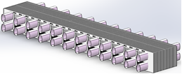
In the early 1970s, a new type of radiator emerged: the assembled radiator. Compared with the traditional brazed radiator, the new product was lighter in weight and more shock-resistant, withstood temperature variation better, as well as pressure pulse and corrosion. Moreover, it boasted a lower cost in mass production and caused no pollution during the fabrication process. Thus, the assembled radiator was widely used in sedans and light buses in Europe. However, early assembled radiators had a lower heat transfer performance than that of brazed radiators because they were made of aluminum and equipped with circular/oval tubes. This shortcoming limited the application of assembled radiators in high-power vehicles. To solve the problem, the flat tube type aluminum assembled radiator was invented in the early 1990s with a heat transfer performance close to the level of the brazed radiator. Figure 1 is an illustration of the flat tube type assembled radiator core body.
Figure 1. Sketch map of flat tube type assembled radiator core body
At present, most assembled radiators are equipped with a flat radiating tube. Compared with the traditional circular tube, the flat tube has a larger heat transfer surface area, and better heat transfer efficiency. Besides, the flat tube needed to transfer the same amount of heat is much lighter in weight and smaller in size than the circular tube.
Although numerous studies have been conducted on the characteristics of flow and heat transfer in round, elliptical, and flat tubes, studies on new types of tubes are limited, especially on special section tubes, recommended that further detailed studies via numerical simulations and/or experimental investigations should be carried out.
As an indispensable part of the radiator, the radiating tube has a certain influence on the distribution of the flow field and the heat transfer efficiency. Through a numerical study of circular and oval tubes of approximately equal diameter and fin area, Li Zhang et al. [6] discovered that the oval tube has a better heat dissipation effect due to its larger surface area. Xiuqin Ma et al. [7] conducted a simulation analysis of how different types of radiating tube affect heat dissipation performance, but the simulation failed to pass experimental verification. Foreign scholars have also conducted a lot of research on the radiating pipe distribution, airside coupled heat transfer, and the establishment of a mathematical model of louvered fin radiator [8, 9, 10]. Xiaoli Yu et al. of Zhejiang University applied CFD simulation technology to the flow field, pressure loss, and heat dissipation characteristics in radiator components, and verified the simulation in a wind tunnel [11]. In this paper, the author compares the heat dissipation performance of flat tube type and wasp-waisted tube type assembled radiators, which have the same structure parameters (base tube equivalent diameter, fin thickness, and fin surface area), under the same conditions.
3.1 Theoretical basis
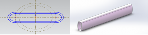
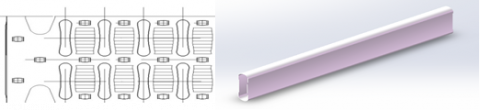
Flat radiating tubes are usually made by pressing a circular tube with the same circumference. See Figure 2. The wasp-waisted radiating tube, however, symbolizes a breakthrough in structural design: maximizing outer circumference and reducing the equivalent diameter without sacrificing the flow area. Besides, the “wasp-waist” increases the area of the radiating fin. Compared with the previous assembled products, the wasp-waisted tube features a much smaller tube spacing, more radiating units, and more compact core structure. See Figure 3.
Figure 2. Sketch map of flat radiating tube
Figure 3. Sketch map of wasp-waisted radiating tube
The radiator has a complex flow and heat transfer process. The fluid flow and heat transfer meet the laws of conservation of mass, energy, and momentum [12, 13].
Conservation of mass equation: The mass increase in fluid microelement per unit time is equal to the net mass which flows into the microelement in the same time interval.
$\frac{\partial \rho}{\partial t}+\frac{\partial(\rho u)}{\partial x}+\frac{\partial(\rho v)}{\partial y}+\frac{\partial(\rho w)}{\partial z}=0$(1)
Conservation of momentum equation: the change rate of the fluid in the microelement with respect to time equals the sum of various external forces acting on the microelement.
$\frac{\partial(\rho u)}{\partial t}+d i v(p u u)=\operatorname{div}(\mu g r a d u)-\frac{\partial \rho}{\partial x}+S_{U}$(2)
$\frac{\partial(\rho v)}{\partial t}+\operatorname{div}(p v u)=\operatorname{div}(\mu g r a d v)-\frac{\partial \rho}{\partial x}+S_{v}$(3)
$\frac{\partial(\rho w)}{\partial t}+\operatorname{div}(p w u)=\operatorname{div}(\mu g r a d w)-\frac{\partial \rho}{\partial x}+S w$(4)
Conservation of energy equation: The increase rate of the energy in the microelement is equal to the net heat flow into the microelement plus the work done by the body and surface forces on the microelement. The conservation of energy equation with temperature T as the variable is:
$\frac{\partial(\rho T)}{\partial t}+\operatorname{div}(p u T)=\operatorname{div}\left(\frac{k}{c_{p}} g r a d T\right)-\frac{\partial \rho}{\partial x}+S_{T}$(5)
Since a radiator involves a large number of heat transfer tubes and a complex fin structure, the computing power of existing computers is not enough to simulate the fluid flow in the radiator. Thus, the radiator model must be simplified to a certain extent.
3.2 Simplification and establishment of geometric model
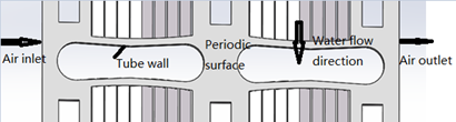
Previous research shows that the thermal resistance of the radiator is mainly concentrated on the airside, which takes up 80% of the thermal resistance of the radiator core. Therefore, the author establishes the airside 3D numerical model for the flat tube type radiator and wasp-waisted tube type radiator of a car model. Because the radiating fin is very thin and large in size, dividing the solid model of the radiator into grids would generate numerous grids and cost a lot of computing resources and time. To reduce the computational load, the fin structure at the core is simplified to an area of porous medium during the simulation of airside heat transfer of the radiator. [14, 15] Moreover, since the fins are periodically arranged, it is only necessary to conduct a numerical simulation of a single heat convection unit, and to properly simplify the calculation model in light of a symmetric boundary and periodic boundary. The author establishes an analytical model by taking one radiating tube and ten half-symmetrical radiating fans (1mm interval) of each radiator, as illustrated in Figure 4.
Figure 4. Geometric model of wasp-waisted tube type radiator
3.3 Basic assumptions and boundary condition settings
With water as the cooling liquid and without considering the structure of the radiating fin, the heat pipe and radiating fin are modeled as one body to eliminate thermal resistance. In addition, the author assumes that the air is incompressible, the physical parameters of the air are constant, the air flow is steady, the velocity direction of the air is vertical to the windward side, and the air is evenly distributed in the windward side, and ignores the impact of air gravity. To ensure the stability of the flow and the reliability of the physical model, the calculation area is extended in all directions rather than just the actual area.
The specific boundary conditions are defined as follows:
1) The air inlet is set as the boundary of velocity inlet y, and the air inlet temperature is set to 293 K.
2) The air outlet is set as the boundary of the pressure outlet.
3) Inlet water temperature: 358 K, water flow: 100 L / min.
4) Wind speed: 2 m/s, 4 m/s, 6 m/s, 8 m/s, and 10 m/s.
5) The fluid is evenly distributed in the flow channel and is fully developed.
6) The upper and lower planes are set as the periodic boundaries.
7) The symmetry plane is set as the symmetrical boundary.
8) The interface between the solid and the fluid regions is the coupled heat transfer surface.
3.4 Results and analysis
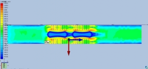
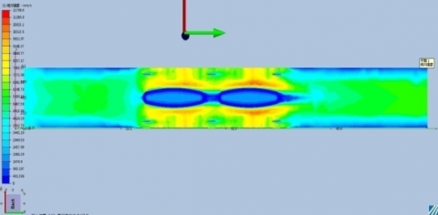
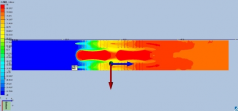
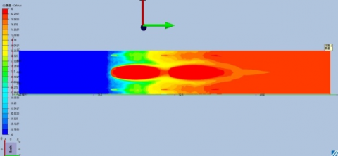
The simulation results of the wasp-waisted tube and the flat tube are described at the air inlet temperature of 293 K, wind speed of 4 m/s, inlet water temperature of 358 K, and water flow rate of 100 L/min. As shown in Figure 5, the air flow rate near the inlet in both figures is increased as the heat pipe reduces the air flow area. For both tubes, the regions with the highest velocity appear in the region near the air inlet and outlet where the air flow channel is much narrower than other places. As the outside wall of the flat tube is a plane surface, the air flows at a uniform velocity, but local turbulence occurs after the air flows around the radiating tube. In contrast, the wasp-waisted tube is a special tube with concave walls and a longer outer circumference than the flat tube. The special shape increases the area of turbulence. The air flow throughout the air channel of the wasp-waisted tube is much more chaotic than that of the flat tube. As shown in Figure 6, the cooling air enters from the left side of the model and keeps transferring heat by convection with the surface of the louver fins, leading to a decrease in the temperature of the fin surface and a gradual increase in the cooling air temperature. As the heat transfer progresses, the temperature difference between the fin surface and the cooling gas becomes smaller and smaller. From the length of the red region, it can be inferred that the heat dissipation efficiency of the wasp-waisted tube is higher than that of the flat tube. What’s more, obvious eddy currents are formed between the two tubes in each figure. There are more eddy currents near the wasp-waisted tube than the flat tube. Under the same conditions, more eddy currents can carry away more heat. For the flat tube, the outlet wind temperature is 350.73 K, and the wind side pressure drop is 161 Pa; for the wasp-waisted tube, the outlet wind temperature is 351.265 K, and the wind side pressure drop is 155 Pa. Thus, the wasp-waisted tube has a higher outlet wind temperature and lower wind resistance than the flat tube, indicating that wasp-waisted tube type radiators dissipate more heat at the wind side than flat tube type radiators. However, the wasp-waisted tube has a higher water resistance because of its irregular shape.
(a) Wind side velocity distribution of wasp-waisted tube
(b) Wind side velocity distribution of flat tube
Figure 5. Wind side velocity distribution
(a) Wind side temperature distribution of wasp-waisted tube
(b) Wind side temperature distribution of flat tube
Figure 6. Wind side temperature distribution
3.5 Comprehensive performance evaluation
As stated above, the flat tube has a lower heat transfer coefficient and a lower water resistance than the wasp-waisted tube. Thus, an increase of the heat transfer coefficient inevitably drives up the pressure drop, which calls for a standard to comprehensively evaluate the performance of radiating tubes. Therefore, the comprehensive evaluation factor of radiating tube performance as the evaluation standard is introduced. Reflecting the energy transferred with the same amount of pump power, the factor gives comprehensive consideration to the influence of heat transfer and pressure drop. The greater the factor is, the better the comprehensive performance. Whereas the comprehensive performance evaluation factor of the wasp-waisted tube is always higher than that of the flat tube, it is proved that a wasp-waist structure can improve the comprehensive performance of radiating pipes.
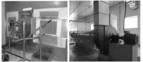
As an internationally used radiator test method, wind tunnel test can accurately measure such performance parameters of radiator as inlet/outlet temperature difference, inlet/outlet pressure drop and heat dissipating capacity by adjusting the cooling air flow rate, water flow, etc. The experiment uses artificial air flow channel to provide cooling air to the radiators. Major experiment equipment include air duct, air duct circulating water circuit, circulating water heating device, wind speed measuring instrument, temperature sensor, pressure sensor, mass flow meter and fan. The air duct creates the flow channel, and the fan provides power. Under the combined action of the air duct and the fan, the air flows through the radiator[16]. In order to compare the performance difference between the two types of radiators, the author conducts a wind tunnel test for each, and draws charts to compare their heat dissipating capacity, wind resistance and water resistance. Figure 7 illustrates the test site.
Figure 7. Wind tunnel test rig
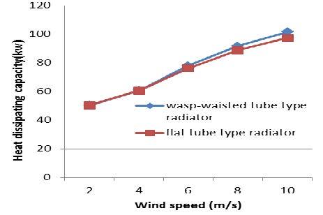
The experiment is carried out at room temperature. The ambient temperature is adjusted to 293 K, and the inlet air temperature fluctuation does not exceed ±5 °C. Besides, no obstacle exists within the distance of three times the air duct diameter from the inlet of the air duct. Five wind speed operating points are selected, namely 2 m/s, 4 m/s, 6 m/s, 8m/s, and 10 m/s. Figure 8 demonstrates the heat dissipating capacity of the two types of radiators under different wind speeds. As shown in the figure, the two types of radiators have a similar heat radiating capacity under low wind speed. As the wind speed increases, the heat radiating capacity of the wasp-waisted tube increases as well because the tube generates more eddy currents than the flat tube. The trend echoes the results of numerical simulation.
Figure 8. Heat dissipating capacity of wasp-waisted tube type radiator and flat tube type radiator
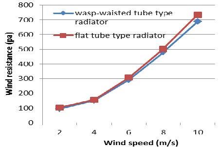
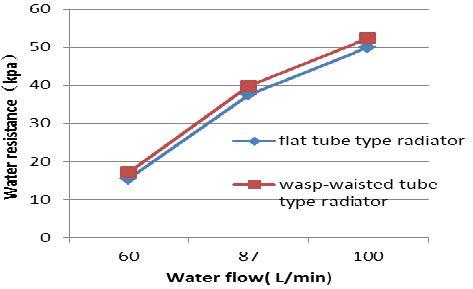
As shown in Figure 9, the wind resistance of both types of radiators increases along with the wind speed. The wasp-waisted radiating tube has a lower wind resistance thanks to the larger fin area because the design maximizes outer circumference and reduces the equivalent diameter. Three water flow operating points are selected, namely 60 L/min, 87L/min, and 100 L/min. As shown in Figure 10, the wasp-waisted tube has a larger water resistance. With the aid of the comprehensive performance evaluation factor, it is found that the wasp-waisted tube type radiator has a better heat dissipation performance than that of the flat tube type radiator. The finding agrees with the results of numerical simulation.
Figure 9. Wind resistance of wasp-waisted tube type radiator and flat tube type radiator
Figure 10. Water resistance of wasp-waisted tube type radiator and flat tube type radiator
From the above simulation analysis and test results, the author concludes that the wasp-waisted tube type radiator has a better comprehensive heat dissipation performance than that of the flat tube type radiator. This finding points out a new direction for research on improving the heat dissipation performance of assembled radiators, that is, to optimize the radiating tube by reducing the equivalent diameter of the tube and expanding the area of the radiating fin, and to seek the optimal balance between thermal efficiency and resistance drop. This is a possible way to resolve the problem that the assembled radiator has always had a lower heat dissipation performance than that of the brazed radiator on cars. Nevertheless, the application range of the wasp-waisted radiating tube is affected by the fact that it differs greatly from traditional radiators in structural strength and bearing capacity because of its unique self-supporting structure formed during the fabrication process, i.e. bending a circular tube in the middle point. Therefore, little academic research has been conducted on wasp-waisted tube type radiators. In the future, it is necessary to further explore the structural strength and pressure capacity of wasp-waisted tube type radiators.
This study was supported by Project of Guizhou Province Science and Technology Program (20146004).
t time
U the weight of the velocity vectors in the x direction
V the weight of the velocity vectors in the y direction
W the weight of the velocity vectors in the z direction
P the pressure on the fluid
Div the divergence of mathematical operator
Grad the gradient of mathematical operator
Su the generalized source terms of the conservation of momentum equation
Sv the generalized source terms of the conservation of momentum equation
Sw the generalized source terms of the conservation of momentum equation
C P specific heat, J. kg-1. K-1
T temperature
k thermal conductivity, W. m-1. K-1
ST the internal heat source
Greek symbols
ρ Density, kg. m-3
μ Dynamic viscosity, kg. m-1. S-1
[1] S. H. Lee, N. Hur, S. Kang, “An efficient method to predict the heat transfer performance of a louver fin radiator in an automotive power system,” J Mech Sci Technol, vol. 28, no. 1, pp. 145–155, Jan., 2014. DOI: 10.1007/s12206-013-0951-8.
[2] D. Antonijevic, “An engineering procedure for air side performance evaluation of flat tube heat exchangers with louvered fins,” Heat Mass Transfer, vol. 49, no. 1, pp. 117-127, Jan., 2013. DOI: 10.1007/s00231-012-1073-z.
[3] Q. J. Guo, X. N. Qi, Z. Wei, et al, “3D numerical simulation and analysis of refrigeration performance of the small diameter vortex tube,” Int J Heat & Tech, vol. 34, no. 3, pp. 513–520, Sep., 2016. DOI: 10.18280/ijht.340324.
[4] S. E. Rafiee, M. M. Sadeghiazad, “Heat and mass transfer between cold and hot vortex cores inside ranque-hilsch vortex tube-optimization of hot tube length,” Int J Heat & Tech, vol. 34, no. 1, pp. 31-38, 2016. DOI: 10.18280/ijht.340105.
[5] S. A. E. Sayed Ahmed, O. M. Mesalhy, M. A. Abdelatief, “Flow and heat transfer enhancement in tube heat exchangers,” Heat Mass Transfer, vol. 51, no. 1, pp. 1607-1630, Nov., 2015. DOI: 10.1007/s00231-015-1669-1.
[6] L. Zhang, K.Yang, W. Liu, “Numerical study on flow and heat transfer in an elliptical and circular finned tube,” Journal of Engineering Thermophysics, vol. 30, no. 9, pp. 1571-1574, Sep., 2009.
[7] X. Q. Ma, J. Zhao, M. Q. Zheng, et al, “Study on the effect of tube type on the heat transfer performance,” Machinery Design & Manufacture, no. 8, pp. 210-213, Aug., 2015.
[8] T. K. Kim, H. C. Kang, J. S. Lee, “A porosity model for flow resistance calculation of heat exchanger with louvered fins,” J Mech Sci Technol, vol. 30, no. 4, pp. 1943-1948, Apr., 2016. DOI: 10.1007/s12206-016-0353-9.
[9] C. Cuevas, D. Makaire, L. Dardenne, P. Ngendakumana, “Thermo-hydraulic characterization of a louvered fin and flat tube heat exchanger,” Exp Thermal Fluid Sci, vol. 35, pp.154-164, Jan., 2011. DOI: 10.1016/j.expthermflusci.2010.08.015.
[10] D. Taler, “Experimental determination of correlations for average heat transfer coefficients in heat exchangers on both fluid sides,” Heat Mass Transfer, vol. 49, no. 8, pp. 1125-1139, Aug., 2013. DOI: 10.1007/s00231-013-1148-5.
[11] Y. Q. Huang, X. L.Yu, G. D. Lu, “Numerical simulation of slit fin cell’s flow and heat transfer,” Journal of Zhejiang University, vol. 42, no. 8, pp. 1462-1468, Aug., 2008.
[12] Z. G. Tong, Y. F. Wang, D. Chen, “Research on the structure optimization of automobile radiators,” Energy Research and Information, vol. 30, no. 2, pp.108-112, 2014. DOI: 10.13259/j.cnki.eri.2014.02.011.
[13] X. F. Pan, W. W. Cao, Q. L. Liu, et al, “Simulation research on car radiator fin,” Journal of Shanghai University of Engineering Science, vol. 28, no. 3, pp. 193-197, Sep., 2014.
[14] Q. L. Meng, M. D. Yin, Z. X. Zhu, “Numerical simulation study of the cold and hot side coupled heat dissipating of the vehicle radiator,” Machinery Design & Manufacture, no. 7, pp. 95-98, Jul., 2015.
[15] S. A. E. Sayed Ahmed, O. M. Mesalhy, M. A. Abdelatief, “Flow and heat transfer enhancement in tube heat exchangers,” Heat Mass Transfe, vol. 51, no. 11, pp. 1607-1630, Nov, 2015. DOI: 10.1007/s00231-015-1669-1.
[16] Y. Wu, J. Z. Guo, L. Hu, et al, “Simulation and test research for the multi-structure of automotive louvered fins heat exchangers,” Science Technology and Engineering, vol. 16, no. 11, pp. 59-64, Apr., 2016.