OPEN ACCESS
This paper solves the floccule floccule-proofing problem encountered in the actual operation of an air air-cooled condenser by relying on the technological alteration project of a 2×660MW pow er plant. Numerical simulation, analysis and research are conducted on the thermos thermos-flow performance of the direct air air-cooled condenser (DACC) in different wind directions under performance assessment conditions. The material, structural style, porosity, resistance co-efficient and installation position of the floccule-proof screen are determined. Floccule-proofing is realized by utilizing an engineering design margin while the air-cooled condenser is made to meet the requirements of performance assessment conditions. The research provides a theoretical basis for the operation and optimal design of a DACC.
Direct air cooled condenser , Floccule Floccule-proof screen, Numeral simulation, Porosity, Optimal design.
Willow and poplar are common tree species in China. Every spring the willow and poplar catkins fly in the air like “spring snow”, scattered everywhere by the wind. When the willow and poplar catkins flutter in the vicinity of a direct air-cooling power plant (DACC), they often build up on the radiator, forming a thick layer of “felt”, which seriously affects the heat transfer performance of the radiator. Therefore, the floccule-proofing problem of radiators has a general character in Chinese air cooling power plants. Until now there has not been any reliable and reasonable floccule-proofing solution for air-cooling power plants at home or abroad.
This paper solves the floccule-proofing problem of the DACC by relying on the technological alteration project of power plants which are already built. For the purposes of floccule-proofing, the engineering design margin is used to ensure the DACC meets the requirements for performance assessment. Numerical simulation research was carried out on the variation in heat transfer of the DACC with and without a floccule-proof screen in different wind directions, taking into account the performance assessment conditions of the DACC, and finally the material, structural style, porosity, resistance coefficient and installation position of the floccule-proof screen were determined. This research provides a theoretical basis for the operation and optimal design of a DACC.
Dingzhou Power Plant is located in the southwest of Dingzhou in the municipal district of Baoding, Hebei Province. The phase II project consists of 2×660MW supercritical units and adopts a mechanical draft direct air-cooled condenser (DACC) system. The cooling elements adopt single-row tubes, the total finned tube area for a single unit is 1, 708, 184m2, of which the parallel flow area is 1, 518, 386m2 and the counter-flow area is 189, 798m2; the ratio of parallel flow area to the counter-flow area is 8:1; the design face velocity face is 2.26 m/s (corresponding to TRL operating conditions). DACCs are arranged outside row “A” of the turbine house; each unit is provided with 56 cooling units, 8 columns of DACCs are arranged in the direction of row A, of which each column contains 7 cooling units, of which 5 cooling units are parallel-flow units and 2 are counter-flow units. The parallel-flow and counter-flow units are respectively provided with parallel-flow and counter-flow axial fans, of which the diameter is 9.754m. The area of DACC platform for each unit is 90×87.78m, and a walkway of 0.5m width is provided between the DACC platforms of the two units [1].
2.1 Performance assessment conditions of DACC
The performance assessment conditions of the DACC are divided into assessment conditions of air cooling island and DACC, and the performance assessment points are respectively located at the outlet of a low pressure cylinder of the turbine and inlet of the DACC. According to the technical agreement for finned tube bundles [2], the main performance assessment conditions of the DACC include TRL operating conditions, TMCR operating conditions, THA operating conditions, chocking backpressure operating conditions, etc. Among them, THA operating conditions for the performance guarantee of finned tube bundles are required to be as follows: the air dry temperature is 17.0℃, the atmospheric pressure is 1010.3hkPa, the volume flow rate of a single axial fan is 450m3/s, the mass flow rate of exhaust wet steam is 1254.78t/h, the enthalpy of exhaust steam is 2454.67kJ/kg and the enthalpy of condensate is 231.60kJ/kg, the temperature difference ITD (initial temperature difference) between the exhaust temperature and the ambient temperature at the inlet of the DACC is 34.04℃, and the back pressure at the inlet of DACC is 13kPa. In the performance assessment conditions, 3.5 m/s wind velocity refers to the external horizontal wind velocity at a point 1.5m higher than the top of the steam distribution duct.
2.2 Numerical simulation test conditions
As the floccule-proof screen is used mainly in April and May, it will be removed before summer in order to reduce resistance of the air supply system. Likewise, the floccule-proof screen is not required for winter operation. Therefore the performance assessment conditions of the turbine involved in the use of the floccule-proof screen are TMCR and THA conditions. Under THA/TMCR conditions, the meteorological condition of the environment and design frontal wind velocity are completely the same. Compared to THA conditions, under TMCR conditions, the thermal load and backpressure are slightly higher. Since the performance assessment of the entire air cooling island does not include TMCR conditions, this paper carries out numerical simulation research on the performance of the DACC under THA conditions of the turbine.
2.3 Resistance and heat exchange performance of the DACC
The performance test for DACC with single-row tubes under the performance assessment conditions was commissioned by Xi’an Thermal Power Research Institute (TPRI). For the resistance and heat transfer characteristics of the DACC, we can refer to the experiment report [3].
The research focus is to determine the influence of a floccule-proofing scheme on the operation of the power plant under performance assessment conditions. The mathematical model of the research problem is built through reasonable simplification according to the physical model.
3.1 Mathematical model
Under the influence of steady-state incompressible ideal gas, the buoyancy effect and the flow and heat transfer of air should satisfy equations of mass conservation, momentum conservation and energy conservation. For the purpose of analysis of each control equation and the solution to each control process using a unified program, it is required to develop a general form of basic control equations. The continuity equation, momentum equation and energy equation that describe the flow and heat exchange of the air cooling island as well as thermal conduction differential equation that describes thermal conduction of solid wall surface can be written into the following general form uniformly [4]:
$\operatorname{div}(\rho \vec{U} \phi)=\operatorname{div}\left(\Gamma_{\phi} \operatorname{grad} \phi\right)+S_{\phi} $ (1)
where, $\rho$ is air density, kg/m3; $\vec{U}$ is the air velocity vector, m/s;$\phi$ is a general variable, which can be solved by representing $u$ , $\mathcal{V}$ , $\mathcal{W}$ , $T$, etc.; $\Gamma_{\phi}$ is the generalized diffusion coefficient; and $S_{\phi}$ is the term of generalized source.
Table 1 gives the corresponding relationships between the three symbols and specific equations, where $\mu$ is the dynamic viscosity coefficient of air, $\lambda$ is the thermal conduction coefficient of air, $c_{p}$ is specific heat capacity, and $S_{T}$ is the term of viscous dissipation.
Table 1. Specific forms of symbols in the general control equation
|
Symbol |
$\Phi$ |
$\Gamma$ |
$S$ |
|
Continuity equation |
1 |
0 |
0 |
|
Momentum equation |
$\mu_{i}$ |
$\mu$ |
$-\frac{\partial p}{\partial x_{i}}+S_{i}$ |
|
Energy equation |
$T$ |
$\lambda / c_{p}$ |
$S_{T}$ |
3.2 Geometric model
The numerical computation model includes a geometric model, a grid scheme and boundary conditions. The detailed geometric model of the DACC island is built according to the as-built drawing. The range of the entire computational area is 2000×2000×800m. As shown in Figure1, within the computational area there are such high-rise buildings and structures as a turbine house, a coal bunker bay, boiler house, electro-precipitator (ESP), stack, elevator, etc.
For the definition of the azimuth angle of wind direction in the numerical simulation, refer to Figure1. From right to left are 1#, 2#, 3# and 4# units. Phase Ⅰ project is 1# and 2# units, Phase II project is 3# and 4# units. The incoming wind from the main air intake side of the DACC platform is 0° wind direction and rotates clockwise, and the incoming wind from the back of boiler house is 180° wind direction. Parallel to the direction of 1#~4# units, the incoming wind from direction of phase II project is 90° wind direction, and the incoming wind from direction of phase I project is 270° wind direction.
The detailed geometric model of the air cooling island includes concrete support columns, a maintenance walkway, windbreak wall, steam distribution pipe, unit partition wall, floccule-proof screen, fan air funnel, etc. The height of the concrete support column is 38.5m and its diameter is 4.0m. The elevation of the DACC platform is 45m and the height of windbreak wall is 13.8m. The dimensions of the elevator are 3.0×3.0×58.8m. The widths of the corridor on the ACC platform are 1.8m, 1.0m and 0.5m, respectively.
Figure 1. Definition of azimuth angle of wind direction
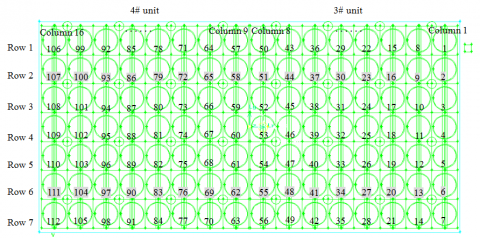
The numbers of parallel-flow and counter-flow air cooling units and fans are shown in Fig.2;the numbers with a white background are parallel-flow fan units, and numbers with a gray background are counter-flow fan units. Each air cooling unit and fan unit has two radiators. The fan unit only has one unit partition wall and there is no partition wall between the two columns of the air cooling units. Along a direction perpendicular to the steam distribution pipe, from right to left starting from elevator side of 3# unit, are columns 1 to 16 respectively. Along a direction parallel to the steam distribution pipe are rows 1 to 7 respectively.
Figure 2. Definition of parallel-flow and counter-flow air cooling units and fan units
The plane dimensions of the air cooling unit are 11.25×12.54m, the elevation of the fan is 44.23m, the fan diameter is 9.754m, the height of the air duct is 2.1m and the inlet diameter of fan air funnel is 10.354m. The angle between the tube bundles of the DACC is usually 60°, and the actual angle between the tube bundles for this project is 59.4°. In modeling, the actual angle between the tube bundles of the DACC is 61.76°. Assume the diameter of each steam distribution pipe is 2.0m, and neglect the upper and lower headers of the tube bundle.
Each air cooling fan unit has two radiators. The numbering rule of radiators is: designate and number from right to left according to the sequence of air cooling units and fan units. A single unit has 112 radiators and two units have in total 224 radiators.
3.3 Grid scheme
In order to satisfy the requirements for computation accuracy and time, we have adopted the method of segmental grid division to divide the grids of the computational area. Non-structured grids are used for the interior of the air cooling island and structured grids are used for other computational areas. The entire computational area is from (-1000, -1000, 0) to (1000, 1000, 800) m, and the center of the DACC is located at the origin of the computational area. After the irrelevance inspection of grid numbers [5], the total grid cells are 14, 655, 247 and the nodes are 9, 288, 742.
3.4 Boundary conditions
Boundary conditions are describes as follows:
3.4.1. Velocity inlet
The velocity inlet boundary condition is adopted for the inlet of the entire flow computational area [6]. The wind velocity is distributed along the height and the function of atmospheric boundary layer of equation (2) is adopted.
$\frac{v_{i}}{v_{0}}=\left(\frac{h_{i}}{h_{o}}\right)^{\alpha}$ (2)
where $h_{0}$ is the height of anemometer; $v_{0}$ is average wind speed at the location of $h_{0}$ ; $h_{i}$ is arbitrary height; $v_{i}$ is average wind speed at $h_{i}$, $\alpha$ is roughness index of ground. The ground roughness can be divided into 4 kinds, A, B, C and D. Type A refers to offshore sea surface, sea island, coast, lakeshore and desert areas, $\alpha=0.12$; type B refers to field, countryside, forest, hill as well as towns and suburb with sparse houses, $\alpha=0.16$ ; type C refers to an urban area with dense groups of buildings, $\alpha=0.22$; and type D refers to an urban area with dense groups of buildings and taller houses, $\alpha=0.30$. In the simulation, the roughness co-efficient of the ground is$\alpha=0.16$ .
Generally, the height of the anemometer in the meteorological station is 10m. The user defined function of the inlet boundary is written. Usually, the wind velocity [7, 8] is the mean velocity over time of the undisturbed ambient air flow approximately 1m above the upper edge of the steam distribution pipe. When the ambient wind velocity measured at the meteorological station is 2.63m/s, the ambient wind velocity at performance assessment conditions is 3.5m/s.
3.4.2 Ambient boundary
The top surface of the flow field does not have an actual boundary and is treated as a free slip boundary. The peripheral boundary is relatively remote from the air cooling island, the flow field at this location is basically not influenced by the air cooling island, and is thus taken as the ambient parameter. The ground surface is a no-slip condition of solid wall.
3.4.3 Air cooling axial fan
The fan group mainly includes an axial fan, gearbox and motor. The fan group is divided into a parallel-flow fan group and a counter-flow fan group. When the parallel-flow and counter-flow units have the same tube bundles and dimensions, for the purpose of maintenance and service, the same size and different angle of the blade can be selected for parallel-flow and counter-flow fans [9].
An air cooling low-noise axial fan of 9.754m diameter for a power station is selected. Both parallel-flow and counter-flow axial fans have 8 blades and their hub diameter is 1.45m.
The accurate position of each fan is determined in the model, taking into consideration the effect of the swirling flow. The radial speed and tangential speed are set to the given fans [10].
a) Fan performance under TRL performance assessment conditions
The meteorological parameters under TRL performance assessment conditions of the turbine are the design conditions of the air cooling fan. The blade angle of the parallel-flow fan is 18.5°, and at 100% nominal rotating speed (about 61.7rpm), the air volume of the fan is 540m3/s and the static pressure is 96.9 Pa. Fit the fan performance curve according to the test data. The relationship between the static pressure of the parallel-flow fan and the wind velocity is shown in the following expression:
$P=190-0.1133 v-1.7849 v^{2}$ (3)
The blade angle of counter-flow fan is 17.5°, and at 100% nominal rotating speed (about 61.7rpm), the air volume of the fan is 524 m3/s and its static pressure is 95.9 Pa. Fit the fan performance curve according to the test data. The relationship between the static pressure of the counter-flow fan and the wind velocity is shown in the following expression:
$P=190-0.48 v-1.8666 v^{2}$ (4)
b) Fan Performance under THA performance assessment conditions
The performance parameters of the fan are generally based on the meteorological condition of the plant site, delivery conditions or standard design conditions. During the design and selection of fan, attention should be paid to the changes in operating conditions. In the variable-condition computation of the DACC, the fan performance, particularly shaft power, should be corrected due to any change in the atmospheric pressure, ambient temperature and rotating speed of the fan [11].
At nominal rotating speed under THA conditions, the performance curve of parallel-flow and counter-flow fans is as shown in equations (5) and (6).
$P=210-2.0376 v-1.7813 v^{2}$ (5)
$P=210-2.4627 v-1.8631 v^{2}$ (6)
Under THA performance assessment conditions, the operating air volume of the parallel-flow fan is 450m3/s, which is about 83.33% of the design volumetric air flow. The range of volumetric air flow during stable operation of the fan is 300~617m3/s, and range of wind velocity is 4.0~8.25m/s. At 83.33% nominal rotating speed (about 51.4 rpm), the volumetric air flow at the design point of the parallel-flow fan is 450m3/s, and the wind velocity is 6.022m/s. At 83.33% nominal rotating speed under THA conditions, the performance curve of parallel-flow fan is as shown in Equation (7).
$P=145-1.421 v-1.8032 v^{2}$ (7)
The volumetric air flow of counter-flow fan is 436.667m3/s, which is about 83.33% of design air volume of 524m3/s. At 83.33% nominal rotating speed (about 51.4 rpm), the volumetric air flow at design point of the counter-flow fan is 436.667m3/s, and the wind velocity is 5.84m/s. At 83.33% nominal rotating speed under THA conditions, the performance curve of the counter-flow fan is as shown in Equation (8).
$P=145-1.7705 v-1.886 v^{2}$ (8)
3.4.4 Air cooled heat exchange unit
The basic heat exchange elements of the DACC are single-row tubes. Tube bundles composed of multiple heat exchange elements constitute “A” frame and constitute one heat exchange unit with a large-diameter axial fan provided underneath. Multiple heat exchange units constitute the DACC. Therefore, the geometric structure of the DACC is very complex. If the model is built according to actual situation, this will certainly result in a huge amount of computation work, insufficient computer resources, and it is difficult to obtain reasonable and accurate computation results. Therefore, it is needed to reasonably simplify the air cooling unit.
In FLUENT, the heat transfer and resistance models that can be used for simulating the characteristics of the air cooled unit and the DACC include an internal energy source model, heat exchanger model and radiator model [12]. In the computation of the internal energy source model, temperature singularity tends to occur. The heat exchanger model is divided into two types: a simple heat exchanger efficiency model and a model for a number of heat transfer units (NTU) [13]. In the input of heat exchanger model, test data on some parameters is lacking; at the same time, some limiting conditions need to be considered when a FLUENT heat exchanger model is used [14]. A radiator model can be set flexibly according to the actual resistance and heat transfer characteristics of the DACC; therefore, this paper adopts the radiator model.
The resistance characteristics of the DACC include a porous media zone, resistance coefficient method, porous jump, etc. The porous media zone and porous jump method can better simulate the characteristics of the DACC at different frontal wind velocities of the tube bundles. In the research, the method of resistance coefficient is adopted to simulate the resistance characteristics of the DACC radiator at different frontal wind velocities of the tube bundles and a porous jump is adopted to simulate the resistance characteristics of a floccule-proof screen.
Both the parallel-flow unit and counter-flow units adopt the same heat transfer and resistance characteristics. The surrounding windbreak wall and unit partition wall adopt the solid wall boundary condition.
3.4.5 Porous jump model for fan protection screen and floccule-proof screen [15, 16]
The fan protection screen is rectangular and its dimensions are 10.5×10.6m. A hot dip galvanized steel grille is used and its grids are geater than 100×100mm. The weight of the fan protection screen of each cooling unit is about 3 tons and the load of the fan protection screen is not less than 100kg/m2. The perpendicular distance between the fan protection screen and the inlet plane of the air funnel is about 100mm.
The resistance of the fan protection screen is negligible in the simulation because it is very small. The resistance characteristic of the floccule-proof screen is determined by the test. A porous jump boundary condition is used for simulating the thin membrane with a known speed/pressure drop. It is essentially a one-dimensional simplification of a porous media zone model. The application example includes simulation of a pressure drop across filter paper, screen mesh, filter, perforated plate, and an array of pipes, as well as a radiator without heat transfer. Because the porous jump model has very good robustness and convergence, the porous jump model should be adopted as far as possible to substitute for the full porous media model.
The membrane medium has limited thickness. The pressure drop through it is defined as the combination of Darcy law and additional inertia loss, that is, Forchheimer’s equation:
$\Delta p=-\left(\frac{\mu}{\alpha} v+\frac{1}{2} C_{2} \rho v^{2}\right) \Delta m$ (9)
where, $\mu$ is the dynamic coefficient of viscosity of laminar fluid, N∙s/m2; $\alpha$ is the permeability of the medium, m2; $C_{2}$ is pressure-jump coefficient, which can be obtained through test, l/m; $v$ the velocity of fluid perpendicular to the porous surface, m/s; and $\Delta m$ is thickness of the membrane, $m$.
The screen is widely used in industry, for example, for turbulence reduction in a wind tunnel, various kinds of dehydration processes and filtration process, etc. in paper making and drying as well as a window screen for preventing entry of mosquitoes and insects, an insect-proof screen for preventing the entry of insects in agriculture, etc. In buildings, the common screen windows are usually of 14~20 meshes with a 0.16~0.28mm filament, and the mesh hole is of rectangular or square shape. In recent years, people are interested in determination of the resistance coefficient of the screen through test and theory under different flow conditions.
4.1 Form of the floccule-proof screen
The characteristics of the floccule-proof screen mainly include material, structural style, cleaning, installation position, etc.
4.1.1 Material
The characteristics of the floccule-proof screen include material, structural style, number of frictions, mass per unit area, softness, longitudinal and latitudinal deformation, longitudinal and latitudinal deformation pull force, shear adhesiveness, solvent resistance, resistance to microbe attack, low-temperature resistance, outdoor exposure, self-pollution, toxicity, tensile strength, bending endurance, etc. [17].
There are metallic and non-metallic materials for the floccule-proof screen, including plastic filament, chemical fiber filament (e.g., nylon filament), PVC filament, fiberglass plastic-coated filament, stainless steel wire, aluminum-magnesium alloy wire, zinc-plated wire, aluminum wire, etc.
Non-metallic mesh screen, e.g. plastic window screening, is susceptible to thermal expansion and cold contraction with relatively big deformation probability and poor fire resistance.
The metallic mesh screen is characterized by: high strength and high toughness; resistance to mosquitoes, flies and insects; resistance to high temperature and flame retardancy; resistance to low temperature, air permeability and photo-permeability, bright and pretty surface color and luster, and small resistance compared to a common nylon window screen.
Stainless steel screen has the advantages of resistance to acid and alkali, corrosion, no deformation, resistance to tension, resistance to microbe attack, ease of cleaning, etc. Stainless steel grades are divided into 302, 304, 304L, 316, 316L, etc. In order to prevent increased resistance by a floccule-proof screen due to oxidation of the metal surface and to facilitate cleaning, this paper selects stainless steel 304 to fabricate the floccule-proof screen.
4.1.2 Structural style and cleaning
There are various structural types of industrial screen. For a direct air cooling system, the structural style of the floccule-proof screen should be simple in order to reduce resistance by the floccule-proof screen, avoid adhesion of foreign matter, reduce cleaning difficulty and prevent damage to the floccule-proof screen due to cleaning water pressure that is too high. This paper adopts a mono-filament thread woven screen. The static pressure of the axial fan for the DACC is about 100Pa, the resistance by the floccule-proof screen generally accounts for about 10%~20% of total resistance of the air supply system, since too high resistance will affect the operating economy of the DACC system. In actual operation, the static pressure and power of the fan can be increased appropriately in order to avoid frequent flushing of the floccule-proof screen and save water resources. Technical and economic comparison should be made for the balance between increased electric consumption of the fan and water conservation.
In the actual operation, the porosity and resistance of the floccule-proof screen are in the process of dynamic change; its porosity ranges from 0.6 when it is clean, to 0 when it is totally blocked, and resistance is increased from 12Pa to infinity. When the metallic screen is working, the floccule is accumulated on the screen. The floccule prevention and interception effect between different kinds of floccule-proof screens is gradually reduced and finally tends to become the same. In actual operation, we can decide whether the floccule-proof screen should be cleaned or not according to the exhaust pressure of the turbine, outlet pressure of the exhaust steam box or inlet pressure of the ACC measured by the DCS system of the direct air cooling system. Water source for cleaning can adopt softened water of the DACC cleaning system or an atomizing humidifier.
4.1.3 Installation position
The floccule-proof screen can be installed on the inlet plane of the fan air funnel or the plane of the fan protection screen. Installation on the fan protection screen helps to increase the strength of the floccule-proof screen, reduce resistance by the air supply system and protect important equipment below the air cooling island.
When there is too much foreign matter covering the floccule-proof screen, the weight of the screen is increased and it is stretched downward when the fan stops running or decelerates; and cleaning of floccule-proof screen will also cause downward deformation of the screen. When the fan is running, the screen is pulled up under the action of wind pressure due to the increase in resistance. Such long-term repeated action may cause breakage of the floccule-proof screen. When the pressure of the cleaning water for the floccule-proof screen is too high, this may also cause it to break. When the floccule-proof screen is installed on the fan protection screen, the fan protection screen can provide effective support.
Because the resistance of the floccule-proof screen is proportional to the square of its frontal wind velocity, the floccule-proof screen installed on the fan protection screen is helpful to reducing the resistance of the air supply system. Because the frontal area of the floccule-proof screen installed on the fan protection screen is bigger than that of the fan air funnel, under the same volumetric air flow, the frontal wind velocity of the floccule-proof screen can be reduced, thus reducing the resistance of the air supply system of the DACC and the electricity consumption of the fan and improving the operating economy of the power plant.
The floccule-proof screen should be installed before the advent of willow and poplar catkins during the operation of the power plant. After poplar and willow catkins disappear, generally, the floccule-proof screen should be dismantled in order to reduce resistance of the air supply system. There are many important devices under the DACC platform, for example, HV plant transformer, main transformer, starting/standby transformer, 500kV outgoing line and 220kV incoming line, etc. In order to prevent any accident, it is also very convenient to install and dismantle the floccule-proof screen on the fan protection screen.
4.2 Mesh and porosity
Different types of screen have different characteristics. For example: porosity, mesh size, wire thread size (e.g. diameter or thickness), texture (e.g. knitted, woven, or braided). Among them, porosity is the most important characteristic of screen.
The porosity $\varepsilon$ of three-dimensional porous media refers to the ratio of fluid volume to total volume (including fluids and screen) [18]. The porosity of three-dimensional porous media can be determined by measuring the mass of the solid under a vacuum state and atmospheric condition. In addition, when the screen is deformed, the porosity is not a constant.
$\varepsilon=V_{a} / V$ (10)
where $V_{a}$ is the fluid volume, m3; $V$ is the total volume of fluid and screen, m3.
Because the porous material is very thin, so it can be simplified to a two-dimensional problem. For a rectangular screen of monofilament simple structure, the porosity $\varepsilon$ is defined as [19]:
$\varepsilon=\frac{(l-d)(m-d)}{m l}$ (11)
where $l$ and $m$ are respectively the distance between weft threads and between warp threads of adjacent threads, m.
For a two-dimensional square screen, the porosity $\mathcal{E}$ expressed in percentage is defined as follows [20, 21]:
$\varepsilon=\left(1-\frac{n d}{25400}\right)^{2} \times 100$ (12)
where $d$ is the diameter of the thread, μm; $n$ is the mesh number.
In order to keep consistent with past research, the present paper adopts equations (11), (12) to determine the porosity of the filter screen.
4.3 Resistance characteristics of the screen
When steady-state incompressible fluid passes the screen, generally 2 methods [22] are adopted to determine the characteristics of the screen. One is the method of discharge coefficient $C_{d}$ that combinesa Bernoulli equation or method of resistance coefficient $\xi$; the other is the porous media method.
4.4 Determination of the form of the floccule-proof screen
Determine the influence of floccule-proof screen on resistance of air supply system at different porosity and different Reynolds number. Then conduct numerical simulation of the air cooling island with a floccule-proof screen of different stainless steel so as to screen out the porosity of the floccule-proof screen that meets THA performance assessment conditions of the air cooling island. Finally, determine the form of the floccule-proof screen, and control its influence on the performance of the air cooled condenser within the margin range reserved for the air-cooled condenser in the original design.
Finally, select the floccule-proof screen of stainless steel with 14-mesh square holes, 0.4mm wire diameter and approximately 0.6077 porosity. Build a porous jump model of the floccule-proof screen, and determine the change in heat exchange of the DACC system before and after the installation of the floccule-proof screen through numerical study.
The computer hardware adopts a parallel computing graphic workstation HP Z800 with 8 cores, 2.67GHz processor and 32GB memory. The software adopts Exceed 11, Gambit 2.4.6, ANSYS Fluent 6.3.26 for study under the Windows Professional XP 64-bit operating system.
5.1 Absence of the floccule-proof screen
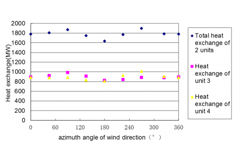
Under THA condition of the steam turbine and when the fan works at 83.33% nominal speed, the heat exchange capacity of the DACC in different wind directions is shown in Figure3. In the design of the DACC, the main windward side of the DACC platform generally faces the prevailing wind direction in summer, i.e. 0° wind direction. It can be seen from the figure that the incoming wind from the back of the boiler at 180° is the adverse operating condition. In the 90° and 270° wind direction, the heat exchange of the DACC is better. In other wind directions, the heat exchange capacity of the air-cooled radiator is slightly reduced. In the absence of the floccule-proof screen, the DACC system can realize full capacity of the unit in summer. Under adverse operating conditions, the heat exchange capacity of the DACC of 3# unit is a little higher than that of 4# unit; the heat exchange capacity of 4# unit is 4.20% higher than rated heat load.
Figure 3. Heat exchange capacity of the DACC in different wind directions in absence of a floccule-proof screen
Compared with the rated heat exchange capacity of 1550.6MW of DACC (the heat exchange capacity for a single DACC is 775.3MW) under THA performance assessment conditions, the average value of the total heat exchange capacity of DACC in each wind direction is 115.08% of the design heat exchange capacity; and the average value of the heat exchange capacity of the DACC for 3# unit and 4# unit in each wind direction is respectively 115.19% and 114.93% of the design heat exchange capacity.
5.2 Presence of the floccule-proof screen
Conduct the simulation of all wind directions under THA conditions when the floccule-proof screen is being placed on the fan protection screen; the computation results are shown in Fig.4. Compared to Fig.3, in the presence of the floccule-proof screen, the heat exchange capacity of the DACC has somewhat decreased. Even in the adverse wind direction, the selected floccule-proof screen can also meet the requirements of full capacity of a power unit in summer. Under adverse operating conditions, the heat exchange capacity of the DACC of 3# unit is a little higher than that of 4# unit; the heat exchange capacity of 4# unit is 1.08% higher than the rated heat exchange capacity.
Figure 4. Heat exchange capacity of the DACC in each wind direction in the presence of a floccule-proof screen
Compared with the rated heat exchange capacity of 1550.6MW of DACC (the heat exchange capacity for a single DACC is 775.3MW) under THA performance assessment conditions, the average value of the total heat exchange capacity of the DACC in each wind direction is 111.25% of the design heat exchange capacity; and the average value of heat exchange capacity of the DACC for 3# unit and 4# unit in each wind direction are respectively 111.32% and 111.14% of the design heat exchange capacity.
Taking 4m/s incoming flow velocity (frontal wind velocity of the floccule-proof screen) as an example, after the floccule-proof screen is installed, the resistance will be increased by about 12Pa. If the design wind pressure of the fan is 100 Pa, that indicates that the resistance of the air supply system is increased by 12%; according to the relationship between the air volume of the fan and wind pressure, the air volume will be reduced by about 10%. According to the computation based on this air volume, the frontal wind velocity of the tube bundle will also be reduced by about 10%, and the heat exchange capacity of the DACC will be reduced by about 3~4%.
Compared to the average value of the heat exchange capacity of the DACC in each wind direction in the absence of a floccule-proof screen, the average total heat exchange capacity of the DACC and the average heat exchange capacity of each unit in the presence of a floccule-proof screen is respectively reduced by 3.83%, 3.87% and 3.79%, which are within the range of 3~4% of the above engineering design. Therefore, the resistance coefficient of the floccule-proof screen does not need to be corrected.
5.3 Comparison and analysis
Conduct numerical simulation of the performance of an air-cooling island in different environmental wind directions and obtain the volumetric flow of each fan of the DACC and heat exchange capacity of an air-cooling unit in the absence and presence of a floccule-proof screen. Analyze the volumetric flow of each fan of the DACC and heat exchange capacity of the air-cooling unit with or without a floccule-proof screen by taking the wind coming from behind the boiler house as an example.
5.3.1 Effect on the operating conditions of the fan
For the operating conditions of each fan with and without a floccule-proof screen when the wind comes from behind the boiler house, see Figure5. For each column of air-cooling units, the first row of fans of the air-cooling unit on the windward side has the minimum air volume; next is the second row of counter-flow fan units. The fans in the first column and 16th column of air-cooling units exposed to outside the steam turbine house have a smaller air volume. In addition, because the first column and 16th column have different position relative to the steam turbine house, the air volume is also different.
After installation of the floccule-proof screen, the air volume of each air-cooling unit is reduced somewhat except for several middle air-cooling units in the first row.
Figure 5. Air volumetric flow of each fan with and without a floccule-proof screen
5.3.2 Effect on the performance of an air-cooled condenser
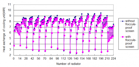
For the heat exchange capacity of each radiator of the unit with and without a floccule-proof screen when the wind comes from behind the boiler, see Fig.6. The unit heat dissipation capacity of each column of units is also minimal because of the air volume of the air cooling unit on the windward side. In the column of heat exchange units exposed to outside the steam turbine house, the heat dissipation capacity of air-cooling units on the right and left sides is smaller; in the same unit, the heat dissipation capacity of the tube bundles at both sides presents a noticeable difference. In the air-cooling units of the middle column, the difference of the heat dissipation capacity between the radiators on the right and left side is smaller.
After installation of the floccule-proof screen, the heat exchange capacity of each air-cooling unit is reduced to some extent, except for several middle air-cooling units in the first row.
Figure 6. Heat exchange capacity of each radiator with and without a floccule-proof screen
The above computations are the simulation results under the condition of a steady incoming flow and steady-state heat transfer. In fact, the atmospheric boundary-layer theory and DACC numerical model still kept improving, and because the outdoor meteorological parameters have the nature of randomness, the airflow parameters for a given direction are hard to sustain and keep stable. Therefore, in actual operation, there exists a certain difference between the performance of the DACC and the results of the above simulation computations.
In this paper we have carried out research and analysis on different types of floccule-proof screens, and determined the material, texture, porosity, resistance coefficient and installation positions of the floccule-proof screen in combination with numerical simulation of the air cooling island. The resistance characteristics of the floccule-proof screen at different porosity and Reynolds number are determined. The floccule-proof screen finally determined is the round stainless steel wire screen with 14-mesh square holes with a 0.4mm wire diameter and 0.6077 porosity.
The numerical simulation of the air cooling island shows that: under THA performance assessment conditions of the steam turbine, the adverse wind direction of the DACC is the wind from behind the boiler house. After the floccule-proof screen is installed on the fan protection screen, the heat exchange capacity of the DACC for 3# and 4# units under THA conditions is respectively 103.68% and 101.08% of the originally designed heat exchange capacity, which meets the original design requirements. That is to say, the floccule-proof purpose is realized by utilizing an engineering design margin while the DACC is made to meet the requirements of performance assessment conditions.
The present research provides a theoretical basis for the operation and optimal design of the DACC.
The financial support for this research, from the National Basic Research Program of China (973 Program) (Grant No. 2009CB219804) and the North Institute of Water Conservancy and Hydroelectric Power Youth Supporting Progr am (Grant No. HSQJ 20 09024 ), is gratefully acknowledged.
1. Northwest Electric Power Design Institute, Design notes to air cooling system at design stage of as-built drawings of phase II air cooling island project of Dingzhou Power Plant of Hebei Guohua Electric Power Co., Ltd. [R]. Xi’an, Shanxi, Feb.2010.
2. Northwest Electric Power Design Institute. Attachment to the contract on finned tube bundles of direct air cooling system for phase II project 2×660MW supercritical thermal units of Dingzhou Power Plant of Hebei Guohua Electric Power Co., Ltd. Dingzhou, Hebei, July.2007.
3. Chen Shengli, Performance test report of Shuangliang Eco-energy Systems Co., Ltd. on direct air cooled condenser unit with single-row tubes for power station, Dec. 2007.
4. Tao Wenquan, Numerical Heat Transfer, Xi’an, Shanxi Province, 2001.
5. P.J. Roache, “Perspective: a method for uniform reporting of grid refinement studies,” Journal of Fluid Engineering, vol. 9, pp. 405-413, 1994.
6. The Ministry of Construction of the People’s Republic of China, GB50009-2001: Code for the design of building structures, Jan. 2002.
7. DL/T244-2012: code for performance test of direct air cooling system [S], 2012.
8. VGB guideline for acceptance test measurement and operation monitoring of air-cooled condenser under vacuum condition (VGB—R131Me).
9. Hebei Guohua Dingzhou Power Generation Co., Ltd. Technical agreement on fans of direct air cooling system for phase II project 2×660MW supercritical thermal units of Dingzhou Power Plant of Hebei Guohua Electric Power Co., Ltd.
10. Shi Lei, Mo Zigao, “Analysis of effect of fan model on numeric research of direct air cooling unit,” Thermal Power Generation, vol.1, pp. 31-34, 2011.
11. Teaching materials for examination and review of heating, ventilation and air conditioning discipline for national certified engineer of public utilities in survey and design. Beijing: China Architecture and Building Press, 2005.
12. Shi Lei, Shi Cheng, Li Yulei, “Building of numeric model of air cooling unit for simulation of direct air cooled condenser,” Thermal Power Generation, vol.6, pp.21-23, 2010.
13. Kröger D.G., “Air-cooled heat exchangers and cooling tower: thermal-flow performance and design,” Vol.1 Penwell corporation, Tulsa, Oklahoma, 2005.
14. FLUENT 6.3 User’s Guide, 2006. Fluent Inc.
15. Shi L., J. Wang, C. Shi and Y.D. Cheng, “Investigation on the Performance Characteristics of Direct Air Cooled Sample Unit,” 2009 Second International Conference on Modelling and Simulation, Manchester (ICMS 2009), Vol.1, Manchester, England, UK, May.21-22, 2009.
16. Shi Lei, Shi Cheng, Huang Xiang, “Research on flow and heat transfer performance of direct air cooled condenser unit prototype,” Thermal Power Engineering, vol.1, pp.73-76, 2009.
17. Li Xionghui, Hu Ping, Yang Yong, “Development and research of PE-coated glassfiber screen window cloth,” Plastic Science and Technology, vol.12, pp. 35-37, 2005.
18. Antonio F. Miguel, “Airflow through porous screens: from theory to practical considerations,” Energy and Buildings, vol.28, pp.63-69, 1998.
19. Meir Teitel, “The effect of screened openings on greenhouse microclimate,” Agricultural and Forest Meteorology, vol.143, pp.159-175, 2007. DOI: 10.1016/j.agrformet.2007.01.005.
20. Wu Dacheng, Synthetic Fiber Melt Spinning, Beijing: China Textile & Apparel Press, 1980.
21. Wang Weixiang, “Research on air blowing device for spinning cooling,” Master dissertation of Donghua University, 2003.
22. P. Munoz and J.I. Montero, “Effect of insect-proof screens and roof openings on greenhouse ventilation,” Journal of Agriculture Engineering Resources, vol.73, pp.171-178, 1999. 270