OPEN ACCESS
Heat storage systems using phase change materials (PCMs in the following) are an effective way of storing thermal energy due to the high energy storage density and the isothermal nature of the storage process. In recent years the utilization of PCMs has been also considered in the thermal control of compact electronic devices. In the present work a parametric analy-sis is presented for an energy storage system with a phase change material, undergoing a heat flow boundary condition, as happens in the electronic equipment cooling. In particular we analyze a hybrid systems composed of a finned surfaces partial-ly filled with PCM. This solution which combine both passive (PCM) and active (fins and fans) cooling solutions, seems to be of interest in high power amplifiers characterized by different levels of power dissipation. This is the case of the telecom base station power amplifiers, where the power is proportional to the traffic load. The results are obtained with a specific fi-nite volumes code. The mathematical model is made dimensionless to allow the characteristic parameters to be evidenced. The proposed parameterization lends generality to the results obtained. In particular the relationships have been investigated between the melting point of the PCM and the operating temperature reached during the peak of the input power. The study provides useful information for the design of these passive cooling systems.
(Presented at the AIGE Conference 2015)
PCM, Electronic cooling, Parametric analysis.
The heat generated by an electronic circuitry must be dissipated to prevent immediate failure and assure long term reliability. For high specific power and/or compactness, the limited capability of the traditional air cooling techniques requires the use of new technologies. In recent years in this area cooling systems based on phase change materials (PCMs in the following) seem to be very attractive techniques of thermal control.
More in general, heat storage systems using PCMs offer effective opportunities for managing thermal energy due to the high energy storage density and the isothermal nature of the storage process. Latent heat storage systems have been widely used in building envelopes, residential heating and cooling, solar engineering, and spacecraft thermal control applications [1].
More specifically, the utilization of PCMs in thermal control of compact electronic devices, try to profit from the advantages offered by these materials, such as: high specific heat, high latent heat, small volume change during phase change, availability of PCMs at convenient melting temperatures, non-toxicity, inertness and non-corrosiveness. A PCM energy storage system can be useful also to delay the heat release so to reduce the need of heat transfer surface, in particular for situations where the heat dissipation is of periodic nature or a sudden transient.
As the base case of thermal control unit (TCU in the following), a layer of PCM encapsulated in a hermetically sealed container can be considered. Referring to this solution, Alawadhi and Amon [2] investigated the thermal energy management issues associated with portable electronic equipment. Tan and Tso [3], experimentally studied the cooling of a mobile electronic device using a PCM based TCU inside the device. Kandasamy et al. [4], investigated experimentally the effect of orientation of PCM based heat sinks.
In applications [2-4] the low thermal conductivity of the PCMs made the charging and discharging slow during phase transitions. Different solutions were then developed to enhance the heat transfer in these PCM based TCUs, all related to the insertion of conducting paths or materials in the heat storage volume: discrete elements such as pins and fins, metal matrices or foams, nano- and micro-sized metal and metal oxide fillers, carbon nanotubes or fibers, graphite, exfoliated graphite or graphene [5,6]. Such a solution is referred to as “thermal conductivity enhancer” (TCE in the following).
Limiting the analysis to TCUs where fins of different geometry are inserted in the PCM layer, Lamberg et al. [7] studied a system designed to store thermal energy when peaks of temperature are encountered in the operating conditions of a portable electronic device. Kandasamy et al. [8] analyzed experimentally and numerically the performance of a finned heat sink, where the throats were filled with a PCM. Wang et al. [9] carried out a parametric study on the performance of a finned heat sink filled with PCM. Fok et al. [10] focused the analysis on a finned heat sink filled of PCM for portable electronic devices. Baby and Balaji [11] investigated experimentally the performance of a finned TCE for the thermal management of portable electronic devices.
Finned surfaces partially filled with PCM, called hybrid systems, are somewhat more difficult to be realized. However, these solutions show a lower thermal resistance than the finned TCUs. Gauché and Xu [12] analyzed numerically these hybrid PCM heat sinks giving evidence to the benefits. Krisnan et al. [13] investigated the ability of a hybrid PCM heat sink to operate continuously under time-varying cooling conditions. Stupar et al. [14] presented a hybrid PCM heat sink for temperature control of an electronic device. This was obtained by means of the combined action of a fan and a PCM-based energy storage system during peaks of power.
The difficulties due to the presence of a liquid phase of PCM can be avoided with a “dry” PCM, in particular with a solid-solid phase change material. Certain molecular crystals undergo solid-state crystal transformations that absorb or release an amount of latent heat useful for practical applications of energy storage. The advantages of solid-solid phase transformations are that a liquid phase need not be contained, segregation of components is less likely, and stable composites may be fabricated in which the solid-solid PCM is dispersed [15]. Zheng and Wirtz [16-17] developed a semi-empirical thermal response model for a hybrid heat sink where solid-solid PCMs are used. The design of a plate-type TES unit is optimized to minimize the temperature difference between the base and the transition of phase
These last applications seem to be of interest in high power amplifiers characterized by different levels of power dissipation. This is the case of the telecom base station power amplifiers, where the power is proportional to the traffic load.
In the present work some results of a numerical investigation are presented. The final goal of the research is the development of a hybrid PCM heat sink for power electronics applications, consisting of a heat sink with part of the channel between the fins filled of a suitable solid-solid PCM. In [18] we analysed experimentally and numerically a TCU consisting of a plane slab of PCM for an on/off heating condition. Here we evaluate numerically the thermal response characteristics of a finned heat sink partially filled of solid-solid PCM. In particular the mathematical model is made dimensionless to allow the characteristic parameters to be evidenced and discussed.
The physical system (Fig.1) consists of a finned heat transfer surface, partially filled of PCM. The heat sink is heated by the electronic system and cooled by a forced flow of air. For the large number of fins and the boundary conditions, when neglecting the longitudinal dependency in the temperature distribution, the analysis can be limited to a 2D portion of the system (Fig. 2).
A uniform, time dependent heat load is applied, characterised by two levels of power. The duty cycle (Fig. 3) is periodic and is composed of a low power period (q1 for 0 ≤ t ≤ t1) of longer duration and a high power period of short duration (q2 for t1 < t < P).
The mathematical model representing thee physical system is based on the following assumptions:
- PCM is homogeneous and isotropic
- Thermophysical properties are constant in each phase
- Phase-change occurs at a single transition temperature between the two solid phases
- Heat transfer is controlled only by conduction
- The problem is two-dimensional
For simplicity reasons the free heat transfer surface is substituted by an equivalent heat transfer coefficient $h_{e}^{*}$ . This is sized to accommodate the steady heat load, so that the system can operate at some steady temperature that are below the transition temperature of the PCM.
The problem is governed by the Fourier equation, to be solved in the two solid phases of the PCM and in the fin (i = F in the fin; i = S1 or S2 for the two solid phases of the PCM; S1 indicates the area where T < Tf, S2 that where T > Tf):
$\rho_{i} c_{i} \frac{\partial T}{\partial t}=\lambda_{i}\left(\frac{\partial^{2} T}{\partial x^{2}}+\frac{\partial^{2} T}{\partial y^{2}}\right)$ (1)
The initial condition is given by:
$0 \leq x \leq W$ and $0 \leq y \leq L \quad T(x, y)=T_{0}\left(<T_{f}\right)$ (2)
The boundary conditions are given by
$x=0$ and $0 \leq y \leq L \quad \frac{\partial T}{\partial x}=0 \quad$ for $0<t \leq P$ (3)
$x=w$ and $B \leq y \leq L \quad \lambda_{F} \frac{\partial T_{F}}{\partial x}=\lambda_{i} \frac{\partial T_{i}}{\partial x} \quad$ for $0<t \leq P$ (4)
$x=W$ and $0 \leq y \leq L \quad \frac{\partial T}{\partial x}=0 \quad$ for $0<t \leq P$ (5)
$y=0$ and $0 \leq x \leq W \quad-\lambda_{F} \frac{\partial T_{F}}{\partial x}=q_{1} \quad$ for $0<t \leq t_{1}$ (6)
$y=0$ and $0 \leq x \leq W \quad-\lambda_{F} \frac{\partial T_{F}}{\partial r}=q_{2} \quad$ for $t_{1}<t \leq P$ (7)
$y=B$ and $w<x \leq W \quad \lambda_{F} \frac{\partial T_{F}}{\partial y}=\lambda_{i} \frac{\partial T_{i}}{\partial y}$ for $0<t \leq P$ (8)
$y=L$ and $w<x \leq W \quad \frac{\partial T}{\partial y}=0 \quad$ for $0<t \leq P$ (9)
$y=L$ and $0 \leq x \leq w-\lambda_{F} \frac{\partial T_{F}}{\partial y}=h_{e}^{*}\left(T_{a}-T_{F}\right)$ for $0<t \leq P$ (10)
Figure 1. Scheme of the finned heat transfer surface
At the phase-change interface two further conditions must be satisfied. At the solid-liquid interface the energy balance equation can be written in the following form, as proposed by Özisik [18]:
$\rho_{S 1} r \frac{\partial X}{\partial t}=\left[1+\left(\frac{\partial X}{\partial x}\right)^{2}\right]\left[\lambda_{S 1} \frac{\partial T_{S 1}}{\partial y}-\lambda_{S 2} \frac{\partial T_{S 2}}{\partial y}\right]$ (11)
while continuity of temperature is given by:
$T_{S 1}=T_{S 2}=T_{f}$ (12)
Equations (1)–(12) have been made dimensionless in order to individualize the significant parameters of the problem; the non-dimensional variables are defined as follows:
$\theta=\frac{T-T_{0}}{q_{1} L / \lambda_{F}}, \tau=\frac{t}{P}, \xi=\frac{x}{L}, \eta=\frac{y}{L}, \Xi=\frac{S}{L}$
In terms of dimensionless variables, Eqs. (1)–(12) can be written as:
• Solid phases (for fin, solid 1 and solid 2, respectively)
$\frac{\partial \theta}{\partial \tau}=F o_{F} A_{i}\left(\frac{\partial^{2} \theta}{\partial \xi^{2}}+\frac{\partial^{2} \theta}{\partial \eta^{2}}\right)$ (13)
where $F_{O_{F}}=\frac{\alpha_{F} P}{L^{2}}$ , $A_{F}=1$ , $A_{S 1}=\frac{\alpha_{S 1}}{\alpha_{F}}$ and $A_{S 2}=\frac{\alpha_{S 1}}{\alpha_{F}}$ .
• Solid–solid interface
$\theta_{S 1}=\theta_{S 2}=\theta_{f}$ (14)
$\frac{1}{A_{S 1} F o S t e} \frac{\partial \Xi}{\partial \tau}=\left[1+\left(\frac{\partial \Xi}{\partial \xi}\right)^{2}\right]\left(\frac{\partial \theta_{S 1}}{\partial \eta}-\frac{\Lambda_{1}}{\Lambda_{2}} \frac{\partial \theta_{S 2}}{\partial \eta}\right)$ (15)
where Ste$=\frac{c_{S 1}\left(q_{1} L / \lambda_{F}\right)}{r}$.
• Initial condition
$\tau=0,0 \leq \xi \leq 1$ and $0 \leq \eta \leq 1 \quad \theta(\xi, \eta, \tau=0)=0$ (16)
Figure 2. 2D schematic diagram of a calculation cell of the finned heat transfer surface
• Boundary conditions
$\xi=0$ and $0 \leq \eta \leq 1 \quad \frac{\partial \theta}{\partial \xi}=0 \quad$ for $0<\tau \leq 1$ (17)
$\xi=\xi_{W}$ and $0 \leq \eta \leq 1 \quad \frac{\partial \theta}{\partial \xi}=0 \quad$ for $0<\tau \leq 1$ (18)
$\eta=0$ and $0 \leq \xi \leq \xi_{W} \quad \frac{\partial \theta_{F}}{\partial \xi}=-1 \quad$ for $0<\tau \leq \tau_{1}$ (19)
$\eta=0$ and $0 \leq \xi \leq \xi_{W} \quad \frac{\partial \theta_{F}}{\partial \xi}=-\Omega \quad$ for $\tau_{1}<\tau \leq 1$ (20)
$\eta=1$ and $0 \leq \xi \leq \xi_{w} \frac{\partial \theta_{F}}{\partial \eta}=B i\left(\theta_{F}-\theta_{a i}\right)$ for $0<\tau \leq 1$ (21)
$\eta=1$ and $\xi_{w}<\xi \leq \xi_{W} \quad \frac{\partial \theta}{\partial \eta}=0 \quad$ for $0<\tau \leq 1$ (22)
$\xi=\xi_{w}$ and $\eta_{B} \leq \eta \leq 1 \quad \frac{\partial \theta_{F}}{\partial \xi}=A_{i} \frac{\partial \theta_{i}}{\partial \xi} \quad$ for $0<\tau \leq 1$ (23)
$\eta=\eta_{B}$ and $\xi_{w}<\xi \leq \xi_{W} \frac{\partial \theta_{F}}{\partial \eta}=A_{i} \frac{\partial \theta_{i}}{\partial \eta}$ for $0<\tau \leq 1$ (24)
where: $\Omega=q_{2} / q_{1}, B i=\left(h_{e} L\right) / \lambda_{F}, A_{S 1}=\lambda_{S 1} / \lambda_{F}$
$A_{S 2}=\lambda_{S 2} / \lambda_{F}, \xi_{W}=W / L, \xi_{w}=w / L, \eta_{B}=B / L$
The significant dimensionless parameters of the problem are:
FoF, Ste, Bi, qf, AS1, AS2, LS1, LS2, t1, W, xW, xw, hB.
Equations (11) and (12) are those typical of the Stefan problem. These consider the release or the storage of energy during the phase change process; generally the interface position is unknown a priori.
For the numerical solution of the problem the Finite Volume Method is used. The numerical procedure and some validation exercises are described in full details in [20]. Here it is relevant to underline that a simplified 2-D approach is followed. Inside each control volume affected by the change of phase, the interface is assumed to advance only in the x
direction. The resulting melting/solidification front assumes thence a stepwise shape. The calculation domain consists of 450 control volumes and the time step is 1 s.
Figure 3. Typical duty cycle of the heating system
The calculations are carried out until the reaching of a steady periodic state. The problem is highly nonlinear and characterized by a large number of dimensionless parameters. The discussion is therefore limited to four of the dimensionless parameters: the Biot number, Bi, the power ratio, W, the Stefan number, Ste, and the time ratio, t1. For the whole set of simulations we maintained the remaining dimensionless parameters: qf = 9.64, LS1 = LS2 = 7.411·10-4, AS1 = 1.122·10-3, AS2 = 1.005·10-3, xW = 4.082·10-2, xw = 1.020·102, FoF = 160.2, hB = 2.041·10-2. Furthermore, for simplicity we maintained also the following parameters: T0 = 30 °C, q1 = 3000 W/m2 and P = 4500 s.
The initial condition, Eq. (2), shows an isothermal system at the room temperature. At this time the total energy (sensible and latent) of the system, H0, is conventionally set $H_{0}=0$ .
The time evolution of total energy stored by the system is given by the integral in time of the difference between the incoming and outgoing heat fluxes:
$\Delta H(t)=\int_{0}^{t}\left[q(t) W-\int_{0}^{w} h_{e}\left(T_{F}(x, L, t)-T_{a}\right) d x\right] d t$ (25)
where, for the n-th cycle of heating:
$q(t)=\left\{\begin{array}{lll}q_{1} & \text { for } & (n-1) P<t \leq t_{1}+(n-1) P \\ q_{2} & \text { for } & t_{1}+(n-1) P<t \leq n P\end{array}\right.$
The latent energy storage, DHL(t), is calculated as:
$\Delta H_{L}(t)=\rho_{S 1} r S_{2}(t)$ (26)
The sensible energy is calculated as the difference between total and latent energy at the same time.
The reference energy used to make dimensionless the stored energy is the maximum latent energy storable in the system, given by:
$\left(\Delta H_{L}\right)_{\max }=\rho_{S 1} r S_{P C M}$ (27)
where SPCM indicates the surface filled by the PCM (S_{P C M}=S_{1}+S_{2}).
The dimensionless latent and total energy are given, respectively, by:
$\Delta \mathrm{E}_{L}(\tau)=\frac{\Delta H_{L}(t)}{\left(\Delta H_{L}\right)_{\max }}$ (28)
$\Delta \mathrm{E}(\tau)=\frac{\Delta H_{L}(t)+\Delta H_{S}(t)}{\left(\Delta H_{L}\right)_{\max }}$ (29)
Both these distributions are characterized by steady periodic trends, as shown in Figure 4.
Our interest concerns, in particular, the amplitude of these distributions, given by the difference between the maximum and minimum value reached in a period of heating. For the latent energy this is:
$\Delta \mathrm{E}_{L}=\left(\Delta \mathrm{E}_{L}\right)_{\max }-\left(\Delta \mathrm{E}_{L}\right)_{\min }$ (30)
For the total energy this is:
$\Delta \mathrm{E}=(\Delta \mathrm{E})_{\max }-(\Delta \mathrm{E})_{\min }$ (31)
Figure 4. Example of time distributions of the energy storage (t2 = 0.6, Bi = 0.156, W = 8, Ste = 0.012)
A parameter significant in the thermal design of electronics equipment is the mean temperature, and the corresponding dimensionless mean temperature, on the surface receiving the heat flux, given by, respectively:
$T_{m}(t)=\frac{1}{W} \int_{0}^{W} T(x, 0, t) d x$ (32)
$\theta_{m}(\tau)=\frac{T_{m}(t)-T_{0}}{q_{1} L / \lambda_{F}}$ (33)
The mean temperature is analyzed also in terms of its average value over a period:
$\left(T_{m}\right)_{a v}=\frac{1}{P} \int_{(n-1) P}^{n P} T_{m}(t) d t$ (34)
$\left(\theta_{m}\right)_{\alpha v}=\frac{\left(T_{m}\right)_{a v}-T_{0}}{q_{1} L / \lambda_{F}}$ (35)
The performance of the system is analysed in terms of the dimensionless stored sensible and latent energy and of the maximum and average value of the dimensionless mean temperature on the surface receiving the heat flux, as a function of the Biot number, Bi, the Stefan number, Ste, the power ratio, W, and the time ratio, t2. Even though in the Model formulation the dimensionless parameter characterizing the thermal load is t1, in the following discussion of the results, we used t2 , its complement to 1 (t2 = 1 - t1), being this parameter closer to the significance of the heating scheme.
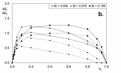
In Figure 5 some results are shown for a fixed Ste (Ste = 0.012), for three different power ratio (W = 2, 4 and 8), and for three different Biot numbers (Bi = 0.059, 0.078 and 0.156). The values of the dimensionless amplitude of total, DE, and latent, DEL, energy are shown as a function of the dimensionless time ratio, t2. The solid line is used for the dimensionless amplitude of the total energy, DE, the dot-dash line for the dimensionless amplitude of the latent energy, DEL. The dimensionless amplitude of total and latent energy is zero for t2 =0 (steady heating with a low power) and for t2 = 1 (steady heating with a high power). Both distributions show a maximum in the interval 0 < t2 < 1.
Figure 5. Dimensionless amplitude of total, DE (¾), and latent, DEL (---), energy for Ste = 0.012, as a function of t2; a.: W = 2; b. W = 4; c. W = 8
For increasing values of W, the maximum of DEL tends to move towards low values of t2 when Bi decreases. This is due to the fact that the latent term is able to give a significant contribution to the energy storage just for short durations of the high power heating (Fig. 3). For higher values of Bi, the sensible term is as high as to be prevailing over the latent one, in particular for high values of t2. For longer durations of the high power heating, low values of Bi mean low external heat transfer and thence a lower variation of energy storage, because the system tends to stay in the solid phase S2.
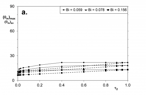
Figure 6. Maximum, (qm)max (¾), and average, (qm)av (- -), dimensionless mean temperature, for Ste = 0.012, as a function of t2; a.: W = 2; b. W = 4; c. W = 8
The maximum amplitude of the total energy variation is well evident for low values of W; this maximum increases for increasing values of W. Conversely, for high values of W, the distributions tend to become flat, and independent of t2. This is mainly due to the latent term, which tends to be very efficient (DEL ≈ 1), with the maximum possible contribution in terms of charge and discharge of the thermal storage. For the highest value of W the distributions of the amplitude of dimensionless total energy storage are quite independent of Bi. In this range of W the two components, sensible and latent, of the energy storage seem to compensate their effects. A low Bi means a high temperature and a high sensible contribution; conversely, a high Bi means a low temperature and a high latent contribution.
For the same values of Ste, Bi and W of Fig. 5, in Fig. 6 is shown the maximum, (qm)max, and the average, (qm)av, dimensionless mean temperature on the heated surface as a function of the dimensionless time t2.
The distributions of (qm)max are characterized by a growing trend for increasing values of W, the opposite for increasing values of Bi. This reflects that a high energy input during a period (high W), coupled to a constant “intensity” of the ambient heat transfer (same Bi), is the reason of an increase of the temperature. Conversely, a better heat transfer due to larger surfaces of the fins in air or a more intensive convection (high Bi), coupled to the same energy input (same W), is the reason of a decrease of the temperature.
For the whole set of data shown in Fig. 6, for increasing values of t2 a value of (qm)max independent of the value of t2 is rapidly reached; this is exactly the value of the high power steady state reached for t2 = 1.
The distributions of (qm)av , for increasing values of t2 , are characterized by a linear increase between the values corresponding to the low and high power steady heating, This average temperature is clearly related to the dimensionless input energy into the system, equal to:
$\Pi=\Pi_{1}\left[1-(\Omega-1) \tau_{2}\right]$ (36)
where:
\Pi=\frac{q_{1} t_{1}+q_{2} t_{2}}{\left(\Delta H_{L}\right)_{\max }} (37)
\Pi_{1}=\Pi\left(t_{1}=P, t_{2}=0\right)=\frac{q_{1} P}{\left(\Delta H_{L}\right)_{\max }} (38)
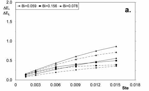
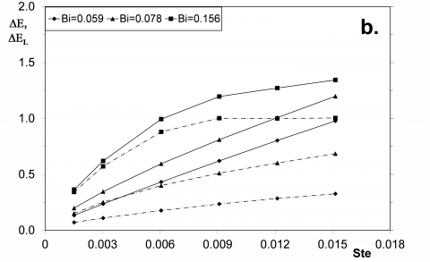
In Figure 7 some results are shown of the amplitude of the dimensionless total, DE, and latent, DEL, energy storage as a function of the Stefan number, Ste, for t2 = 0.6 and for three Biot numbers, Bi = 0.059, 0.078 and 0.156. The solid line is used for the amplitude of dimensionless total energy, DE, the dashed one for the amplitude of dimensionless latent energy, DEL. For the whole set of calculations, DE increases with Ste and with W. Differently, DEL tends to a constant value for increasing values of Bi. This constant value, for increasing values of W, tends to its limiting value, DEL = 1, occurring when the change of phase is extended to the whole volume filled by the PCM. This situation occurs only for contemporary high values of Bi, W and Ste. This means that at high values of W and Ste, a large fin able of a good heat transfer with the ambient (high Bi) is helpful for the exploitation of the PCM in the TCU. However, it also means that, from a certain point, the system is unable to take advantage of the phase change process. Going deeply into the process, for the chosen value of t2, during the time of high power input (Fig. 3), high values of W and Ste favour the complete phase transition and the consequent energy storage. During the time of low power input, a high value of Bi facilitates the complete release of the stored latent energy (see for an example, Fig. 4). In these cases, the storage of total energy is significantly linked to that of latent energy. This behaviour explains Fig. 7.a, where a high Bi (Bi = 0.156) inhibit the phase change of the whole volume filled by the PCM and a further increase of latent storage is not possible. This behaviour explains also Fig. 7.c, where for Bi = 0.156 the distribution of DE crosses that of Bi = 0.059 and 0.078. For Bi = 0.156 the whole volume filled by the PCM changes its phase and a further increase of latent storage is not possible.
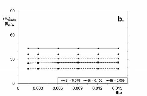
For the same values of t2, Bi and W of Fig. 7, in Fig. 8 is shown the maximum, (qm)max, and the average, (qm)av, dimensionless mean temperature on the heated surface as a function of the Stefan number, Ste. Both (qm)max and (qm)av are quite independent of Ste, though they strongly increase with W. The effect of Bi is such that the dimensionless temperature decreases with Bi. The decrease is larger for larger values of W. When combining the results of Figure 7 and 8, it is confirmed that efficient fins help to ensure low values of the maximum dimensionless mean temperature on the surface exposed to the heat flux, coupled to a good exploitations of the phase change process.
Figure 7. Dimensionless amplitude of total, DE (¾), and latent, DEL (- - -), energy for t2 = 0.6, as a function of Ste; a.: W = 2; b. W = 4; c. W = 8
Figure 8. Maximum, (qm)max (¾), and average, (qm)av (- -), dimensionless mean temperature on the heated surface, for t2 = 0.6, as a function of Ste; a.: W = 2; b. W = 4; c. W = 8
A TCU with a PCM energy storage system, designed for the thermal control of electronic devices, has been investigated numerically. Conduction heat transfer is the prevailing heat transfer process. The application is characterized by a periodic heating on two levels of power.
The analysis of the energy behaviour of the system shows that the storage of energy varies periodically in time with the two levels of the heating boundary condition.
The main design parameter is the maximum value of the mean temperature on the heated surface, where the electronic components to be cooled are placed.
In general it can be observed that a TCU based on PCM is suitable to be used when a high power heating acts in short times. During the peak of heating, the phase change can occur; afterwards, it is important that the storage system could release the stored energy in a freezing process.
For this hybrid heat storage system, in order to exploit the presence of the PCM, it is important to store and to release an amount of latent energy lower than the maximum latent energy storable.
Since the dimensionless parameters governing the steady periodic process are thirteen, we concentrated our attention on two parameters useful to describe the thermal load (W and t1) and on two more parameters useful to characterize the thermal behaviour of the TCU (Bi and Ste).
When W is low, a high value of Bi helps to control the temperature, but the contribute of the PCM can be very low, because the most of the energy input during the high power heating phase is dissipated in the ambient. In the opposite case, when W is high, a low value of Bi is not enough to avoid a sensible heating of the TCU, protracted also after the complete phase-change of the PCM. In this situation the TCU is not useful for the control of temperature.
A complete exploitation of the PCM requires therefore an accurate design of the system on the base of the parameters affecting the performance of the TCU.
The technical and financial support of ELENOS Srl is gratefully acknowledged.
|
Symbol |
||
|
B |
m |
Thickness of the basement |
|
Bi |
|
Biot number (he*L)/lF |
|
c |
J/(kg K) |
Specific heat at constant pressure |
|
Fo |
|
Fourier number aFP/L2 |
|
$h_{e}^{*}$ |
W/m2K |
Equivalent heat transfer coefficient |
|
H |
J/m3 |
Specific enthalpy |
|
L |
J/kg |
Enthalpy |
|
P |
s |
Period |
|
q |
W/m2 |
Heating power |
|
r |
J/kg |
Latent heat of fusion |
|
Ste |
|
Stefan number cS1TR/r |
|
t |
s |
Time |
|
T |
K |
Temperature |
|
TR |
K |
Reference temperature q1L/lF |
|
w |
m |
Thickness of the fin |
|
W |
m |
Half width of the fin-PCM system |
|
x |
m |
Cartesian coordinate |
|
X |
m |
Solid-solid interface position |
|
y |
m |
Cartesian coordinate |
|
Greek symbols |
||
|
a |
m2/s |
Thermal diffusivity |
|
ASi |
|
Thermal diffusivity ratio aSi/aF |
|
E |
|
Dimensionless energy DH/(DHL)max |
|
h |
|
Dimensionless coordinate x/L |
|
q |
|
Dimensionless temperature (T-T0)/TR |
|
l |
W/(m·K) |
Thermal conductivity |
|
LSi |
|
Thermal conductivity ratio lSi/lF |
|
x |
|
Dimensionless coordinate y/L |
|
X |
|
Dimensionless position of the interface X/L |
|
r |
kg/m3 |
Density |
|
P |
|
Dimensionless input of energy qt/(DHL)max |
|
t |
|
Dimensionless time t/P |
|
ti |
|
Time ratio ti/P |
|
W |
|
Power ratio q2/q1 |
|
Subscripts |
||
|
a |
|
Ambient |
|
av |
|
Average over a period |
|
B |
|
Basement |
|
f |
|
Phase change |
|
F |
|
Fin |
|
m |
|
Mean on the heated surface |
|
max |
|
Maximum |
|
min |
|
Minimum |
|
L |
|
Latent |
|
PCM |
|
Phase change material |
|
S1, S2 |
|
Different phases of the solid PCM |
|
W |
|
Half width of the fin-PCM system |
|
0 |
|
Initial condition |
|
1, 2 |
|
Low and high power |
1. Sharma, V.V. Tyagi, C.R. Chen and D. Buddhi, “Review on thermal energy storage with phase change materials and applications” Renewable and Sustainable Energy Reviews, vol. 13, pp. 318-345, 2009. DOI: 10.1016/j.rser. 2007.10.005.
2. E.M. Alawadhi and C.H. Amon, “PCM Thermal control unit for portable electronic devices: experimental and numerical studies,” IEEE Trans. Components and Packaging Technologies, vol. 26, pp. 116-125, 2003. DOI: 10. 1109/TCAPT.2003.811480.
3. F.L. Tan and C.P. Tso, “Cooling of mobile electronic devices using phase change materials,” Applied Thermal Engineering, vol. 24, pp. 159-169, 2004. DOI: 10.1016/j. applthermaleng.2003.09.005.
4. R. Kandasamy, X.Q. Wang and A.S. Mujumdar, “Application of phase change materials in thermal management of electronics,” Applied Thermal Engineering, vol. 27, pp. 2822-2832, 2007. DOI: 10.1016/j. applthermaleng. 2006. 12.013.
5. L. Fan, J.M. Khodadadi, “Thermal conductivity enhancement of phase change materials for thermal energy storage: a review,” Renewable and Sustainable Energy Reviews, vol. 15, pp. 24-46, 2011. DOI: 10.1016/j.rser.2010.08. 007.
6. N. Sarier, E. Onder, “Organic phase change materials and their textile applications: an overview,” Thermochimica Acta, vol. 540, pp. 7-60, 2012. DOI: 10.1016/j.tca.2012. 04.013.
7. P. Lamberg, R. Lehtiniemi and A.M. Henel, “Numerical and experimental investigation of melting and freezing processes in phase change material storage,” Int. J. Thermal Sciences, vol. 43, pp. 277-287, 2004. DOI: 10.1016/j. ijthermalsci.2003.07.001.
8. R. Kandasamy, X.Q. Wang and A.S. Mujumdar, “Transient cooling of electronics using phase change material (PCM)-based heat sinks,” Applied Thermal Engineering, 28 1047-1057, 2008. DOI: 10.1016/j.applthermaleng.2007.06.010.
9. X.Q. Wang, C. Yap and A.S. Mujumdar, “A parametric study of phase change material (PCM)-based heat sinks,” Int. J. Thermal Sciences, vol. 47, pp. 1055-1068, 2008. DOI: 10. 1016/j.ijthermalsci.2007.07.016.
10. S. C. Fok, W. Shen and F.L. Tan, “Cooling of portable hand-held electronic devices using phase change materials in finned heat sinks,” Int. J. Thermal Sciences, vol. 49, pp. 109-117, 2010. DOI: 10.1016/j.ijthermalsci.2009.06. 011.
11. R. Baby and C. Balaji, “Experimental investigation on phase change material based finned heat sinks for electronic equipment cooling,” Int. J. Heat and Mass Transfer, vol. 55, pp. 1642-1649, 2012. DOI: 10.1016/j.ijheatmasstransfer.2011.11.020.
12. P. Gauché, W. Xu, “Modeling phase change material in electronics using CFD – A case study,” Proc. Int. Conf. on High-Density Interconnect and System Packaging, pp. 402-407, 2000.
13. S. Krishnan, S.V. Garimella, S.S. Kang, “A novel hybrid heat sink using phase change materials for transient thermal management of electronics,” IEEE Trans. Components and Packaging Technologies, vol. 28, pp. 281-289, 2005. DOI: 10.1109/ITHERM.2004.1319190.
14. Stupar, U. Drofenik and J.W. Kolar, “Application of phase change materials for low duty cycle high peak load power supplies,” Proc. 6th International Conference on Integrated Power Electronics Systems, Nuremberg (D), 16-18 March 2010, pp. 1-11.
15. C.H. Son and J.H. Morehouse, “Thermal conductivity enhancement of solid-solid phase-change materials for thermal storage,” J. Thermophysics, vol. 5, pp. 122-124, 1991. DOI: 10.2514/3.237.
16. N. Zheng and R.A. Wirtz, “A hybrid thermal energy storage device, Part 1: design methodology,” ASME J. Electronic Packaging, vol. 126, pp. 1-7, 2004. DOI: 10.1115/1. 1646419.
17. N. Zheng and R.A. Wirtz, “A hybrid thermal energy storage device, Part 2: thermal performance figures of merit,” ASME J. Electronic Packaging, vol. 126, pp. 8-13, 2004. DOI: 10.1115/1.1646420.
18. G. Casano and S. Piva, “Experimental and numerical investigation of a phase change energy storage system”Journal of Physics Conference Series,” vol. 501, pp. 012012, 2014. DOI: 10.1088/1742-6596/501/1/012012.
19. M.N. Ozisik, Heat conduction, J. Wiley & S, New York, 1993.
20. M. Pinelli, G. Casano and S. Piva, “Solid-liquid phasechange heat transfer in a vertical cylinder heated from above,” Int. J. Heat and Technology, vol. 18, pp. 61-67, 2000.