OPEN ACCESS
The characteristics of a jet flow are analyzed. A rotating cone water jet is formed by using plus adding a special spiral section on the basis of research at home and abroad. According to the structural characteristics of the spiral groove, combined with the characteristics of the nozzle and requirements, a spin and nozzle structure is designed which has a spiral groove with certain parameters. A rotating conical water jet is thereby obtained. The force is analyzed in a high pressure pipe and fluid while spinning, and these are analyzed for the contraction in the force of the abrasive particles and the force of the fluid leaving the jet nozzle. The movement characteristics of the particles are understood as fluid in the jet formation process, which provides data support for further study for adding abrasive particles. A trajectory equation of the rotating cone water jet is derived based on the characteristics of the fluid movement, focusing on the actual movement of the fluid. The movement characteristics and mechanical properties of the fluid in a nozzle are also analyzed. The influence of nozzle structure parameters on the formation of the jet is obtained through experimental study. This shows that the cross section of the ring or circle diameter D correspondingly decreases with the increase of pitch H, and the inner diameter D essentially remains unchanged. The section shape of the basis is a circle with a center hole with a diameter of 2 mm. The brightness of the section with the hole is inferior to the condition of the one without a hole. The increasing trend of circle diameter D is more than that of the inner diameter D as the nozzle diameter di increases. These are the theoretical and experimental foundations for further optimizing spinning structures.
Water jet technology for cleaning, descaling, cutting, drilling and crushing has been developed around the world, becoming part of the rise of new technologies and new processes [1][2].
A rotating water jet is defined as a diffusion jet which is formed under the condition of a non-rotating nozzle with three-dimensional velocity and formed by jet liquid along a spiral path. An abrasive water jet is formed by the abrasive particles in the jet. It will help to improve the make-up and enhance the performance of the jet nozzle, and contribute to studies on the theoretical analysis and structural parameters of fluids in a rotating conical abrasive water jet nozzle, and has great theoretical value.
There are many works of research about the water jet at home and abroad. Kinik, Daniel et al. have designed an on-line monitoring system for cutting technology through an abrasive water jet. The experiments were conducted with four different settings of the traverse speed of the cutting head [1]. Feng, Fuping et al. made a non-retention model through analysis of the mechanism for displacing fluid elements. Several rules were deduced on the basis of the calculation results: the retention range of the drilling fluid decreased gradually on the casing and well walls as the casing eccentricity increased, and the retention degree in the annular narrow gap became more severe [2]. Kohorst, Philipp et al. investigated the machining of human dentine using an abrasive water jet and evaluated the influence of different abrasives and water pressures on the removal rate [3]. Jiang, Yu-Ying et al. investigated the dynamic characteristics of multiphase flow and discovered that they are further improved by adding polyacrylamide into the pre-mixed abrasive water jet (AWJ), where the multiphase flow in an abrasive suspension jet (ASJ) nozzle is simulated based on a Cross equation[4]. Batikh, Ahmad et al. presented a numerical analysis of the behavior of synthetic jets with a sub-millimetric (mini jet) and micrometric (micro jet) dimensions, conducted with the CFD code Fluent [5]. Huang, Zhongwei et al. presented the experimental results of perforation with AWJs under ambient pressures to simulate practical conditions, and designed a new container that is able to stand 20 MPa in order to lay the casing and natural limestone samples [6][7]. Ibraheem, Hussein Mohammed Aliassess et al. assessed the influence of abrasive water jet machining parameters on the hole-making process of woven-laminated GFRP material to find the optimum values of the process parameters [8]. Ojbai, Arko et al. obtained an improvement in the predictive accuracy and capability of generalization capable of being achieved by the ELM approach in comparison with GP and ANN. Kalpana, K.et al. worked on the principles of erosion of material by the action of a high velocity water jet mixed with abrasive particles and air. The input parameters involved in the AWJM system were water jet pressure, abrasive flow rate, orifice diameter, nozzle diameter, particle size of the abrasive, abrasive type, and related factors [9][10].
Water jet nozzle design is very important, as it directly affects the shape and performance of the jet. The methods of formation for the rotating water jet are as follows: tangential injection method, fixed blade rotating method, tubes, and mechanical rotation method [11] [12]. A rotating conical abrasive water jet nozzle consists of a liquid pipe, rotating groove part, conical contraction parts and nozzle. The rotating groove part lies between the conical contraction parts and the liquid pipe, and connects them. An abrasive slurry flows from the high pressure rubber pipe via the pipe joint to the liquid pipe, and forms a spiral movement after entering the flow slot and center hole because of a rotary pieces barrier. The spinning part is a special component with a spiral channel, which is divided into two types, one without and one with a center hole. The abrasive slurry is fed through the rotating groove part and rotated into the conical contraction parts through a hole contraction cone angle of 30 ° as a spiral flow. The fluid dynamic effects of abrasive slurry are enhanced after the conical contraction, which gives the slurry a higher rotation speed. The speed of the abrasive slurry is further accelerated in the nozzle, which forms a rotating conical abrasive water jet after leaving the nozzle. Figure 1 shows a structural diagram of the nozzle head [13].
Figure 1. Schematic of nozzle of rotating conical abrasive jet
Ⅰconical contraction parts II - rotating groove part
III - liquid pipe
1 - rotating conical abrasive jet 2 - nozzle 3 - nozzle pressure cap
4 - nozzle body 5 – spinning parts 6- center hole
3.1 Stress analysis of mixed fluids in a high pressure pipeline
For a liquid-solid two-phase flow system, with high velocities (3 m/s or more), thin and medium solid particles are in a completely suspended state [14]. Abrasive (sand) in the fluid is mainly loaded by the viscous force, gravity Q and the resistance T of the rigid wall. The principal stress of the abrasive in the high pressure pipeline has a force of thrust upwards, with wall friction resistance T1, and the collision force between sand and sand. The mixture is loaded from wall friction T2 and pump pressure P. For the abrasive itself, the particles must overcome a certain resistance and need to consume corresponding energy to achieve a certain speed and acceleration according to the two phase flow principle. This energy passes to the particles through the turbulent diffusion mechanism of the water media. At the same time, the distribution of particle concentration in any section of the flow or port also depends on the turbulent diffusion because a two-phase medium has solid phase concentration.
3.2 Stress analysis of fluid in rotating groove part
As the mixture flows through the spinning part, if the spinning part has no hole, the fluid is forced to enter the spiral
channels in a spiral flow, and the time stress of the mixed fluid has fluid dynamic pressure F, gravity Q, friction T1, friction resistance T2 of rotating groove part, and pressure difference △P2 before and after entering the spiral channels. When mixed fluid is in a normal flow state, the stress in the rotating groove part has inertia P, fluid dynamic pressure F, gravity Q and friction force T. The first two fluid forces play the main role. If the rotating groove part has a center hole, with a larger diameter such as 3-4 mm or more,, then when the mixed fluid flows into the top of the rotating groove part, the stress of the mixed fluid has a fluid dynamic pressure F, gravity Q, friction T1, resistance T2 of the rotating groove part and pressure difference △P 2 for before and after the spiral channels resistance, and pressure difference △P1 for before and after the central hole. Note that the stresses are the same in addition to △P1, △P2 for the fluid. Because the center hole is larger, the value of the stress caused by △P1 and △P2 is similar, and the direction is perpendicular to the fluid surface and points in the opposite direction to the advance fluid, but the size of its value is still △P1>△P2.
So most fluid arising from the stress caused by △P2 and under comprehensive stress enters the rotating channels with a spiral movement, and there is a small part of the fluid injection from the center hole under the comprehensive force caused by △P1 and others. When the mixed fluid is in a normal flow state, the fluid is forced by the stress into a spiral channel: inertia P, fluid dynamic pressure F and gravity Q, and the friction force T, the fluid stress in the center hole has a fluid dynamic pressure F, gravity Q and friction stress T, with the fluid dynamic pressure F playing the main role. The spinning part of the center hole has a smaller diameter of 2mm or less, due to the pressure difference △P1≥△P2 between the internal and external. Other comprehensive stress easily overcomes the stress caused by △P2, while the stress made by fluid injection from the holes is much smaller than the total stress forcing liquid into the spiral channels (stress of making fluid rotary motion). Thus the mixed fluid under comprehensive stress including the fluid dynamic pressure almost enters all the spiral channels and does not emerge from the hole, but is spread into a conical shape through the injection.
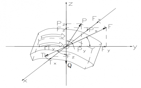
When mixed fluid in a spiral channels, the moving characteristics of abrasive and water in spiral channels are different, position and velocity of mixed fluid in the cross section area of the different section are not the same. The current state in the inside is laminar move, the flow velocity to increase gradually, and flow pattern gradually convert to the turbulent flow. Its characteristics are the interaction result of stress of nature, size, and the role direction. Abrasive stress have inertial P, gravity Q, and friction T, fluid dynamic pressure F etc, which is for smaller abrasive particles, the role of gravity Q is small. For simplifying the complexity research of abrasive particle dynamics, we assume that stress analysis of a particle at a moment in a position is shown in figure 2, which establish the three dimensional space coordinate system, and ox axis perpendicular to the spiral channels side to the level of paper, oy axis represents level in the direction of cutting fluid, oz axis represents the vertical upwards [15] [16].
(1) Fluid dynamic pressure
Because movement speed of water is faster than that of abrasive particle, abrasive particles is loaded hydrodynamic pressure F.
Figure 2. Stress analysis of abrasive particles
In the turbulent state, the fluid dynamic pressure calculation formula is:
F=ψ (U-V) 2d2Δ
Type: ψ-resistance coefficient; U-flow velocity (m/s); V-abrasive particle velocity (m/s); d-the diameter of the abrasive particles (m); Δ-liquid density (kg/m3)
In laminar, calculation formula of particles under the fluid dynamic pressure of water:
F=3πdμ (U-V) Δ
Type: μ-viscous coefficient;
The basic flow velocity of layer depends on its depth of position, fluid dynamic pressure of the abrasive particles depend on the height and movement speed of water layer. The role direction of the fluid dynamic pressure abrasive particles decides in the water flow layer position [4].
In order to facilitate research, the fluid dynamic pressure F is decomposed in three coordinate system of space, namely Fx, Fy, Fz; Fx to make the particles moving along the spiral channels, Fy to convey particles movement forward, Fz to make the particles rising. Fluid dynamic pressure in different locations have different direction, making the particles movement trend to the direction in different area.The force generated by pulse of mixed fluid can make the particles movement. Integrated force by the pulse of turbulent and Fz make abrasive particles floating in the state.
(2) Gravity
For an abrasive particle, its gravity is the same, and direction is for the vertical downward, such as the quality of particles for m, gravity Q equal to mg. If smaller particles, the effect of gravity can be ignored.
(3) Inertia centrifugal force
When tracking along the spiral curve, particles produce inertia centrifugal force, which size is relevant on particles quality m, movement speed v and track curvature 1 / ρ, computation formula is: P = mv2 / ρ. If the proportion of different size particles is different and quality is same, and particles have different movement speed, then inertia centrifugal force of particle is different. Large particles are more, and then the fluid dynamic pressure and flow velocity are also bigger.
(4) Friction
When particle collide spiral channels, friction can be produced, its direction instead of grain direction, size and location is different because of colliding the wall of the channel, formula for T = fN, N for integrate force of inertial centrifugal and law force of fluid dynamic pressure, f for friction coefficient.
3.3 Stress analysis of abrasive particles within the contraction
Mixed fluid of abrasive and water passing the high-pressure pipeline get a certain speed, then the spin movement along rotation part, into the conical contraction parts. Because the conical contraction shape, the internal energy form of fluid will change: part of the static pressure gradually translate into dynamic pressure, the high pressure water to further speed up. So abrasive and water speed become imbalanced, thus making the abrasive particles again getting up, but the speed of abrasive particles less than the speed of water flow. The force of the abrasive in the stage: inertial centrifugal force P, gravity Q, wall friction T, fluid dynamic pressure F. But friction numerical is less than that of rotation part, and direction is always opposite to the granular movement direction, and the values of inertia centrifugal force P and fluid dynamic pressure F increase accordingly, the size and the direction of gravity Q are unchanged, analysis of fluid dynamic pressure F and inertia centrifugal force P is similar to rotation part..
3.4 Stress analysis of the fluid from the nozzle
The mixed fluid makes a rotating movement after leaving the nozzle in a very short time because of inertia. Experiments prove that the turbulence intensity of the rotation flow is smaller than that of the water flow in a straight line, and the track of mixed fluid particles is a spiral. For the whole of the mixed fluid loaded by gravity and inertia centrifugal force, the fluid spreads in a movement caused by the centrifugal force and forward front continuously, and thus it forms a unique horn shape from the exterior. Abrasive particles also form a certain spread in advancing, focused on the role of the fluid dynamic pressure, but also affected by gravity Q and inertia centrifugal force P. In time, the circle radius of the fluid spiral movement increases gradually, and the momentum of the jet will be passed to the gas at the same time; thus the centrifugal force becomes smaller and the fluid speed gradually decreases, and the corresponding fluid energy also slowly decreases.
The mixed fluid in the spiral channels flows spirally through stress analysis in the nozzle and performance analysis. Taking a single particle of fluid as an example, its movement track is similar to a spiral line according to the coordinate system in Figure 2. The cylindrical coordinates in the equation are:
$x=r \cos \theta, z=r \sin \theta, \quad y=\frac{H}{2 \pi} \theta$ or $y=r \theta \operatorname{tg} \alpha$
Among them $r$ - the radius of a spinning part; $0 \leq \theta \leq 2 \pi$ ; $\alpha$ - a add corner of spinning part; $0 \leq \alpha \leq \frac{\pi}{2}$ .
If you know two random coordinates of fluid in the space, space coordinates of the other may be calculated, the specific calculation methods are as follows:
$\left(x_{3}, z_{3}, y_{3}\right)=\left|\begin{array}{ccc}i & j & k \\ x_{1} & z_{1} & y_{1} \\ x_{2} & z_{2} & y_{2}\end{array}\right|$ = $\left|\begin{array}{ccc}i & j & k \\ r_{1} \cos \theta_{1} & r_{1} \sin \theta_{1} & \frac{H}{2 \pi} \theta_{1} \\ r_{2} \cos \theta_{2} & r_{2} \cos \theta_{2} & \frac{H}{2 \pi} \theta_{2}\end{array}\right|$ = $\left|\begin{array}{ll}r_{1} \sin \theta_{1} & \frac{H}{2 \pi} \theta_{1} \\ r_{2} \cos \theta_{2} & \frac{H}{2 \pi} \theta_{2}\end{array}\right|i $ - $\left|\begin{array}{ll}r_{1} \cos \theta_{1} & \frac{H}{2 \pi} \theta_{1} \\ r_{2} \cos \theta_{2} & \frac{H}{2 \pi} \theta_{2}\end{array}\right|j$ + $\left|\begin{array}{ll}r_{1} \cos \theta_{1} & r_{1} \sin \theta_{1} \\ r_{2} \cos \theta_{2} & r_{2} \cos \theta_{2}\end{array}\right|k$
For analysis movement and track characteristics of fluid, mixed fluid can be thought as a single medium, so the complexity of motion have greatly simplified. Because a spiral movement of particle can form spirals line and spiral movement form the corresponding spiral face, then the helicoid can be calculated by integral. If the plane vertical to axis of spiral face cut spiral face, and contour line of face is gotten, its polar equation is as follows:
r_{k}=r(\phi) \cos \phi i+r(\phi) \sin \phi j
The above contour line for spiral movement to be spiral surface, its equation is as follows:
$r_{m}=M r_{k}$
$M=\left|\begin{array}{cccc}\cos \delta & -\sin \delta & 0 & 0 \\ \sin \delta & \cos \delta & 0 & 0 \\ 0 & 0 & 1 & p \delta \\ 0 & 0 & 0 & 1\end{array}\right|$
Among them P is spiral parameters, axial displacement quantity of turned 1 radian.
$p=\frac{H}{2 \pi}$ , $\delta$is the angle of turn.
The equation of spiral face is:
$r_{m}=r(\phi) \cos (\phi+\delta) i+r(\phi) \sin (\phi+\delta) j+p \delta k$
The equation of helix by integral: $r=\int_{r_{1}}^{x} r_{m} d r(\phi)$ .
From the above analysis, we can conclude that each fluid point from the rotating conical abrasive jet has a three-dimensional speed, and the particle track forms a spiral. High-speed fluid particles with a three-dimensional speed impact on the materials, not only with a positive pressure, exerting a radial “extend” force and a circular “cut” force. This is preferable to an ordinary jet sample on the material effect through the positive impact of broken rock. So rotating conical abrasive jet pressure on the material radial is in the form of an “extend” force and a circular “cut” force, plus the positive impact force, and it will be easy to meet or exceed the corresponding strength of the materials, which produces material destruction through stretch and shear, greatly improving the crushing efficiency [17] [18].
The following analysis demonstrates that the influence of the drilling is affected by the center and size of the hole of the spinning part. When there is no center hole, the analysis of the breaking and drilling mechanism is as above. When there is a center hole, then two potential scenarios present themselves: firstly, when the center hole has a diameter smaller than 2 mm, at the beginning, because the jet gets to the front of the spinning part, the internal and external pressure difference of the central hole far outweighs the pressure difference using spiral channels. Then the force caused by other comprehensive forces overcomes the pressure difference, and the fluid flows relatively easily in a spiral channel. So the jet from the center hole almost fails to shoot, other than by the spiral movement that proceeds from the spiral channels, and then accelerates by conical contraction again through the nozzle forming rotating conical jet. This type of mechanism for a breaking and drilling jet is the same as that of one without center holes.
Secondly, when there is a large center hole with a diameter of 3 mm or more, with the increase of the size of the hole, the pressure difference inside and outside the center hole decreases, gradually equaling the pressure difference from the spiral channels. So there are parts of the jet which have a pressure difference injecting from the center hole. The tiny injection from the nozzle has a great effect in directing the flow onto the materials drilling. At the same time there is part of the jet along the spiral channels that becomes a rotating conical abrasive jet, which plays an important role in drilling. In this case, smaller convex cones will appear in the center in theory, as the experimental results demonstrate. Because the rotating conical abrasive jet erodes broken material at the same time, the small flow at the center has a direct role in gradually eroding and striking convex cones, making the convex cones smaller, even almost invisible.
5.1 Influence on the shape of the jet of spin pitch and center holes
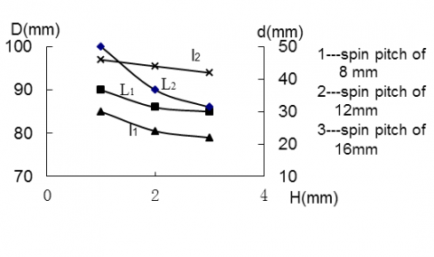
Because the experimental effects of a single head are poorer, two head spins were selected for the experiment. The experimental conditions were as follows: two head spins, spin pitches of 8 mm, 12 mm, and 16 mm, a nozzle diameter of 2.00 mm, a cone contract angle of 30 °, working pressure of 8 Mpa, a work target of 80 mm, and impacting time of 7 seconds. The experiment data was as follows:
Figure 3.The influence trend figure of section shape of jet by spin pitch
The linear regression analysis of curve in the figure:
L1: $D=1.5 H^{2}-8.5 H+97$
L2: $D=3 H^{2}-19 H+116$
l1: $d=-4 H+33$
l2: $d=-2 H+48$
That can be concluded by the analysis of above data and curve trend in figure:
(1) For the spinning part of the same head, the effect of the spin pitch was small. With the increase of spin pitch H, the section shape remained the same, but the outside diameter D of the section circle was reduced, and the inner diameter D remained basically unchanged, so the influence on the outer diameter was clear. Because the spin pitch increased, the rising angles of the spiral channels became bigger under equal a length of material, and the spin degree was lesser, which
made the rotation of the jet poorer, and the tangential velocity and radial velocity also smaller. If the rising angles were too big, the jet approximated a direct flow and the jet had almost no tangential velocity, thereby decreasing the section diameter.
(2) When the center hole diameter of the spinning part was 2 mm, the shape of the section was basically circular. When the center had no holes, the shape of the section was a torus. The diameter of the circle or torus of the former compared to the latter, under the same conditions, was smaller by about 10 mm, and the width of the torus accordingly increased and its brightness was less than that of one without center holes. Concrete analysis is as follows: when the spinning part has no center holes, the mixed flow tends to spin, caused by the resistance of the spin and spiral channels in existence when the mixed flow reaches the front end of the spinning part. The mixed flow is forced into the spiral channels flowing out to form a spiral movement, and then through conical contraction acceleration out through the nozzle almost in the form of a standard hollow cone shape, so the shape of the jet section is a torus. Almost all the energy of the jet is on the thickness of the periphery, which has relatively concentrated energy, and the brightness of torus is stronger, and the circle diameter D is bigger. When the diameter of the center hole of the spinning part is 2mm, the stress of the mixed flow becomes more complex after reaching the front end of the spinning part, and the mixed flow is mainly affected by comprehensive functions such as the fluid dynamic pressure, spin resistance and the internal and external pressures of central hole, which in turn are mainly affected by the influence of the resistance-producing flow trend caused by rotation. The mixed flow is affected by the axial force of fluid dynamic pressure and the internal and external pressure difference of the central hole, which enables a mixed flow to emerge through the center hole. Because the diameter of the hole is smaller, the pressure difference of the center hole between the internal and external is smaller, and the sum of the axial force of fluid dynamic pressure and pressure difference inside and outside the center hole is less than the resistance of the spin. Thus the mixed flow has a rotating trend, almost all flowing out from the spiral channels, but not from the center hole. The jet momentum is thus smaller, and part of the energy is less than that of the energy from a nozzle without center holes or spin. Because the whole process accords with energy and momentum conservation, the tangential velocity of the jet through the nozzle is small, namely degrees small; the radial velocity and the diameter of circle are small and the thickness of the cone is bigger under the same conditions, namely the width of the torus on the cross is bigger, which causes the energy to disperse, and the brightness of the torus is less than that from one without center holes [19] [20].
5.2 Influence to section shape of jet by nozzle diameter
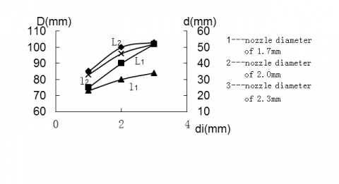
Experimental conditions: spinning part of respectively two head and three head, pitch of 8 mm, nozzle diameter of 1.7 mm and 2.0 mm and 2.3 mm, conical contract angle of 30 °, working pressure of 8 Mpa, work target of 80 mm, work time of 7 seconds. The drawing of experimental data is as follows:
Figure 4. The influence trend figure of section shape of jet by nozzle diameter
The linear regression analysis of curve in the figure:
L1: $D=-6 d_{i}^{2}+33 d_{i}+58$
L2: $D=-6 d_{i}^{2}+33 d_{i}+58$
l1: $d=-1.5 d_{i}^{2}+11.5 d_{i}+13$
l2: $d=-3.5 d_{i}^{2}+23.5 x+13$
That can be concluded by the analysis of above curve in figure: With nozzle diameter increases, section shape remain unchanged, but the size of torus increase, the increase trend of outer diameter D are more than that of inner diameter d, increasing range of two head of spinning part is more than that of three head. Because the nozzle diameter increases, the amount of mixed flow are increased in the same period, and direction of tangential velocity of fluid particles of the vents is changed, shoot angle β is increased, which make diameter of section increasing in the same target.
The structural characteristics of a rotating conical abrasive jet and the results of the drilling experiment are comprehensively analyzed. Its mechanism and process reveal a more complicated process of varying factors. There are tensile elastic damage components caused by jet impact and the erosion function of the material particles, and a “water wedge” role on the materials as well as general broken characteristics of the water jet, and the unique characteristics of shearing and damaging failure to produce a fracture zone of the outer torus. This is formed by two larger free surfaces inside and outside, that then create rock particles for free surface erosion and shear, which easily drop from the main body [21][22]. On the other hand, the flow characteristics of spin forward and rotating outgoing to return of the rotating conical abrasive jet not only reduce the loss of the return resistance of the jet flow, but also strengthen the shear and erosion role of the rock particles of the free surface. This is unique drilling by a rotating conical abrasive jet.
This project is supported by research fund project of Nanjing institute of technology (No. CKJB201201) and the support project of science and technology of Jiangsu Province, China (No. BE2011712), the National Natural Science Fund Project (No.51275227) and the planning project of humanities and social science research fund of the ministry of education (No. 12YJAZH151) and the college fund project of Jiangsu Province, China (No. 10KJB460003) and the youth project of humanities and social science research fund of the ministry of education, China (No. 12YJCZH209) and the open project of key discipline construction of College of Mechanical Engineering in Nanjing Institute of Engineering (No.JXKJ201503).
1. Kinik Daniel, Gánovská Beáta, Hloch Sergej, Monka Peter, Monková Katarína, Hutyrová, “On-line monitoring of technological process of material abrasive water jet cutting,” Zuzana Source: Tehnicki Vjesnik, v 22, n 2, p 351-357, 2015. DOI: 10.17559/TV-20130904111939.
2. Feng Fuping, Ai Chi, Xu Haisu, Cui Zhihua, Gao Changlong, “Research on the condition model of drilling fluid non-retention in eccentric annulus,” Source: International Journal of Heat and Technology, v 33, n 1, p 9-16, 2015.
3. Kohorst Philipp, Tegtmeyer Sven, Biskup Christian, Bach Friedrich-Wilhelm, Stiesch Meike, “Machining human dentin by abrasive water jet drilling,” Source: Bio-Medical Materials and Engineering, v 24, n 2, p 1485-1495, 2014.
4. Jiang Yu-Ying, Gong Lie-Hang, Xu Xin-Lin, Wang You-Cheng, “Numerical simulation of flow field in abrasive water jet nozzles,” Source: Binggong Xuebao/Acta Armamentarii, v 35, n 4, p 461-467, 2014, Language: Chinese.
5. Batikh Ahmad, Caen Robert, Colin Stéphane, Baldas Lucien, Kourta Azeddine, Boisson Henri-Claude, “Numerical and experimental study of micro synthetic jets for flow control,” International Journal of Heat and Technology, v 26, n 1, p 139-145, 2008; ISSN: 03928764; Publisher: Edizioni E.T.S.
6. Zhang Hongshen, Chen Ming, “Theoretical analysis and experimental study on the coating removal from passenger-vehicle plastics for recycling by using water jet technology,” JOM, v 67, n 11, p 2714-2726, May 7, 2015. DOI: 10.1007/s11837-015-1424-6.
7. Huang Zhongwei, Li Gensheng, Shi Huaizhong, Niu Jilei, Song Xianzhi, Shao Shangqi, “Abrasive water jet perforation experiments under ambient pressures,” Atomization and Sprays, v 25, n 7, p 617-627, 2015. DOI: 10.1615/AtomizSpr.2015011050.
8. Ibraheem Hussein Mohammed Ali, Iqbal Asif, Hashemipour Majid, “Numerical optimization of hole making in GFRP composite using abrasive water jet machining process,” Journal of the Chinese Institute of Engineers, Transactions of the Chinese Institute of Engineers, Series A/Chung-kuo Kung Ch’eng Hsuch K’an, v 38, n 1, p 66-76, January 2, 2015. DOI: 10.1080/02533839.2014.953240.
9. Ojbai Arko, Petkovi Dalibor, Shamshirband Shahaboddin, Tong Chong Wen, Ch Sudheer, Jankovi Predrag, Dui Nedeljko, Barali Jelena, “Surface roughness prediction by extreme learning machine constructed with abrasive water jet,” Precision Engineering, March 17, 2015. DOI: 10.1016/j.precisioneng.2015.06.013.
10. Kalpana K., Mythreyi O.V., Kanthababu M., “Review on condition monitoring of Abrasive Water Jet Machining system,” Proceedings of 2015 International Conference on Robotics, Automation, Control and Embedded Systems, RACE 2015, April 28, 2015. DOI: 10.1109/RACE.2015.7097254.
11. Liu Linlin, Sun Zhengcheng, Wan Chuliang, Wu Jimei, “Jet flow field calculation & mechanism analysis on hot-air drying oven based on RNG K-E model,” International Journal of Heat and Technology, v 33, n 1, p 77-82, 2015; ISSN: 03928764; Publisher: Edizioni ETS .
12. Naresh Babu, M., Muthukrishnan, N., “Investigation of multiple process parameters in abrasive water jet machining of tiles,” Journal of the Chinese Institute of Engineers, Transactions of the Chinese Institute of Engineers,Series A/Chung-kuo Kung Ch’eng Hsuch K’an, v 38, n 6, p 692-700, August 18, 2015. DOI: 10.1080/02533839.2015.1010944.
13. Batikh Ahmad, Caen Robert, Colin Stéphane, Baldas Lucien, Kourta Azeddine, Boisson Henri-Claude, “Numerical and experimental study of micro synthetic jets for flow control,” International Journal of Heat and Technology, v 26, n 1, p 139-145, 2008; ISSN: 03928764; Publisher: Edizioni E.T.S.
14. Jerman Marko, Valentini Joko, Lebar Andrej, Orbani Henri, “The study of abrasive water jet cutting front development using a two-dimensional cellular automata model,” Strojniski Vestnik/Journal of Mechanical Engineering, v 61, n 5, p 292-302, 2015. DOI: 10.5545/sv-jme.2014.2179.
15. Liu Xiaohui, Liu Songyong, Ji Huifu, “Numerical research on rock breaking performance of water jet based on SPH,” Powder Technology, v 286, p 181-192, December 2015). DOI: 10.1016/j.powtec.2015.07.044.
16. Ahmed A.B., Hamed M.S., “Modeling of transition boiling under an impinging water jet,” International Journal of Heat and Mass Transfer, v 91, p 1273-1282, December 2015. DOI: 10.1016/j.ijheatmasstransfer.2015.07.130.
17. Bilbao Guillerna, A. Axinte, D., Billingham J., “The linear inverse problem in energy beam processing with an application to abrasive waterjet machining,” International Journal of Machine Tools and Manufacture, v 99, p 34-42, December 2015. DOI: 10.1016/j.ijmachtools.2015.09.006.
18. Sevda Dehkhoda, Michael Hood, Habib Alehossein, David Buttsworth, “Analytical and Experimental Study of Pressure Dynamics in a PulsedWater Jet Device,” Flow Turbulence Combust, 3.29:1-29, 2012.
19. Luo Xiaohui, Cao Shuping, Shi Weijie, He Xiaofeng, “Analysis and design of a water pump with accumulators absorbing pressure pulsation in high-velocity water-jet propulsion system,” Journal of Marine Science and Technology, Volume 20, Issue 3, pp 551-558, September 2015.
20. Yue-Tzu Yang, Yi-Hsien Wang, Jen-Chi Hsu.Numerical thermal analysis and optimization of a water jet impingement cooling with VOF two-phase approach. International Communications in Heat and Mass Transfer,Volume 68, Pages 162–171, November 2015.
21. Wenming Zhang, David Z. Zhu, “Far-field properties of aerated water jets in air,” International Journal of Multiphase Flow, Volume 76, Pages 158–167, November 2015.
22. Amir H. Azimia, Yu Qianb, David Z. Zhu, Nallamuthu Rajaratnamb, “An experimental study of circular sand–water wall jets,” International Journal of Multiphase Flow, Volume 74, Pages 34–44, September 2015.