OPEN ACCESS
A three-dimensional model of cylindrical automobile exhaust thermoelectric generator system is established. The fluid simulation software Fluent is employed to simulate the heat transfer performance of smooth exhaust channel and exhaust channel with fin. The influence of thickness, height and numbers of fins are studied. According to the simulation result and based on pressure drop of the channel, it is found that when the fins are 5mm in thickness, 15mm in height and 16 in number, the channel with such fins is the optimal one. The computing results provide theoretical support for designing the cylindrical automobile exhaust thermoelectric generator system dealing with automobile exhaust.
Simulation Study, Cylindrical Thermoelectric Generation, Automobile Exhaust, Heat transfer characteristics.
Relevant studies show that 60% energy in the automobile fuel is yet to be used. Most of them are released in the atmosphere in the form of waste heat. Energy in the automobile exhaust can account for 30-45% of total fuel heat value[1,2]. Therefore, to generate power by using the waste heat is energy-saving and facilitates the dynamic performance and fuel economy of vehicles. In this way, more oil resources can be saved and less green house gases are emitted, both of which can bring huge social and entomic benefits[3,4].
The cylindrical automobile exhaust thermoelectric generator system uses the seebeck effect to realize a direct transfer from thermal energy to electric energy[5]. At the present, common automobile exhaust thermoelectric generator systems are either flat plate or cylindrical. The flat plate systems are widely applied and have attracted much attention[6]. Though the thermoelectric power generation modules are easy to install, the flat plate system has a negative impact on pressure drop of exhaust, which is adverse to the efficiency[7,8]. The cylindrical system has a higher efficiency and can be integrated with the exhaust silencer so as to reduce backpressure of fluid exhaust. But in order to eliminate noise, the size of the section of exhaust silencer should be increased, which as a result, reduces energy grade. What’s more, the cylindrical system is complicated, posing high demand on manufacturing[9,10]. Many researchers, both home and abroad have studied the cylindrical automobile exhaust thermoelectric generator systems, but few discussed the optimization of such system[11,12]. Consequently, this paper simulates the cylindrical automobile exhaust thermoelectric generator system dealing with automobile exhaust under certain conditions and proposes optimization schemes.
Thermoelectric power generation modules are essential to the power generation system. They are distributed between the exhaust channel and the cooling channel. The power is generated by using the temperature difference between two channels. The high-temperature exhaust released from the engine moves through the exhaust channel in the automobile exhaust thermoelectric generator system. By heating the gas tank in the traditional way of heat convection, the gas tank reaches certain temperature on its surface. The thermoelectric power generation modules deployed on the surface of the gas tank have cool temperature at the other end due to the cooling effect of the cooling channel. Therefore, the temperature difference is formed at two ends of the thermoelectric power generation modules, allowing power output[13-15].
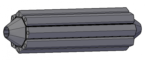
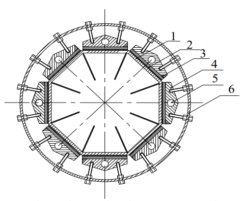
Fig.1 shows the three-dimensional model of cylindrical automobile exhaust thermoelectric generator system. Fig.2 is the section view of the system which consists of octagon exhaust pipe, sleeve, thermoelectric power generation modules, insulation, cooling fin and cooling water jacket. The exhaust pipe is fixed with one plane exposed upward to the air. The mica is fixed against the exhaust pipe, and thermoelectric power generation modules, against the mica, and the insulation, against the power generation modules. The thermal silicone grease is smeared on the contact site. The exhaust pipe is embedded in the supporting barrel and fixed by springs and bolts. There are fins inside the exhaust pipe to boost heat transfer. The whole system is connected to the catalytic reactor and the silencer by flange and lies in between the two.
Figure 1. Three-dimensional model of cylindrical automobile exhaust thermoelectric generator system
exhaust pipe,2 mica,3 thermoelectric power generation components, 4 cooling block,5 cooling pipe,6 supporting barrel
Figure 2. Section view of cylindrical automobile exhaust thermoelectric generator system
As is shown in Fig.2, the fins are distributed evenly along the channel. Their thickness is 3mm,4mm,5mm,6mm and 7mm respectively, their height is 5 mm, 10mm, 15 mm and 20mm, and their numbers are 0(smooth channel), 8 or 16.
The size and structure of the cylindrical automobile exhaust thermoelectric generator system is shown in Fig.3. The total length of TEG is L=945mm. The length of expanded section is L2=80mm. The length of plane where TEM is arranged is L3=685mm. In every plane, 10 TEM are arranged. The inner diameter at the entrance of the exhaust pipe is D=60mm and the external diameter is D1=66mm. The inner diameter of the octagon is 163mm and the external diameter is D2=169mm. The mica is D3=4mm in thickness. The TEM is D4=4mm in thickness. The inner diameter of the cooling pipe is D5=11mm.
Figure 3. Size and structure of the cylindrical automobile exhaust thermoelectric generator system
The fluid flow governing equation is the mathematical form of conservation law. It includes continuity equation, momentum equation and energy equation [16, 17].
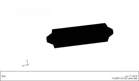
The grid system built is quite adaptive to geometrical structure and flow characteristics of the model, which is beneficial to the dealing with inter-zone coupling conditions of divisional numerical simulation. The total calculation domain is divided into 4119326 hexahedron grid units for the model in this paper.
Figure 4. Grid model
Fundamental assumptions have been made as follows in numerical stimulation. The fluid medium is incompressible fluid featuring steady-state flow; The turbulence model is standard k-E two-equation model; The near-wall region is analyzed by the standard wall function method; The pressure-velocity coupling method is SIMPLE [18]. The inlet boundary condition is set as the velocity inlet boundary condition, with the inlet velocity of exhaust u, defined as $u=60 m / s$, and the turbulence is defined by turbulence intensity and hydraulic diameter; the outlet boundary condition is set as the pressure outlet boundary condition, with the pressure equivalent to the standard atmosphere pressure and without gauge pressure, and the turbulence is also defined by turbulence intensity and hydraulic diameter. As for the surface, its thermal condition is set as convection heat transfer, with the inlet velocity of cooling water v, defined as $v=3 m / s$, and the temperature of 353K; The outlet boundary condition is set as the free stream boundary condition, with the heat transfer coefficient of 5$W / m \cdot K$ [19]. All walls are no-slip, and the heat exchange walls of the solid metal fin and the fluid are set as coupled walls automatically. The physical parameters of materials concerned are shown in Table 1[19], $\rho, \lambda, c_{p}, \mu$ referring to density, thermal conductivity, specific heat capacity, and dynamic viscosity respectively.
Table 1. Parameters of material properties
|
Material |
$\rho$ $\left(k g / m^{3}\right)$ |
$\lambda$ $(W /(m \bullet K))$ |
$c_{p}$ $(J / k g \cdot K)$ |
$\mu$ $(k g / m \cdot s)$ |
|
Exhaust (500℃) |
0.457 |
0.656 |
1185 |
3.48e-5 |
|
Cooling water(80℃) |
965 |
0.68 |
4208 |
3.15e-4 |
|
Exhaust pipe |
7840 |
42 |
465 |
- |
|
Aluminum fin |
2610 |
148 |
904 |
- |
|
Cooling water jacket (Aluminum alloy) |
2710 |
201 |
904 |
- |
|
TEM |
3000 |
2.4 |
250 |
- |
|
Mica |
290 |
0.58 |
2422 |
- |
The temperature field distribution and the velocity field distribution in every structure are obtained through the stimulation of cylindrical thermoelectric generator with smooth exhaust channel and that with exhaust channels with fins on the Fluent software. The velocity of exhaust is average and the temperature is local in the following paragraphs.
5.1 Analysis of the temperature field of the exhaust pipe
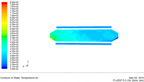
The temperature field distribution of the exhaust pipe without any fin is tabulated in Fig.5. The left end is the exhaust inlet, and the right end is the outlet. The surface temperature of the inlet is high, 683K; in the middle of the pipe where the airflow is relatively steady, the temperature is constant at 572K; and in the end of the pipe, the temperature reduces to 450K due to the cooling water in the cooling fin.
Figure 5. The temperature field of the exhaust pipe
5.2 Comparison between smooth exhaust channels and exhaust channel with fin
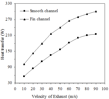
The comparison between the quantity of heat transferred in the smooth exhaust channel and that in the exhaust channel with fin at different flow velocities of exhaust is tabulated in Fig.5. There are 8 fins in an exhaust channel with fin, which are 10 mm high and 5 mm thick. As is shown in Fig. 6, the exhaust channel with fin transfers much more heat, 50 W to 100 W more, than the smooth exhaust channel does. In addition, with the increase of the exhaust flow velocity, the quantity of heat exchanged in the exhaust channel with fin increases from 100 W to 300 W while it increases from 55 W to 215 W in the smooth exhaust channel. From the result, it can be concluded that with the exhaust channel with fin, the hot side temperature of the thermoelectric generating module is nearly 80 °C higher than that with the smooth exhaust channel. Therefore, in the view of heat transfer, the exhaust channel with fin should be used as the heat exchange channel for exhaust.
Figure 6. Variation of heat transfer rate through different channel with Velocity of Exhaust
5.3 The influence of the height of fins on heat transfer capability
The variation of the quantity of heat transferred in channels with the height of fins and flow velocity is tabulated in Fig.6. There are five sizes of fins in height h: 5 mm, 10 mm, 15 mm, and 20 mm, while the thickness is all 5 mm and a channel consists of 8 fins. As what can be seen from Fig.7, the higher the fin, the more heat the exhaust channel with fin transfers; the channel with 15-mm-high fins transfers nearly twice as much heat as 5-mm-high fins. The major reason is the increase of heat transfer area, but when the height exceeds a certain limit, the increase becomes slower[20].
Figure 7. Variation of heat transfer rate through different channel with exhaust flow
The variation of the surface temperature of the heat exchanger with the height of fins and flow velocity is tabulated in Fig.8. It can be seen that when the fin height is fixed, the higher the flow velocity, the higher the surface temperature of the heat exchanger, but the increase of temperature gets slower and slower; when the flow velocity is fixed, the higher the fin, the higher the surface temperature of the heat exchanger. At a low flow velocity, the increase of temperature is quick, but it gets slower as the flow velocity increases. It is because the heat exchange area increases as the fin gets higher, transferring more heat to the surface of the pipe, but the temperature difference between fins and exhaust will be less notable when the height of fins continues increasing, and the heat transfer coefficient will decline; then it will be harder and harder for the exhaust to transfer heat to fins, reducing the work efficiency of fins.
Figure 8. The variation of the surface temperature of the heat exchanger with the height of fins
5.4 The influence of the thickness of fins on heat transfer capability
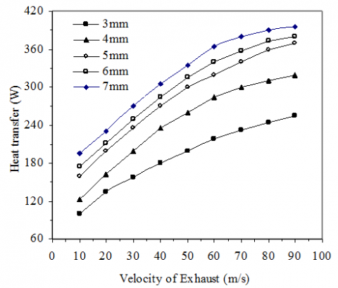
The quantity of heat transferred in channels with fins of different thicknesses and the same height is tabulated in Fig.9. The height h is fixed to 15 mm with 5 sizes of thickness △L: 3 mm, 4 mm, 5 mm, 6 mm, 7 mm. It can be seen that the channel with 3-mm-thick fins transfers much less heat than that with 5-mm-thick fins, while there is not much difference between the quantity of heat transferred in the channel with 5-mm-thick fins and that with 7-mm-thick fins.
Figure 9. Variation of heat transfer rate through different channel with exhaust flow
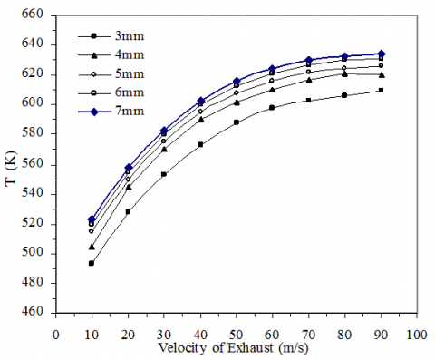
The variation of the surface temperature of the heat exchanger with the thickness of fins and flow velocity is tabulated in Fig.10. It can be seen that when the thickness of fins is fixed, the higher the flow velocity, the higher the surface temperature of the heat exchanger, but when the flow velocity is fixed, the surface temperature of the heat exchanger does not greatly increase as the thickness of fins increases. It is because the heat transfer area only slightly increases as the fin gets thicker while thick fins have very limited influence on the exhaust flow.
Figure 10. The variation of the surface temperature of the heat exchanger with the thickness of fins
5.5 The pressure drop in exhaust channel with fin
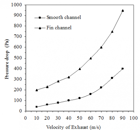
The pressure drop in the smooth exhaust channel and the exhaust channel with fin with different flow velocities is tabulated in Fig.11. Fins in the exhaust channel with fin are 15 mm high and 5 mm thick. It can be seen that when the flow velocity is fixed to 60 m/s, there is a huge difference between the pressure drop in the smooth exhaust channel and in the exhaust channel with fin, since the pressure drop in the smooth exhaust channel is not more than 200 Pa while it exceeds 500 Pa in the exhaust channel with fin.
Figure 11. The pressure drop of different channel
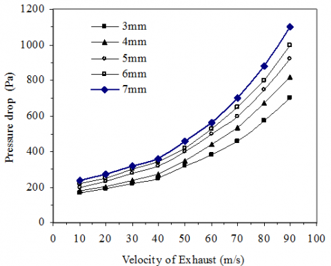
The pressure drop of exhaust with the different heights of fins and flow velocities is shown in Fig.12, and the pressure drop of exhaust with different thicknesses of fins is shown in Fig.13. It can be concluded that at a low flow velocity, the height and thickness of fins almost have no influence on pressure drop, and as the velocity gets higher, the their influence becomes more notable.
Figure 12. The influence of the height of fins on pressure drop
Figure 13. The influence of the thickness of fins on pressure drop
In summary, although the smooth exhaust channel has very small pressure drop, its poor heat transfer capability makes it not suitable for the automobile exhaust thermoelectric generating system. To ensure good heat exchange capability and small pressure drop, the best size of fins is 5 mm in thickness and 15 mm in height.
5.6 The influence of the number of fins on heat exchange capability
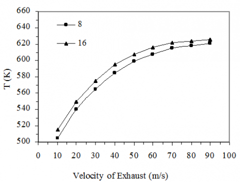
The variation of the surface temperature of the heat exchanger with the number of fins and flow velocity is shown in Fig.14. The number of fins is 8 or 16. It can be seen that the heat exchange efficiency greatly increases as the number of fins increases. When the flow velocity is 40 m/s, the surface temperature of the heat exchanger rises by 5 °C as the number of fins increases from 8 to 16, but when the flow velocity increases, the effect of increasing the surface temperature of the heat exchanger by adding the number of fins is undermined. This is because more fins leaves less space between each other, which makes air hard to flow through, and thus the heat transfer is influenced.
Figure 14. The influence of the number of fins on the surface temperature of the heat exchanger
The variation of the pressure drop of exhaust with the number of fins and flow velocity is shown in Fig.15. It can be seen that at a high flow velocity, the number of fins has a great influence on the pressure drop of exhaust. When the flow velocity is 90 m/s, the pressure drop in the channel with 16 fins is nearly 900 Pa. Considering pressure drop and heat exchange efficiency, the number of fins is finally decided to be 16.
Figure 15. The influence of the number of fins on pressure drop
In this paper, cylindrical automobile exhaust thermoelectric generator system dealing with automobile exhaust is simulated and the following conclusions are reached.
(1) Though the pressure drop of the smooth exhaust channel is small, the heat transfer coefficient is also very low, which is not conductive to generating power by waste heat.
(2) Adding the thickness of fins can enhance the heat transfer efficiency to a small degree. Adding the height of fins can enhance the heat transfer efficiency. When the exhaust moves at a low speed, the efficiency is enhanced greatly. When the exhaust moves at a high speed, the efficiency is enhanced slightly.
(3) The parameters of fins can pose significant influence on pressure drop in exhaust channel. When the exhaust moves at a low speed, adding the thickness and the height of fins would reduce the influence on pressure drop of exhaust. When the exhaust moves at a high speed, adding the thickness and the height of fins would increase pressure drop.
(4) Adding the number of fins can enhance the heat transfer efficiency, but pressure drop of exhaust as well. Therefore, the cylindrical automobile exhaust thermoelectric generator system with octagon channel and 16 fins is the best choice.
This project was supported by Hunan education department Foundation under Project 14K087, China, and by the science and technology office of Hunan Foundation under Project 2014ZK3094, China.
1. GRANDEUR D, CRANE S and HUNG B, Automotive waste heat conversion to electric power using skutterudite, TAGS, PbTe and BiTe, Thermoelectrics, vol. 25, pp. 343-348, 2006.
2. Ikoma K, Munekiyo M, and Furuya K, Thermoelectric module and generator for gasoline vehicles, Thermoelectric Proceeding ICT 98, Nagoya, IEEE Press, pp. 464-467, 1998.
3. XU Lizhen, LI Yan, YANG Zhi and CHEN Changhe, Experimental study of thermoelectric generation from automobile exhaust, J Tsinghua Univ (Sci & Tech), vol. 50, pp. 287-289, 2010.
4. LON E B, Cooling, heating, generating power and recovering waste heat with thermoelectric systems, Science, vol. 322, pp. 413-418, 2008.
5. Zhang X D, Chau K T and Chan C C, Overview of thermoelectric generation for hybrid vehecles, Journal of Asian Electric Vehicles, vol. 6, pp. 1119-1124, 2008.
6. Byung Chul Woo and Hee Wong Lee, Relation between electric power and temperature difference for thermoelectric generation, International Journal of Modern Physics B, vol. 17, pp. 1421-1426, 2003.
7. DENU Yadong, YIN Shu-e, ZHAN Weiwei and SU Chuqi, Analysis of thermal distribution in an automotive exhaust-based thermoelectric generator, Engineering Journal of Wuhan University, vol. 47, no. 1, pp. 115-119, 2014.
8. Yank Shuangliang, Zhang Hone and Xu Hui, Numeric simulation research on heat transfer characteristics of thermoelectric generation device for automobile, Cryo.& Supercond, vol. 39, no. 5, pp. 47-52, 2011.
9. Yuan Xiaohong, Research on Thermoelectric technology of Thermoelectric Generation for Automobile Engine Waste Heat, Ph.D. thesis, Wuhan University of Technology, Hubei, Wuhan., 2012.
10. Zhang Zheng, Xie Xiaopeng and Luo Yutao, Research on the Novel High-intensity Thermoelectric Gnerator and Its Application on HEV, International Conference on Thermoelectric, Institute of Electrical and Electronics Engineers Inc, pp. 517-520, 2005.
11. DU Zhuo-cheng and PENG Jiang-ying, On Cylindrical Heat Exchanger of Automobile Exhaust Thermoelectric Generator, Measurement and control technology, vol. 33, no. 5, pp. 135-138, 2014.
12. RING Haobin, FAN Wen, WANG Jiguan and LU Lei, Study on Heat Dissipation of Thermoelectric Module in Thermoelectric Generation from Automobile Exhaust, Automobile parts, vol. 4, no. 9, pp. 67-71, 2011.
13. NUWAYHID R Y, ROWE D M and MIN G, Low cost stove top thermoelectric generator from regions with unreliable eletricity supply, Renewalbe Enregy, vol. 28, pp. 205-220, 2003.
14. ROWE D M, Thermoelectrics: anenvironmentally-friendly source of electrical power, Renewalbe Enregy, vol. 16, pp. 1251-1256, 1999.
15. CRANE T, GRANDEUR J M and HARRIS L E B, Preformance results of a high power density thermoelectric generator: beyond the couple, BSST LLC, vol. 24, pp. 170-174, 2005.
16. Jin Peng, Research on Thermoelectric Technology for Vehicle Exhaust Waste Heat and Simulation Application, Ph.D. thesis, Jilin University, Jilin, Chang Chun., 2011.
17. Jiang Fan and huang Peng, Advanced application and instance analysis of FLUENT, Beijing, Tsinghua Universitypress, 2008.
18. Sun Qiang, Automobile Waste Heat Thermoelectric Generator Flow Analysis and Optimization Based on Computational Fluid Dynamics, Ph.D. thesis, Wuhan University of Technology, Hubei, Wuhan., 2012.
19. Zhang Yiaodan, Research a cylindrical Thermoelectric Generating System of Vehicle Exhaust Gases, Ph.D. thesis, South China University of Technology, Guang Dong, Guang Zhou., 2011.
20. Liu Zhanbin, Numerical Simulation and Experimental Research of Heat Transfer Process of Fin Tube, Ph.D. thesis, Xi'an University of Technology, Shaanxi, Xi'an., 2008.