Viacheslav Okhrimenko* | Marina Glebova
© 2020 IIETA. This article is published by IIETA and is licensed under the CC BY 4.0 license (http://creativecommons.org/licenses/by/4.0/).
OPEN ACCESS
Much attention is paid to problem of reducing losses of electric energy in electric power industry of many countries, especially in Ukraine. Distribution networks of industrial enterprises in Ukraine are characterized by two voltage levels - 0.4 and 10 kV. Active power factor of industrial power consumers is determined by nature of process and many electrical installations have low cosφ values. Significant flows of reactive power and, as a result, additional irrational losses of electric energy take place in the distribution networks of enterprises as a result. Purpose of this article is to improve methodology of design justification for selection of main elements of internal power supply system of industrial enterprise to obtain rational compensation of reactive power in distribution network of enterprise. Existing methodology for designing a reactive power compensation system involves use of averaged indicators of unit cost of power equipment (transformers, compensating devices) and is based on assumption of linear nature of dependence of these indicators on power of equipment. Study of these dependencies for equipment of number of manufacturers showed their nonlinear character that is not formalized. Article proposes methodology for selecting number and power of compensating devices at same time as power transformers of workshop substations according to criterion of minimum annual reduced costs for these power supply system elements at design stage of power supply system. Proposed method takes into account real cost of power equipment, which can be used in reactive power compensation system at designed enterprise and provides choice of option that meets technical requirements of regulatory documents and has a minimum annual cost.
compensation, loss of electrical energy, reactive power, reduced costs
One of the factors determining the effectiveness of the power supply systems and power consumption systems functioning are reactive power levels in the network elements that directly affect the loss of electrical energy.
In the scientific literature, constant attention is paid to the issues of reactive power (RP) compensation, especially to the methods of RP compensation calculating modes [1, 2], to the analysis of RP compensation tools and systems [3-5], to the methods for selecting devices to compensate RP [6, 7], to the best compensation ways and methods [8-10] and, of course, to the features of RP compensation problems in networks of industrial enterprises [11, 12].
Industrial enterprises are characterized by certain volumes of reactive power consumption exceeding the economically acceptable values of its transmission through power supply companies’ electric networks. It is important that the task of the reactive power compensation level determining is initially solved at the design stage of the industrial enterprise power supply system development. The requirements and recommendations of regulatory documents are taken into account (in Ukraine [13-15]).
The changes that have occurred in the technical and economic indicators of the industrial enterprises power supply systems equipment necessitate their analysis and methodology refinement for design calculations of reactive power compensation systems.
All the design calculations to determine the rational level of reactive power compensation in the networks of industrial enterprises are carried out by means of the method that provides selecting transformers for workshop substation transformer simultaneously with low-voltage and high-voltage reactive power compensation batteries [13-15]. Thus, the criterion for choosing the optimal solution is the minimum reduced costs for the power supply system elements, the cost indicators of which are obtained from the average statistical data on the specific costs of power equipment and the specific cost of electrical energy losses.
The criterion of the minimum annual reduced costs for the reactive power compensation system gives a design solution in which rational flows of reactive power (minimal loss of electric energy) are in the distribution network of the enterprise. The calculation of the reduced costs on the basis of data on the unit cost of electrical equipment (power transformers, low-voltage 0.4 kV and high-voltage 10 kV capacitor banks) does not provide the required accuracy due to the large error of these data.
In the process of designing the industrial enterprise power supply system, the enterprise electric loads calculating problem is initially solved, namely, the average design active Рa.d., reactive Qa.d. and apparent Sa.d. power of the workshop loads for the maximally busy shift are determined. These loads and the enterprise master plan become the initial data for solving the problem of the number and power of workshop substations transformers determining, as well as the number and power of capacitor banks for RP compensation. The selection criterion when considering options is the reduced cost (costs recalculated for the year of operation) of the power supply system.
We need to note that at this design stage, the following elements of the industrial enterprise power supply system, are considered: the workshop substations transformers, low-voltage capacitor banks (LCB) for reactive power compensation, cable lines of the high-voltage (6, 10 or 20 kV) enterprise distribution network, high-voltage plant electrical receivers, high-voltage capacitor banks (HCB) for reactive power compensation. Among high-voltage power receivers, the power of synchronous motors (QSM) is being specified, which can be used to compensate the reactive power.
The calculation procedure is regulated by regulatory documents [13-15] and is set out in RTM 36.18.32.6-92 [13]. The RP compensation means choice as well as the compensating devices power selection is carried out in two stages: when RP is consumed from the power system within the economic value and when RP consumption from the power system exceeds the economic value.
At the first stage, the power of LCB installed in the network up to 1 kV is determined by the criterion for choosing the minimum number of workshop transformer substations, then the synchronous motors’ RP is determined, which is economically feasible to use for RP compensation in comparison with the consumption from the power system, not exceeding the economic value [13]. The economically optimal number of workshop transformers (or group of workshops) Nopt. and LCB power are determined by the unit cost of reactive power transfer through the workshop transformers, taking into account the constant capital costs components (average reduced costs for the LCB and workshop substation transformers).
It is necessary to note that upon completion of the first stage calculations, a balance sheet of RP is compiled at the border of the balance demarcation with the power system. In the case of RP imbalance, the second stage is carried out, in which it is considered economically feasible to obtain additional RP by increasing the capacity of the LCB, making more complete use of the RP generated by synchronous motors by comparing these sources’ power with the RP consumption from the power system exceeding the economic value. At the second stage of calculations, the feasibility of HCB installing in the high-voltage distribution network of the enterprise [13] is also determined.
Power equipment, for each option accepted for consideration, must satisfy the regulatory requirements for technical parameters [16]. Transformers of workshop substations must satisfy the load factor in normal and post- accident conditions; cable section – according to the long-term permissible current in normal and post-accident conditions, by permissible voltage losses, by resistance to short-circuit currents.
Thus, in this work, the options under consideration are compared at the reduced costs, for the calculation of which statistical data are used for the specific costs of reactive power that is consumed in the enterprise network and on the specific losses for the reactive power transfer through the enterprise distribution network.
Reduced costs (capital reduced to year of operation and current annual) for the options under consideration are calculated according to different indicators. As part of capital expenditures, the costs of transformers of shop substations, LCB, HCB and cable lines 10 (6) kV are considered. The current expenses include amortization payouts for power equipment, the cost of electricity losses in workshop substation transformers and in cable lines, and operating expenses as well.
The option with lower reduced costs is accepted for implementation.
This approach to design calculations for selecting the power of transformers of workshop substations, LCB and HCB was developed in the 1960s and subsequently finalized in the beginning of the 1990s in the statistics conditions at that time on specific costs and specific losses in the supply systems’ power elements.
As experience shows, the current stage of many countries’ development is characterized both by technological progress and the dynamics of electrical equipment technical and economic indicators, as well as by sporadic crisis phenomena, which is also the Ukrainian economy characteristic. As a result, accounting for unit costs for the transmission of electric energy and accounting for the averaged reduced costs for capacitor banks and transformers of workshop substations can’t be determined with the required accuracy. In addition, it should be noted that the technical and economic characteristics (cost, guaranteed lifetime, etc.) of the same equipment from different manufacturers are very divers.
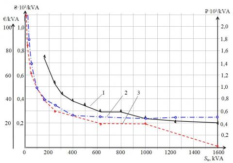
As an example, Figure 1 shows the LCB (0.4 kV) unit cost dependence on the battery power in the production of manufacturers: 1 - LTD “Novotelektro”, Kharkiv [17], 2 - LTD “NKU”, Kiev [18], 3 - CYDESA, Spain [19]. And Figure 2 respectively shows the dependence of the same type power transformers’ unit cost of their rated power from manufacturers: 1 - Schneider Electric [20]; 2 – LTD “Elektropostavka” [21]; 3 - Transformer Service LTD [22].
An analysis of the graphs presented in our work (Figure 1 and Figure 2) clearly shows the nonlinear nature of the equipment unit costs dependence on the equipment’s capacity, as well as the certain complexity of these dependencies’ formal description. The use of average unit costs gives an unacceptable calculation error.
It is necessary to say that another factor which impedes the given costs’ correct calculation is the lifetime of the equipment. So, for example, for capacitor units of the company FRAKO (Germany), the distributor [17] in the specifications announces the estimated service life of 11 – 23 years. However, according to current researches, the consequence of this claimed large dispersion in the normative lifetime of the main means will cause a significant difference in the calculated values of capital costs and the amount of depreciation.
Figure 1. Unit cost of LCB: 1 – LTD “Novotechelektro”, ₴/kvar; 2 – LTD “NKU”, ₴/kvar; 3 – Cydesa, € /kvar
Figure 2. Unit cost of transformers: 1 – Schneider Electric, €/kVA; 2 – LTD “Elektropostavka”, ₽·103/kVA; 3 – LTD“Transformatorservis”, ₴·103/kVA
So, the goal of this research work is to clarify the methodology for determining the number and power of transformers of workshop substations, low and high-voltage capacitor banks, which makes it possible to take into account the real cost of equipment and cost of electrical energy losses.
The proposed methodology for RP compensation designing is characterized by the fact that at the same time, calculations are carried out to determine the number and power of transformers of workshop substations, the number and power of LCB and HCB, and the cable lines cross-section of the enterprise high-voltage distribution network. Calculations are performed for technically acceptable power options for transformers, LCBs, HCBs and cross-sections of cable lines. The options take into account the real cost of equipment from various manufacturers and the cost of electric power losses. For implementation, an option is accepted with minimal reduced costs for a reactive power compensation system.
Among the main design tasks for the reactive power compensation system, the following are distinguished: defining of the workshop transformers’ number and power; defining of the LCB and HCB number and capacity; determination of the RP generated by synchronous motors; and the enterprise high-voltage distribution networks’ cable line cross section defining.
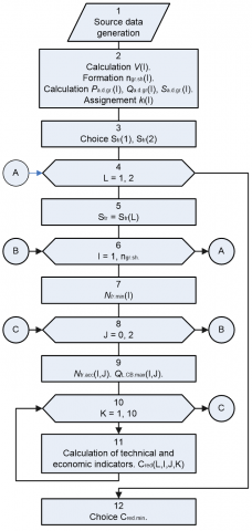
An algorithm for solving the RP compensation system design problem is shown in Figure 3.
Figure 3. Algorithm for solving the reactive power compensation system design problem
Action 1. The massifs of initial data for solving the RP compensation system development problem are formed according to the main results of solving the enterprise electrical loads calculating design problem. For workshop consumers with voltages of less than 1 kV (I correspond to the serial number of the workshop): where nsh – number of workshops; F(I) – workshop area, m2; average design powers of shop consumers active Рa.d.(I), (kW), reactive Qa.d.(I), (kvar) and apparent Sa.d.(I), (kVA); reactive power coefficients tgφ(I) average in the enterprise workshops. For workshop consumers with voltages of more than 1 kV (J corresponds to the serial number of the high voltage power receiver): rated active Рh-v.r.(J), (kW), reactive Qh-v.r.(J), (kvar) power of high-voltage power receivers. Disposable reactive QSM(K) (kvar) high-voltage synchronous motors’ power (K corresponds to the serial number of the high-voltage synchronous motor).
Action 2.
Action 2.1. Making the specific workshops’ electrical loads density calculation in the enterprise V(I) (kVA/m2)
$V(\mathrm{I})=\frac{S_{\mathrm{a.d.}}(\mathrm{I})}{F(\mathrm{I})}$. (1)
Action 2.2. Analysis of the obtained values of workshops’ electrical loads density and determination of preliminary power of workshop transformers Str. according to the criterion of specific density of workshop loads.
Standards [13-15] recommend that with a load density of up to 0.2 kV∙A/m2 choose transformers with a power of 1000 or 1600 kV∙A, with a load density of 0.2–0.5 kV∙A/m2 – with a power of 1600 kV∙A, and at load density of more than 0.5 kV∙A/m2 – with a power of 1600 or 2500 kV∙A.
The decision on the choice of transformer power for a particular workshop of the enterprise is made by the designer taking into account other recommendations: the reliability category of the workshop’s electrical consumers, the minimum number of transformer sizes, the forecast load growth in the future, etc.
In the case of strong discrepancies in the values of the specific capacities of the shops of the enterprise, the integration of closely located shops into groups is performed in order to reduce the spread in the values of specific densities of the load. There formed ngr.sh. of workshops’ groups and the consumers’ capacity of each one in those groups Рa.d.gr.(I), Qa.d.gr.(I) and Sa.d.gr.(I) was calculated.
Based on the regulatory requirements for the consumer reliability category in the workshops of the enterprise, the desired values of the load factors kl.(I) of the workshop transformers are set.
Action 3. Several options of indicated capacities for workshop transformers of the vehicle can be taken into consideration. So, Figure 3 shows us a two options’ algorithm for power transformers, for example, the 1st option – Str(1) = 630 kVA and the 2nd option – Str(2)= 1000 kVA. For this case, all further technical and economic calculations are performed first for the transformers with power 630 кВА, then for a power of 1000 kVA, respectively.
Action 4. The cycle is set with variable L.
Action 5. Power of transformers of workshops Str(L) is selected.
Action 6. The cycle is set with variable I (cycle of workshops groups ngr.sh).
Action 7. For each workshop (group of workshops) the minimum number of transformers Ntr.min.(I) is calculated [13] (where I – workshop or group of workshops serial number)
$N_{\mathrm{tp}, \min }(\mathrm{I})=\frac{P_{\mathrm{a}. \mathrm{d} . \mathrm{gr}}(\mathrm{I})}{k_{1}(\mathrm{I}) \cdot S_{\mathrm{tp}}(\mathrm{I})}$, (2)
and, afterwards, it is rounded to the nearest whole number.
Action 8. Then, a cycle is set out with the variable J (an internal cycle for the variable I).
Action 9. The accepted number of workshop transformers in the group is determined.
Ntr.acc.(I) = Ntr.min(I,J) + J, (3)
where, J – is the additional number of transformers.
It is important to note that in fact, three options are actually being considered: 1st option – the workshop transformers’ minimum number; 2nd option – minimum number plus one transformer; 3rd option – plus two transformers.
For each of the workshop transformers’ number options in the group accepted for consideration, the highest reactive power of the LCB is determined
QLCB.max(I,J) = Qa.d.gr(I,J) – 0,2·Pa.d.gr(I,J). (4)
Action 10. The cycle is set with variable K is defined inside the cycle according to J.
A number of decisions are considered on choosing the power of the LCB in the range of changing the power of the LCB from QLCB.max(I, J, K) (which is equivalent to almost complete reactive power compensation on the low side of transformers) to QLCB(I, J, K) = 0 (no compensation). At each cycle step in K, the calculation is performed for the accepted power QLCB.acc..
The number of options considered is determined by the number of LCB power ratings in the range up to QLCB.max(I, J, K) and the advisable values of the corresponding transformer load factors. Figure 3 shows us the case of 10 steps in K.
Action 11. Calculation of technical and economic indicators of reactive power compensation system.
Technical indicators include the following.
Action 11.1. Determination of calculating active Pc.tr.h-v.(I, J, K) and reactive Qc.tr.h-v(I, J, K) powers on the high-voltage side workshop transformers, taking into account the losses taking place in transformers
Рc.tr.h-v = Рa.d. + ΔРtr.∙Ntr.acc., (5)
Qc.tr.h-v = Qa.d. + QLCB.acc. + ΔQtr.∙Ntr.acc., (6)
where, ΔРtr. and ΔQtr. – are the losses of active (kW) and reactive (kvar) power in the workshop transformers, determined by the well-known correlations:
ΔPtr.∙= ΔPidling + kl.2·ΔPshort circuit, (7)
where, ΔРidling and ΔРshort circuit – are, respectively, the loss of idling and short circuit (kW), determined by the transformer nameplate data;
kl. – transformer load factor.
ΔQtr = (Iidling∙+ kl.2∙Ushort circuit)∙Str.∙10-2, (8)
where, Iidling and Ushirt circuit − respectively, idling no-load current (%) and short-circuit voltage (%), which should be determined by the transformer rating data;
Str. − transformer power, kVA.
Action 11.2. Based on the recommendations of norms [17], the cross-sections of cable lines of the high-voltage distribution network are determined and the power losses in the cable line are calculated
DРCL = 3 ICL2∙RCL, (9)
DQCL = 3 ICL2∙XCL, (10)
where, RCL and ХCL − respectively active and reactive resistances in high-voltage cable line.
Action 11.3. Total power line losses
$\Delta P_{\text {Lines }}=\sum_{i=1}^{n} \Delta P_{\mathrm{CL} i}$, (11)
$\Delta Q_{\text {Lines }}=\sum_{i=1}^{n} \Delta Q_{\mathrm{CL} i}$. (12)
Action 11.4. Design load on the main substation bus bars
$P_{d .1. m . s .}=\sum_{i=1}^{n_{g r . s h}} P_{c . t r . h-v . i}+\Delta P_{\text {Lines }}$, (13)
${{Q}_{d.l.m.s.}}=\sum\limits_{i=1}^{{{n}_{gr.sh.}}}{{{Q}_{c.tr.h-v.i}}+\Delta {{Q}_{Lines}}-{{Q}_{SM}}}$, (14)
where, QSM − the available power of synchronous motors (set by the initial design data).
Action 11.5. Determination of HCB power. The calculated factor of reactive power on the main substation bus bars
$\operatorname{tg} \varphi_{\mathrm{m.s}}=\frac{\mathrm{Q}_{\mathrm{d} .1 . \mathrm{m.s}}}{\mathrm{P}_{\mathrm{d} . \mathrm{l.m.s}}}$, (15)
Reactive power to compensate high-voltage capacity battery (HCB)
QHCB = Рd.l.m.s∙(tgφm.s. − tgφe.v.), (16)
where, tgφe.v. − reactive power factor economic value, which is set out by the initial design data.
Action 11.6. According to the results of the calculation of technical indicators, economic indicators of the considered options are determined: reduced capital costs Ccapitale reduced (workshop transformers’ cost, LCB and HCB cost, cable lines cost) and current costs Ccurrent (depreciation payouts, cost of electric energy losses, operating costs). Thus, reduced costs Creduced are determined for the options under consideration
Creduced = Ccapitale reduced + Ccurrent. (17)
Thus, the total number of options considered is determined by the following: NS.tr – the number of options for workshop transformers’ power; NN.tr – the number of options for the number of transformers in the workshop; NQ.LCB – the number of options for the LCB power.
Action 12. Of all the options for implementation, the option with the lowest data costs is adopted.
This methodology does not require the use of data on unit costs and allows you to take into account the real current electrical equipment value and electric energy cost in order to select the option with the lowest reduced cost.
1. In the power supply systems’ design calculations, when choosing a multivariate solution, the criterion of minimum reduced costs is used.
2. When designing power supply systems for industrial enterprises, the task of calculating the number and power of transformers of workshop substations is traditionally solved simultaneously with the design of a reactive power compensation system. The result of the design calculation is to find a rational number and power of shop transformers, low-voltage and high-voltage capacitor banks for reactive power compensation.
3. In accordance with current standards, the economic indicators of the power supply system are determined according to the averaged statistical unit costs for power equipment, reactive power transfer through transformers of workshop substations and losses in the distribution enterprise network.
4. Analysis of the specific costs of power electrical equipment showed their non-linear nature. The dependence of the unit costs of power electrical equipment on its power cannot be formalized.
5. An improved methodology for designing a reactive power compensation system at an industrial enterprise is proposed (determining the number and power of shop transformers, low-voltage and high-voltage capacitor banks for reactive power compensation). The advantage of the refined methodology and algorithm for its reaction is the use of real costs for electrical equipment and the calculation of the reduced costs for all technically possible design options for a reactive power compensation system.
The use of data on real, rather than specific, costs of electrical equipment eliminates possible errors in calculating the present value of the options considered.
The economic benefit of the chosen option with the lowest present value is the lower losses of electric energy in comparison with other versions of the reactive power compensation system.
|
C F HCB k LCB LTD N n P Q R RP S V X |
cost area, m2 high-voltage capacitor banks factor low-voltage capacitor banks Limited Trade Development number of transformers in a workshop or in a group of workshops number of workshops or groups of workshops active power, W reactive power, war active resistance, Ω reactive power apparent power, VA specific electrical load density, kVA/m2 reactive resistance, Ω |
|
|
Greek symbols |
||
|
Δ |
losses |
|
|
Subscripts |
||
|
a.d. a.d.gr. CL cap.red. c.tr.h-v d. d.gr. d.l.m.s. e.v. gr.sh h-v. h-v.r. l. LCB LCB.acc. LCB.max m.s. opt. red. SM tr. tr.acc. tr.min |
average design average design group cable line capital reduced calculated transfotmer high-voltage design design group design load main substation economic value group of workshops high-voltage high-voltage rated load low-voltage capacitor bank low-voltage capacitor bank accepted low-voltage capacitor bank maximum main substation optimal reduced synchronous motor transformer transformer accepted transformer minimum |
|
[1] Lin, C.E., Chen, T.C., Huang, C.L. (1989). A real-time calculation method for optimal reactive power compensator. IEEE Transactions on Power Systems, 4(2): 643-652. https://doi.org/10.1109/59.193838
[2] Wysocki, W., Szlosek, M. (2011). Compensation of reactive power as a method for reducing energy losses: on the example of calculations and measurements of load flow through the distribution transformer in one of the polish distribution network. 11th International Conference on Electrical Power Quality and Utilisation, Lisbon, pp. 1-5. https://doi.org/10.1109/EPQU.2011.6128904
[3] Rakesh Singh Lodhi, R.C. (2016). Review on reactive power compensation in short transmission line. International Journal of Engineering and Computer Science, 5(9).
[4] Zajkowski, K. (2018). Reactive power compensation in a threephase power supply system in an electric vehicle charging station. Journal of Mechanical and Energy Engineering, 2(1): 75-84. https://doi.org/10.30464/jmee.2018.2.1.75
[5] Sun, Z., Liang, Q.Y., Luo, P.Q., Zhang, C.F. (2012). Study on reactive automatic compensation system design. Physics Procedia, 24: 211-216. https://doi.org/10.1016/j.phpro.2012.02.032
[6] Águila Téllez, A., López, G., Isaac, I., González J.W. (2018). Optimal reactive power compensation in electrical distribution systems with distributed resources. Review. Heliyon, 4(8): e00746. https://doi.org/10.1016/j.heliyon.2018.e00746
[7] Vorotnikov, I., Mastepanenko, M., Gabrielyan, S., Shunina, A. (2019). Energy estimation of parameters of reactive power compensator for nonlinear loads in steady mode. 18th International Scientific Conference. Engineering for Rural Development, Jelgava, Latvia, pp. 515-520. https://doi.org/10.22616/ERDev2019.18.N086
[8] Kim, S.B., Song, S.H. (2020). A hybrid reactive power control method of distributed generation to mitigate voltage rise in low-voltage grid. Energies, 13(8): 2078. https://doi.org/10.3390/en13082078
[9] Gong, Y., Zhang, K., Pu, Z., Li, X.N., Zuo, X.H., Zhen, J., Teng, S.D. (2017). Reactive power compensation method considering minimum effective reactive power reserve. Article in IOP Conference Series: Materials Science and Engineering, 199: 012059. https://doi.org/10.1088/1757-899X/199/1/012059
[10] Sayenko, Y., Sychenko, V., Liubartsev, V. (2019). Development of methods for optimizing reactive power modes based on neural network technologies. 2019 IEEE 6th International Conference on Energy Smart Systems (ESS), Kyiv, Ukraine, pp. 98-103. https://doi.org/10.1109/ESS.2019.8764220
[11] Samet, H., Parniani, M. (2007). Predictive method for improving SVC speed in electric arc furnace compensation. IEEE Transactions on Power Delivery, 22(1): 732-734. https://doi.org/10.1109/TPWRD.2006.886768
[12] Savenko, Y., Baranenko, T., Kalyuzhniy, D. (2015). Compensation of reactive power in electrical supply systems of large industrial enterprises. Przeglad Elektrotechniczny, 1: 79-82. https://doi.org/10.15199/48.2015.11.22
[13] Ukazaniya po proektirovaniyu ustanovok kompensatsii reaktivnoy moschnosti v elektricheskih setyah obschego naznacheniya promyishlennyih predpriyatiy (RTM 36.18.32.6-92) [Guidelines forthe design of reactive power compensation installations in general-purpose electrical networks of industrial enterprises (RTM 36.18.32.6-92)]. Instruktivnyie i informatsionnyie materialyi po proektirovaniyu elektroustanovok. Moscow: VNIPI ″ Tyazhpromelektroproekt ″, no. 2. pp. 24−53. 1993. https://krm.nku04.com.ua/каталог-укрм/ [in Russian].
[14] Nastanova z proektuvannia system elektropostachannia promyslovykh pidpryiemstv. DSTU-N B V.2.5-80: 2015. [Nastanova s project of the systems of electric distribution of industrial products. DSTU-N B V.2.5-80: 2015]. Kyiv: Minrehion Ukrainy, 2016. http://online.budstandart.com/ua/catalog/doc-page?id_doc=63305 [in Ukrainian].
[15] Proektirovanie elektrosnabzheniya promyishlennyih predpriyatiy. M788-1090. Normyi tehnologicheskogo proektirovaniya (1994). [Design of power supply for industrial enterprises. M788-1090. Norms of technological design]. Moscow. http://www.gostrf.com/normadata/1/4294847/4294847066.pdf [in Russian].
[16] National Electric Code (NEC) (2017). https://www.nfpa.org/NEC/About-the-NEC/Free-online-access-to-the-NEC-and-other-electrical-standards, accessed on Mar. 12, 2020.
[17] Catalog of the company “Novotechelectro”. http://n-tel.com.ua/konds.html, accessed on Mar. 12, 2020.
[18] Catalog of the company NKU. https://krm.nku04.com.ua/каталог-укрм/, accessed on Mar. 12, 2020.
[19] Catalog of the company SYDESA. https://issuu.com/cydesa/docs/cydesa_tarif_201415, accessed on Mar. 12, 2020.
[20] Catalog of the company Schneider Electric. http://www.schneider-spb.ru/trihal-transformatory.html, accessed on Mar. 12, 2020.
[21] Catalog of the company "Electropostavka". https://elektropostavka.ru/price-sil-transformator, accessed on Mar. 12, 2020.
[22] Catalog of the company "Transformer Service LTD". http://atrans.in.ua/hmelnitskij-zavod-transformator-servis/b1/2, accessed on Mar. 12, 2020.