Abdelhak Abdou* | Omar Adib Safer | Tarik Bouchala | Abdelmalik Bendaikha | Bachir Abdelhadi | Amor Guettafi | Azzedine Benoudjit
OPEN ACCESS
It is a challenging task to detect the hidden cracks in multilayer riveted structures in a nondestructive manner. This paper puts forward an eddy current nondestructive method for crack detection in such structures based on the electric conductivity of the rivets. Specifically, an eddy current sensor was designed with a ferrite core coil to evaluate the surface and inner defects of different layers. The magnetic phenomena during the detection process was simulated based on the magnetic potential and the scalar electrical potential, and the magnetic potential vector was solved by finite-element method. The proposed method was compared with the eddy current detection method without considering rivet conductivity through an experiment on a three-layer riveted aluminum structure. The length and position of each defect on each layer were changed in the experiment. The results show that the proposed method achieved better accuracy than the contrastive method, and its sensitivity depends on two issues: the position of the defect relative to the separation of the layers and the length of the defect relative to the length of the rivet head. The research results are of great significance for nondestructive testing of multilayer riveted structures in many fields.
eddy current, multilayer, nondestructive testing, finite element method, riveted structures, hidden cracks
In the aeronautical field, economic constraints tend to increase the lifespan of appliances beyond their first cycle. In this case, for a second or third life cycle, it becomes necessary, for safety reasons, to carry out more thorough wear checks. To ensure maintenance, many non-destructive tests punctuate the aircraft's operating life in order to detect a defect before a critical threshold is reached (Figure 1).
The multilayers structures are widely used in the industries especially in the construction of the aircrafts and the space-crafts; these layers are assembled by riveted operation. The riveting is an assembly of pieces using rivets, the layers have been previously drilled each of a hole allowing the rivet rod to cross the one and the other. It is a definitive assembly, that is to say not removable without destruction of the fastener, under working of the riveted structures, are exposed various exteriors factors such as and low temperature, high pressure and noise vibration, these last product a damages and corrosions, generally these problems located around rivets [1, 2].
Rigorous damage tolerance calculations should take into account not only the size of a defect but also the location of that defect within the examined part, when predicting the lifetime of a component. This is especially true in aircraft structures, which are normally composed of multiple layers, with variable thickness, different materials, etc. For example, depending on the type, distribution and level of stress, a small surface crack might be more critical than a large hidden one [1, 2].
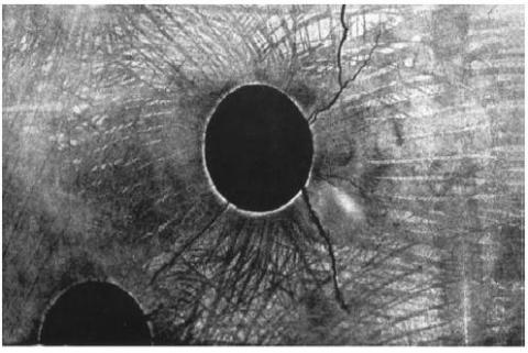
One of the major issues is to control the rivet lines to detect possible cracking phenomena that can be created at the foot or under the rivet propagate given the great mechanical constraints on them. Indeed, the defects present in the riveted structures are born at the bottom of the rivet and grow along the axis of the riveting line. The detection of these defects must be done early before it spreads rivet can cause the lifting of the fuselage during a flight, Figure 2.
One of the most reliable NDT technique is EC method, this method applied in conductive non-magnetic structures, EC method is based on an alternating electromagnetic reaction phenomena between the source who is generate the electromagnetic field and the tested piece who is in approximation with the source field, the electrical reaction of the plate represent in the creation of the eddy currents, the penetration the induced currents depends on skin thickness effect [3-5].
The electromagnetic reaction between the coil and the tested piece give us a state about the geometric properties and the physical properties, in our case the physical properties such as the electrical conductivity is known, otherwise, the induced currents path are closed contours which depends on the geometric state of the tested piece, which is mean that any deformation in the tested piece will effect on the paths of the induced currents although effect on the impedance variation of the eddy current sensor [5-7].
Moreover, the applied eddy current testing in multilayer structures to evaluate the cracks who they will be in the inner layer is low sensitive than the upper layer due to of the skin thickness effect, although eddy current sensor need to be more efficiency with a ferrite core, thus the electromagnetic field produce by the sensor will be more focus in small area, several studies are used magnetic field as a measurement parameter to detect the cracks such as EC-GMR (Giant Magneto-Resistance) [8-10] and EC-Hall effect sensor [11, 12] which they need a special excitation coils (complicated system) in addition rotating electromagnetic field EC-GMR which consist tow printed excitation coils to make a the electromagnetic field to be rotated [13], separated function measurement mode is used in previous works [14], this mode has two coils, one for excitation and the other for pick-up, pulsed eddy current technique used for crack detection in layered structures [15-17], these methods are used for the detection of crack in deep layers with the existing of the rivets, the rivets are electrically conductive which high possibly influence in the quality of detection, to take into account the rivets effect the sensors should be calibrate.
In this paper we are interested in the multilayer structures of riveted conductive plates controlled by an eddy current sensor with a ferrite core, in absolute mode. To highlight the effect of the defects, we propose a study with flaws that are variable from the point of view length with respect to the length of the rivet head (lower and upper) and from the point of view positioning in layers, in addition, the eddy current behavior when two rivets are close from each other. The electromagnetic problem is formulated as magnetic potential vector, finite element method is used as a method of computation for the resolution of the partial derivative equation of the magnetic potential vector to evaluate the imaginary and real part of impedance [11].
Figure 1. Aircraft riveted multilayer structures
Figure 2. Damaged rivet hole
The riveted multilayer structure proposed is a reference in this field, because its geometric and physical characteristics are derived from the sector's real industrial model.
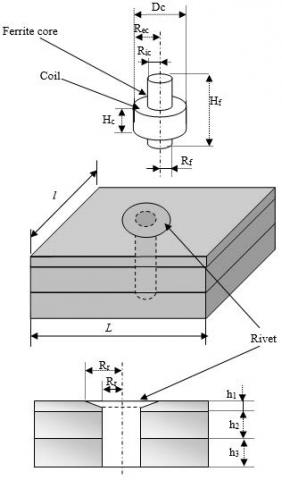
The structure consists of stacked flat plates made of aluminum (homogeneous and non-ferromagnetic and their conductivity varies between 10 MS / m and 30 MS / m), altered or not by a fault, controlled by an eddy current sensor equipped with a ferrite core, in absolute mode, which is as shown in Figure 3.
Figure 3. Problem dimensions
The dimensions of the geometric model can show in table 1.
Table 1. Physical parameters
|
|
Multilayer structure |
Rivet |
Ferrite core coil |
|
Geometrics proprieties |
L= 100 mm l = 70 mm h1= 2.5 mm h3= 4 mm h2= 4 mm |
Rr1= 6 mm Rr2=3.175 mm |
Hf = 8.65 mm Rf = 3.74 mm Hc = 3.46mm Dc = 14.65 mm Ric = 3.74 mm Rec = 7.325 mm Nturn=962 turns |
|
Physical proprieties |
σ= 17e6 (S/m) µr= 1 |
σ=2.34e6 (S/m) µr= 1 |
σ = 60e6 (S/m) (coil) µr =1(coil) µr=1100(ferrite) |
Hc, Dc, Ric, Rec, hf, Rf and Nturn are respectively coil high, wiring diameter, coil internal radius, coil external radius, ferrite high, ferrite coil radius and turns number.
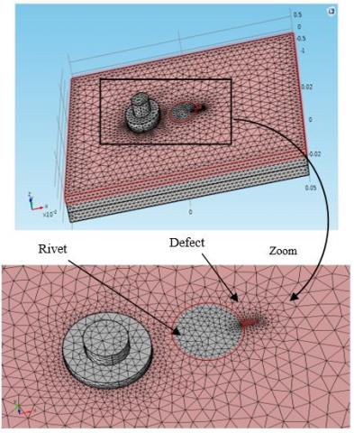
The studied device geometries are as shown in Figure 4.
Figure 4. Problem geometry under COMSOL Multiphysics environment
The next step is mesh generation which based on tetrahedral elements, the quality of the mesh in finite element simulation depend on the number of tetrahedral elements. To obtain an accurate solution with a reasonable computational time the number of elements should be balanced. A fine mesh is required in the region where the variation of the fields is important. In our problem the mesh around the coil should be refine or in the skin depth in the plate since the magnetic induction field varies significantly in these regions. 3D mesh is as shown in Figure 5.
Figure 5. 3D mesh with tetrahedral elements
Induced current are created in tested simple based on the electromagnetic field reaction between the coil and the simple, the electromagnetic phenomena is formulated using A-V formulation approach, A is the magnetic potential and V is the scalar electrical potential, the model regions are divided into five parts, the first is the solenoid coil (inductor), the air region, the three layers of the plate regions which they have the same electrical properties.
$rot\left( \frac{1}{\mu }rot(A) \right)-\left( \frac{1}{\mu }div(grad(A) \right)+j\omega \sigma A+\sigma grad(A)={{J}_{S}}$ (1)
where, A(T/m) is the magnetic potential, σ(S/m) is the electrical conductivity of the multilayer structure, ω is the frequency source (rad/s), μ magnetic permeability of air, and J (A/m2) is the source current.
After resolved the Eq. (1) using FEM, the eddy currents are computed using the following equation:
${{J}_{e}}=-\frac{\partial A}{\partial t}$ (2)
The harmonic magnetodynamic formulation in integral form is obtained by a spatial discretization using the finite element method, which allows in addition to interpolate the unknowns on the elements of the mesh. By applying the Galerkine method and Green's theorem with homogeneous boundary conditions in Eq. (1), we obtain the integral formulation AV-A, defined on the nodes of the mesh of the domain Ω.
$\begin{align} & \int\limits_{\Omega }{\frac{1}{\mu }}rot(A)rot({{N}_{i}})+\int\limits_{\Omega }{\frac{1}{\mu }}div(A)div({{N}_{i}})+ \\ & \int\limits_{\Omega }{j\omega \sigma {{N}_{i}}}(A+gradV)d\Omega ={{N}_{i}}{{J}_{S}}d\Omega \\\end{align}$ (3)
with:
$\int\limits_{\Omega }{j\omega \sigma {{\alpha }_{i}}}grad(A)d\Omega +\int\limits_{\Omega }{j\omega \sigma }grad({{\alpha }_{i}})grad(V)d\Omega =0$ (4)
where, $\alpha_{\mathrm{i}}$ and $\mathrm{N}_{\mathrm{i}}$ respectively are the Scalar projection function and the vector projection function.
The impedance variation of coil is given by:
$\Delta Z=-\frac{j\omega }{{{I}_{0}}}\oint{A\Lambda dl}$ (5)
The real part and the imaginary part of impedance sensor are computed using magnetic potential vector approach such:
$real(Z)=-2\pi \omega {{N}_{turn}}imag(A)$ (6)
$real(Z)=-2\pi \omega {{N}_{turn}}imag(A)$ (7)
We define $\Delta Z$ as the difference between the sensor impedance $Z_{cal}$ when the crack is found in the multilayer plate and the sensor impedance $Z_{c l b}$ using for calibration which taken when the multilayer plate without crack:
$\Delta Z={{Z}_{cal}}-{{Z}_{clb}}$ (8)
To make several calibrations $Z_{\text {clb}}$ we calculate $Z_{\text {clb} 1}$ as sensor impedance without taking into consideration the rivet effect and $Z_{\text {clb2 }}$ as sensor impedance but taking into consideration the rivet effect on the impedance value.
4.1 Induced current
In order to highlight the detection sensitivity of cracks embedded in the multilayer riveted structures, the crack length will be change to be less or equal to the head diameter of the rivet on the one hand , the crack location to be change from layer to another, on the other hand, it is just greater than the outer of the coil diameter (5 mm), and much larger than the latter.
(a) First layer
(b) Second layer
(c) Third layer
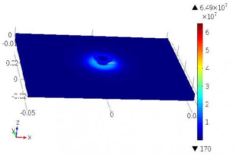
Figure 6. Current density distribution for width defect 5mm (a) first layer, second layer, (c) third layer
The width of the defect, denoted Lad being fixed and equal to 0.2 mm, as for the height it is equal to the height of the layer where the defect is. The lengths of crack used are:
Lod1=1.14 mm, Lod2=2.8 mm, Lod3=5 mm, Lod4= 7.5 mm, Lod5= 10 mm.
In first scan model we suggest the impedance reference which is taken in the case of the sensor is above the multilayer plate without taking into account the rivets effects, this last impedance is compared with sensor impedance taking from the numerical model such as that we move the crack from first layer to the second and so on.
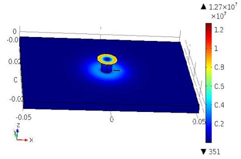
Figure 6 shows the distribution of induced current in layered structure, defects are located in the first layer (a), second layer (b) and third layer (c) with defect length 5 mm.
The Figure 6 shows the current density distribution with different location of defect (a) first layer, (b) the second layer (c) the third layer, the current density penetration is decreasing with so that's the biggest value located on the first layer thus when the presence of the damage in this layer it have a big impact on the sensor impedance compared to if these defects located on the second or the third layer.
4.2 Sensor impedance
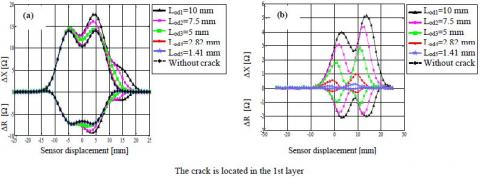
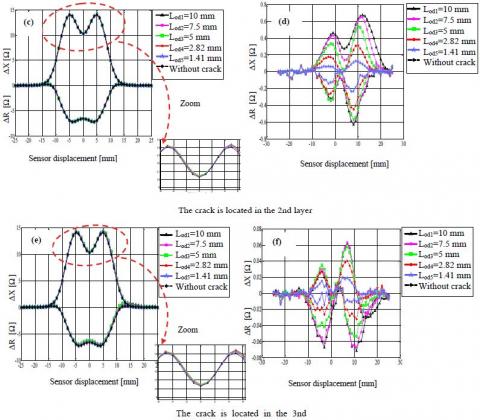
The Figures 7 illustrates the numerical simulation results the ECT for crack is located in the 1st, 2nd and 3rd layers where the calculated impedances are taken without taking into account the rivets effects (a), (c) and (e), the calculated impedance where the rivets effects is taking into consideration in the 1st, 2nd and 3rd layers the sensor response respectively in (b), (d) and (f) the height of crack being that of the layer, it is 2.5 mm.
The curves in Figure 7 illustrate, as a function of the sensor displacement, the imaginary part (ΔX) and the real part (ΔR) of impedance variations. When we use the Zclb1 as calibration in the 1st, 2nd and 3rd layer the sensor responses can be seen that the signals are symmetrical, in the form of "M", only for the case "without crack" where the crack in the 2nd and the 3rd layer as shown in Figure 1(c), (e), which is mean the crack response it is not so visible for lengths less than or equal to the radius of the rivet head, then the right part of the signal increases proportionally with the length of the crack. This dissymmetry is very visible for lengths of 5 mm or more in the case of the crack located in the 1st layer as shown in figure 1(a).
We can also see that in the vicinity of the point "0", which corresponds to the middle of the rivet, the signal varies before the arrival of the sensor itself at the beginning of the crack, this can be explained by the fact that the lines of the sensor reach the beginning of the crack without the sensor being above the crack, hence the sensitivity of the detection. It is shown that the sensor begins to be sensitive to the presence of the crack before approaching it as shown in Figure 7(a).
The signatures of crack in case of Zcalb2 are very clear. It may be noted that, on the one hand, the signals are no longer symmetrical, given the "early" sensitivity of the crack-presence probe, and on the other hand that the variation between crack whose length is less than or equal to rivet heads are now very readable. This readability is explained by the fact that the signal in case of Zcalb2 corresponds to 30% of the previous signals which are signals Zcalb1, it is because of this fact that before the difference is not very visible.
Figure 7. Sensor impedance in 1st, 2nd and 3rd layer for (a), (c) and (e) sensor without take into account the rivet effect; (b), (d) and (f) sensor take into account the rivet effect
In this paper a riveted multilayer structure has been developed with consideration of the nature of the rivet material with a coil provided with a ferrite core. To highlight the sensitivity of the detection, we have chosen different lengths of defects and being alternated on the three layers.
The series of simulations carried out made it possible to conclude that the sensitivity of the detection depends on the one hand, the position of the defect with respect to the separation of the layers of the detection coil, and on the other hand the length of the defect in relation to the length of the rivet head, the sensor calibration based on the chosen impedance which computed when the EC-sensor above the multilayer structure without defect and taken into account the electrical conductivity of the rivet, the computed results show very variation between the two models with and without taking into account the rivet conductivity.
[1] Javier, G.M., Jaime, G.G., Ernesto, V.S. (2011). Non-destructive techniques based on eddy current testing. Sensors Journal, 11(3): 2525-2565. https://doi.org/10.3390/s110302525
[2] Bouzidi, A., Maouche, B., Feliachi, M., Berthiau, G. (2012). Pulsed eddy current non-destructive evaluation based on coupled electromagnetic quantities method. Eur. Phys. J. Appl. Phys., 57(1). https://doi.org/10.1051/epjap/2011100483
[3] Menana, H., Féliachi, M. (2010). Modeling the response of a rotating eddy current sensor for the characterization of carbon fiber reinforced composites. The European Physical Journal Applied Physics, 52(2): https://doi.org/10.1051/epjap/2010079
[4] Abdou, A., Bouchala, T., Benhadda, N., Abdelhadi, B., Benoudjit, A. (2018). Influence of conductive pollution on eddy current sensor signals. Russian Journal of Nondestructive Testing, 54(3): 192-202. https://doi.org/10.1134/S1061830918030026
[5] Naidjate, M., Helifa, B., Feliachi, M., Lefkaier, I.K., Heuer, H., Schulze, M. (2017). A smart eddy current sensor dedicated to the nondestructive evaluation of carbon fibers reinforced polymers. Sensors, 17(9). https://doi.org/10.3390/s17091996
[6] Helifa, B., Féliachi, M., Lefkaier, I.K., Boubenider, F., Zaoui, A., Lagraa, N. (2016). Characterization of surface cracks using eddy current NDT simulation by 3D-FEM and inversion by neural network. ACES Journal, 31(2): 187-194.
[7] Xu, W., Cao, M.S., Ding, K.Q., Radzieński, M., Ostachowicz, W. (2017). Crack identification in CFRP laminated beams using multi-resolution modal teager–kaiser energy under noisy environments. Materials, 10(6): 656. https://doi.org/10.3390/ma10060656
[8] Yang, G., Dib, G., Udpa, L., Tamburrino, A., Udpa, S.S. (2015). Rotating field EC-GMR sensor for crack detection at fastener site in layered structures. IEEE Sensors Journal, 15(1): 463-470. https://doi.org/10.1109/JSEN.2014.2341653
[9] Pasadas, D., Ribeiro, A.L., Ramos, H.G., Rocha, T. (2016). 2D geometry characterization of cracks from ECT image analysis using planar coils and GMR-sensors. In IEEE International Instrumentation and Measurement Technology Conference Proceedings, Taipei, Taiwan, pp. 1-5. https://doi.org/10.1109/I2MTC.2016.7520426
[10] Choua, Y. (2010), Application of the finite element method for the modelization of eddy current non-destructive control configurations. Ph.D. dissertation, University Paris South 11.
[11] Stott, C.A., Underhill, P.R., Babbar, V.K., Krause, T.W. (2015). Pulsed eddy current detection of cracks in multilayer aluminum lap joints. IEEE Sensors Journal, 15(2): 956-962. https://doi.org/10.1109/jsen.2014.2354404
[12] Luo, F.L., Pan, M.C., Weng, F.B., Hu, X.C., Gao, J.Z., Liu, B., He, Y.Z. (2010). Pulsed eddy current technique for defect detection in aircraft riveted structures. NDT&E International, 43(2): 176-181. https://doi.org/10.1016/j.ndteint.2009.10.010
[13] Yang, G., Dib, G., Udpa, L., Tamburrino, A., Udpa, S.S. (2015). Rotating field EC-GMR sensor for crack detection at fastener site in layered structures. IEEE Sensors Journal, 15(1): 463-470. https://doi.org/10.1109/JSEN.2014.2341653
[14] Lepine, B.A., Dubois, J.M.S., Giguère, S.R. (2002). Detection of cracks beneath rivet heads via pulsed eddy current technique. AIP Conference Proceedings, 615(1): 1968-1975. https://doi.org/10.1063/1.1473034
[15] Mandache, C., Tian, G.Y., Abidin, M.M.I.Z. (2009). Pulsed eddy current testing with variable duty cycle on rivet joints. NDT&E International, 42(7): 599-605. https://doi.org/10.1016/j.ndteint.2009.04.001
[16] Javier, G.M., Jaime, G.G., Ernesto, V.S. (2011). Non-destructive techniques based on eddy current testing. Sensors J, 11(3): 2525-2565. https://doi.org/10.3390/s110302525
[17] Knopp, J.S., Aldrin, J.C., Jata, K.V. (2009). Computational methods in eddy current crack detection at fastener sites in multi-layer structures. Nondestr Test Eval, 24(1-2): 103-120. https://doi.org/10.1080/10589750802195519