Abdeldjouad Touahria | Cherif Bougriou*
OPEN ACCESS
The current study focuses on the efficiency of heat emitters (radiators) in the premises. The purpose objective of this study is to investigate an optimal heat transfer between the ambient air and the walls of the radiator to make a birth to a new economic system of ventilation-radiator. A reduced computational domain was numerically studied in (2D) by CFD simulations with FLUENT and (k-e) standard model. Near-wall treatment, a standard Wall-function is applied. Through this study, it was found by an analogy of ventilation-radiator system with a heat pump HP that cold air supply decreases the COP of HP, and therefore increases the energy consumption of heating system (combustible or electricity) and makes it costly and uneconomical. Wherever, elliptical tubes ensure a very high of heat exchange coefficient by convection in cross flow and staggered arrangement tubes. That results in an important COP of installation, with reduced costs, which making the system economical and exploitation costs reasonable. According to the findings of this research, a new economic system of ventilation- radiator system is proposed, which is based on the increase of the heat transfer coefficient by convection (αcon), of the external surface of the radiator by placed elliptical tubes with a cross flow to the radiator, and a heat exchanger at an opening channel in the wall behind, that recover heat from the exhaust hot air discharged to outside, by the fresh air brought from outside. An extension of the external tube of the heat exchanger (used air) is proposed to ensure the correct flow of air brought from outside. The difference of quantity of energy with and without heat exchanger increases simultaneously with outside air temperature which passes through the heat exchanger where it undergoes a preheating by absorbing a quantity of heat from the discharged hot air to outside through the annular passage of the heat exchanger. This quantity of energy is the gain of installation (reduction of the energy consumption necessary for heating), and this heat flux recovered advantage our system over other heating systems. This directly affects the performance of the installation.
cross flow, CFD, COP, economical system, elliptic tubes, heating system, transfer coefficient by convection (αcon), ventilation-radiator
1.1 Background and earlier studies
In the case of ventilation-radiators, the only publications known that touch on this subject are those of Myhren and Holmberg [1-5], but none of these publications treated optimization of convective heat transfer [6]. The focus is on thermal comfort and ventilation rates. The performance of a similar system was described by Elmualim et al. and Mundt et al. [7, 8]. Recently, studies have proposed ventilation as the only important factor in reducing the problems of enclosed areas such as allergy or asthma [9-11], which requires a parallel ventilation system of the heating system in winter periods. Myhren and Holmberg [5] proposed the ventilation of the radiator as a practical solution to this problem. The air in housing premises it must be renewed periodically for hygiene conditions. Thus, the air renewal is used in ventilation-radiator system into the ventilate radiator, which is a combination of ventilation and heating.
Myhren and Holmberg [4, 5] studies show that low-temperature heating systems create an internal climate more stable and uniform, with lower air velocities and weak temperature differences [ 10-12]. With these low temperature systems, internal climate is assumed best to human health than that provided by the high temperature heating systems [13-15]. The study of Shati et al. [16] is very important concerned roughness and emissivity of the wall behind the radiator. The results indicate that heat transfer can be increased by 26 % when using a wall with saw-tooth fins with high emissivity, then with smooth shiny fins, this means that when using a wall behind the radiator with a roughness and emissivity important, this will increase the extraction of heat from the radiator, and the heat exchange is optimal [16].
1.2 Principle of ventilation-radiator system
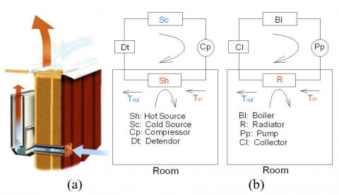
The cold fresh air brought from outside to the room to be heated, enters through an opening channel at the outside wall behind the radiator. It is flowing directly to the radiator where it undergoes a preheating. The temperature difference between the outside air and the radiator is very important than in other heating systems which increasing the coefficient of heat transfer by convection (Heat transfer is optimal when it’s coefficient by convection (αcon) between the air and the walls of the radiator is high, this can be achieved by increasing the inlet temperature of hot water of radiator (Tin) for all cases of type of hot water supply system), this makes the radiator in the ventilation-radiator system more efficient than radiator having the same power in traditional systems. Consequently, a quantity of heat in addition, which can be absorbed or extracted from water circulating in the radiator, and the water at the outlet of the ventilated radiator can theoretically achieve a similar temperature of the ambient air in the room and can be lower it depends on mass flow of hot water flowing through the radiator (Figure 1-a).
Figure 1. (a) Radiator-ventilation [1]. and (b) Analogy between an HP and a conventional heating system
Practically it means, we will increase the fuel consumption boiler, which makes the installation uneconomical. In the local, heat that must be provided is therefore equal to the thermal power of the radiator; it increases simultaneously with the logarithmic mean temperature difference i.e. with decreasing the temperature of supply air coming from the outside, which implies a more consumption energy. What makes the system uneconomical. We can prove this by an analogy between HEAT PUMP (HP) and a HEATING SYSTEM.
1.3 Analogy between heat pump (HP) and a heating system
The heat pump (HP) is a refrigeration installation, whose the cycle is reversed, which is used to heat an enclosed space in the cold periods. It is made exactly with the same components of a refrigeration system, where the system studied; who’s situated at the outlet of the compressor is the heat source, which is located inside the premises to be heated (condenser). The (HP) plays the same role as a heating system, which will allow us to make an analogy between the two systems under the same thermal efficiency for reasons of improved functional performances (Figure 1-b). To characterize the efficiency of a Heat Pump, it is considered, the coefficient of performance (COP).
For analogical reasons between a Heat Pump and a heating system, it is clear that the COP decreases with decreasing temperature of the cold source in all cases. Installation must consume more energy to fight against the quantity of cold caused by the intake of outside air, which increases the costs of installation. This reduces its coefficient of performance COP and therefore increases the installation consumption in fossil energies (combustion or electric) and makes heating installation expensive and not economical. We can judge that the ventilation-radiator system, where the radiator is ventilated by the cold air brought from outside is uneconomical.
To solve these defects, this paper establishes a new economic system of ventilation- radiator at two-panel with a new technique, which is based on the increase of exchange heat at the radiator (placed in the room to be heated) by using a specific form of tubes, and in other hand preheating the fresh air brought from outside.
To this end, a heat exchanger is placed at an opening channel in the wall behind the radiator, that recover heat from the exhaust hot air discharged to outside, by the fresh air brought from outside. Where it undergoes a preheating by absorbing a quantity of heat from the discharged hot air to outside through the annular passage of the heat exchanger. This quantity of energy is the gain of installation (reduction of the energy consumption necessary for heating), and this heat flux recovered advantage our system over other heating systems. What makes the installation economic and performing. This directly affects the performance of the installation.
The question at this level is what is the best tube geometry to increase the heat exchange coefficient by convection, in our case of cross air flow? To answer this question, a study in (2D) is effected numerically with Fluent; on a partial part of domain (Radiator ventilated perpendicularly (cross flow)), in order principally to see in which case there may be an optimal heat exchange, reaching maximum temperatures in exit air of radiator; by varying the shape of tubes, circular or elliptical, then the distance between axes of these same tubes.
The findings shed new light on the elliptical tubes which ensure a very high of heat exchange coefficient by convection in cross flow and staggered arrangement tubes. Which means that it is the best solution to have highest temperatures air at the outlet of the radiator. That results in an important COP of installation, with reduced costs, which making the system economical and exploitation costs reasonable.
This paper is organized as follows: Section 2, introduces the study of the phenomena occurring in flows around the radiator inside rooms, resumed in the study of transfer of heat by thermal convection in its three forms, natural, forced and mixed, by radiation and conduction which can be found at the external surfaces of the radiator and the local walls. The system of equations governing the flow reflects the conservation of mass and the quantity of air movement inside the local (Navier-Stokes equations), and the conservation of its enthalpy (energy equations). Then, we will study the system (radiator-wall) time in changing supply air of living rooms, basing on the most dominant heat transfer mode. Then we will treat, by the dimensionless numbers, convection modes (natural, forced or mixed), and types flow (laminar or turbulent), on a flat vertical plate, or circular, in order to improve the efficiency of heat emitters (radiators) in the living quarters.
Section 3, a study of the influence of the temperature of the outside air (Ta) on the heat transfer coefficient by convection (αcon), and on the coefficient of performance (COP), then the influence of tube geometry on the heat transfer coefficient by convection (αcon) for a cross air flow. In its second part, a study in (2D) is effected numerically with Fluent; on a partial part of domain (Radiator ventilated perpendicularly (cross flow)), in order principally to see in which case there may be an optimal heat exchange, reaching maximum temperatures in exit air of radiator; by varying the shape of tubes, circular or elliptical, then the distance between axes of these same tubes.
Section 4, describes the final design of the economic ventilation-radiator system, after study the difference of the quantity of energy with and without heat exchanger. This last, increases with the increase of the difference of fresh air temperature between the inlet and the outlet of the exchanger i.e. with the significant increase of air temperature from outside which passes through the heat exchanger where it undergoes a preheating by absorbing a quantity of heat from the discharged hot air to outside through the annular passage of the heat exchanger. To this end, we have proposed a new economic system of ventilation-radiator system at two-panel with a new technique (changing air), which replaces the cold air at low temperatures. This will make installation economic and efficient. This technique is essentially based on the intensification of heat transfer coefficient by convection (αout) of the external wall of the radiator without ventilate the radiator with cold air brought from outside. It was noted, and by analogy between ventilation-radiator system and a heat pump HP, that this reduces its coefficient of performance COP and therefore increases the installation consumption in fossil energies (combustion or electric) and makes heating installation expensive and not economical. And finally a conclusion at end of this paper to resume all the work.
In this study the heat transfer process is provided primarily by thermal convection. Solving the problem starts with the phenomenon of fluid dynamics; therefore, the physical process expressed mathematically by a system of differential equations which includes the exchange of superficial heat equation (Newton equation) and the equations for the flow (equations Navier-Stokes, continuity and energy). A set of assumptions is retained in this study to simplify the mathematical modeling of the problem: continuous flows, uniform terrestrial gravitational field, which is the only field acting on the volume element, the fluid is air, and considered as Newtonian fluid, pure, monophasic and incompressible (or isochoric), where the mass volume is considered constant, and obey the ideal gas law, and its physical properties inside the room are calculated at the average temperature of the occupation zone, the flow regime is laminar or turbulent in a steady-state.
Under these conditions, the transport equations translating the principle of conservation of mass, momentum, and energy, governing such flows with these simplifications, can be written as follows conservative forms:
• Continuity equation:
$\nabla \,\overrightarrow{V}\,=\,0$ (1)
• Conservation of the movement equation:
$\,\rho \,(\,\overrightarrow{V}\,\nabla \,\overrightarrow{V)}\,=\,\,-\,\nabla p\,+\,\,\mu {{\,}_{f}}\nabla \,\overrightarrow{V}$ (2)
Energy equation:
$\,\rho \,{{C}_{p}}\,(\,\overrightarrow{V}\,\nabla \,T)\,=\,\,\,\lambda {{\,}_{f}}\Delta \,T$ (3)
These equations (energy, continuity and Navier-Stokes) are the equations that govern fluid flow around the radiator. Solving these equations gives the distribution of fluid velocities and temperatures. This system is often too complicated to solve, and requires a resolution using a code CFD. But we can estimate relationships between the terms of the Navier-Stokes equations in each of convection patterns to form dimensionless numbers, the use of these dimensionless parameters transforms and simplifies the Navier-Stokes equations, and discuss in each case the resolutions of the Navier-Stokes equations. Dimensionless numbers can give a general idea of the type of convection and flow dynamics mode.
2.1 Study of the system (Radiator-Wall)
The heat transfer into the room via the radiators may be effected by convection and/or radiation.
2.1.1 Transmission by convection
In the case of conventional radiators, convection is natural and the heat exchange is responsible for movement. The heat flux transmitted by convection to the external surface of the radiator to the ambient air is: Qcv.r, is considered a heat flux produced by the passage of water through the radiator after losing the quantity of heat in the room to be heated by convection, by the passage of (Tin) to (Tout) (Figure 2). This heat flux can be calculated:
${{Q}_{CV.R}}={{K}_{t}}A\,\Delta {{T}_{m}}$ (4)
where, ${1}/{{{K}_{t}}}\;=\,{1}/{{{\alpha }_{in}}}\;+{{{\delta }_{t}}}/{{{\lambda }_{r}}}\;+{1}/{{{\alpha }_{out}}}\;$ and $\Delta {{T}_{m}}={\left( {{T}_{in}}-{{T}_{out}} \right)}/{\ln \left[ {\left( {{T}_{in}}-{{T}_{air}} \right)}/{\left( {{T}_{out}}-{{T}_{_{air}}} \right)}\; \right]}\;$.
Most heating elements emit heat by convection and radiation. Radiators, however, combine both modes of transmission, while convection remains generally important [2]. It is the heat transfer coefficient by convection between the external surface of the radiator and the air αout, that can express this phenomenon, although this latter can be written as:
${{\alpha }_{out}}=\,{{\alpha }_{ray}}+\,\,{{\alpha }_{cv}}$ (5)
This latter quantity depends on the thermal characteristics of the flow (flow regime, convection type, etc.) and the thermophysical of the water circulating inside the radiator, and the geometry of the radiator. The heat transfer coefficient by convection can be written as:
${{\alpha }_{cv}}=\,Nu\,\,{{{\lambda }_{a}}}/{h}\;$ (6)
2.1.2 Transmission by radiation
We consider that heat exchange by radiation is limited between the external surface of the radiator in front of the wall and the wall surface, and the quantity of heat flow by radiation is summarized in a single flux. Considering the radiator-wall system, which is as shown in Figure 2, the total energy balance can be written as the sum of energy by radiation, convection or conduction, then we can write:
${{Q}_{\,tot}}\,=\,{{Q}_{cd}}+{{Q}_{cv}}\,+{{Q}_{ray}}$ (7)
For the air flowing between the radiator and the wall, the heat gained by the wall is:
${{Q}_{\,a}}\,=\,{{Q}_{tot}}-{{Q}_{cd}}\,$ (8)
Knowing that the heat flux transmitted by conduction through the wall can be written:
${{Q}_{cd}}=\,{{\lambda }_{w}}\,A\,{\left( {{T}_{w1}}-{{T}_{w2}} \right)}/{{{\delta }_{w}}}\;$ (9)
If we adopt the heat flux provided by the passage of a flow (m) through the radiator is:
${{Q}_{tot}}=\,m\,\,Cp\,\,\left( {{T}_{in}}-{{T}_{out}} \right)$ (10)
So, the total energy balance gained or won by the air based on the heat flux produced by the radiator, which is written as the sum of the last two equations:
${{Q}_{a}}={{K}_{t}}A\,\Delta {{T}_{m}}=\,m\,\,Cp\,\,\left( {{T}_{in}}-{{T}_{out}} \right)\,-{{\lambda }_{w}}\,A\,{\left( {{T}_{w1}}-{{T}_{w2}} \right)}/{{{\delta }_{w}}}\;$ (11)
Figure 2. Thermal Balance system (Radiator-Wall)
2.2 Parallel flow to a flat surface or circular tube
In Eq. (6), the heat transfer coefficient by convection is a function of the dimensionless Nusselt number (Nu), which is given by experimental correlations. In the case of a vertical flat plate where convection is natural, the Nusselt number is given as a function of the Rayleigh number that is the product of two dimensionless numbers Grashoff and Prandtl [5] as follows:
$Nu=\,1.10\,\,{{\left( Gr\,\Pr \right)}^{0.17}}$ for 10<Ra<104 (12)
$Nu\,=\,1.48\,{{\left( Gr\Pr \right)}^{0.24}}$ for 104<Ra<108 (13)
$Nu\,=\,1.16\,{{\left( Gr\Pr \right)}^{0.32}}$ for 108 <Ra<1012 (14)
where, Grashoff number is:
$Gr\,=\,g\,\beta \,\left( {{T}_{sur}}-{{T}_{air}} \right)\,{{{L}_{w}}^{3}}/{{{\upsilon }^{2}}}\;$ (15)
In the case where the convection is forced or mixed, the Nusselt number is given as a function of the Reynolds number which allows us to say that the flow is turbulent or laminar:
$Re\,=\,V\,{{{L}_{w}}}/{\upsilon }\;$ (16)
The Nusselt number is given in this case as follows:
$Nu\,=0.332\,R{{e}^{{1}/{2}\;}}P{{r}^{{1}/{3}\;}}$ (Mixed convection) (17)
$Nu\,=0.0296\,R{{e}^{{4}/{5}\;}}P{{r}^{{1}/{3}\;}}$(Forced convection) (18)
The above equations are applicable when 0.6 <Pr<60.
2.3 Forced flow around an obstacle
The external air flow is perpendicular to the axis of circular tube which is an obstacle to flow, it is the case –A- of our study (Table 1), an experimental correlation has been proposed for this type of problem by Hilpert in 1993 [17-21]:
$Nu\,=0.43+0.53\,R{{e}^{{1}/{2}\;}}P{{r}^{0.31}}$ for Re ∈ [1; 4000] (19)
$Nu\,=0.43+0.193\,R{{e}^{0.618}}P{{r}^{0.31}}$ for Re∈[4000; 40000] (20)
$Nu\,=0.43+0.265\,R{{e}^{0.805}}P{{r}^{0.31}}$ for Re∈ [40000;400000] (21)
If we consider a series of non-circular obstacles of different geometries and external diameter (d). The convection coefficient (αout), is an average value for all tube. This coefficient is given by the general formula:
$N{{u}_{d}}=\,C\,R{{e}^{m}}\,P{{r}^{0.35}}$ (22)
where, the variables m and C are recapitulated in Table 1, [22].
Table 1. Numerical values of variables c and m for the formula (22)
|
Case |
Geometries |
Red |
c |
m |
|
a |
Equations 19-20-21 |
|||
|
b |
5 103 to 105 |
0.250 |
0.588 |
|
|
c |
2.5 103 to 8 103 5 103 to 105 |
0.180 0.104 |
0.699 0.675 |
|
|
d |
2.5 103 to 1.5 104 |
0.250 |
0.612 |
|
|
e |
3 103 to 1.5 104 |
0.096 |
0.804 |
|
|
f |
5 103 to 105 |
0.156 |
0.683 |
|
|
g
|
5 103 to 1.95 104 1.95 104 to 105 |
0.162 0.039 |
0.683 0.782 |
|
|
h |
3 103 to 2 104 |
0.264 |
0.66 |
|
|
i |
4 103 to 1.5 104 |
0.232 |
0.731 |
|
|
j |
3 103 to 2 104 |
0.246 |
0.61 |
|
2.4 Thermal coefficient of performance (COP).
To characterize the efficiency of a heat pump, it is considered, the heating coefficient of performance as the quotient of the heat generated (heat generated) by the work done (energy input to the system). If we consider that (Th) is the hot reservoir temperature or heat source and (Tc) is the cold temperature or cold source reservoir, we can write the COP as:
$COP=\,{Q}/{W}\;\,=\,{{{T}_{h}}}/{\left( {{T}_{h}}-{{T}_{C}} \right)}\;$ (23)
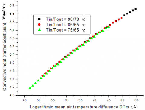
The heat transfer coefficient by convection (αcon) increases with increasing the difference mean logarithmic temperature, which is as shown in Figure 3.
Figure 3. Variation of the heat transfer coefficient by convectionαcon with the difference of logarithmic mean temperature
Figure 4. Variation of the heat transfer coefficient by convectionαcon with the mean temperature difference. Case of a vertical plate flat of Lw = 0.6m [5]
This implies that (αcon) increases with decreasing the temperature of air brought from outside to inside the room for all cases of type of hot water supply system. The heat transfer coefficient by convection (αcon), reaching maximum values when the hot water supply system is: 90 °C/70 °C, then (85 °C/65 °C), and finally (75 °C/65 °C), i.e. (αcon), increases with the increase of the hot water inlet temperature to the radiator (Tin). The results are consistent with the results obtained by Myhren and Holmberg (2009), which are shown in Figure 4.
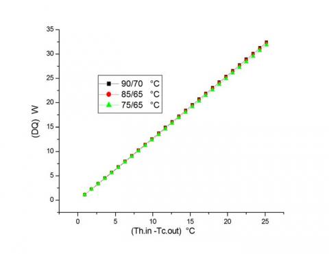
Figure 5 shows that the heat that must be provided to the local is therefore equal to the thermal power of the radiator, it increases simultaneously with the logarithmic mean temperature difference i.e. with decreasing the temperature of supply air coming from the outside, which implies a more consumption energy.
Figure 5. Change in the thermal power of the radiator with the logarithmic mean temperature difference
What makes the system uneconomical. This directly affects the performance of the installation. For analogical reasons between a Heat Pump and a heating system, it is clear that the COP decreases with decreasing temperature of the cold source in all cases. Installation must consume more energy to fight against the quantity of cold caused by the intake of outside air, which increases the costs of installation and makes it very expensive.
The COP increases with decreasing of back temperature to the heat source. Also, by analogy with the heating system, the installation must have a very adequate or optimal COP if we reduced the outlet temperature of the radiator (Tout) as possible. Practically, it means that the radiator has transferred all its heat energy in the room, which increasing the emissive efficiency of the installation. The efficiency increases if we can decrease the temperature at the inlet of the radiator at (Tin=75 °C instead of 85 °C), by setting the outlet temperature at (Tout=65 °C). We also found that if the output temperature of the hot source is reduced, the COP increases. The same result is obtained if we can decrease the temperature at the inlet and at the outlet of the radiator in the same time. Practically, it means that we have economized energy and fuel costs, which makes the system economic.
As shown in Figure 6, the same previous remarks are true, we also note that the coefficient of performance of the HP, decreases with increasing difference temperature between the hot source and the cold source (Th -Tc), it means to have a high COP, we must decrease the difference temperature between the heat source and the cold one (Th -Tc). By combination with the heating system, the installation must consume less energy for combustion and reduce exploitation costs, to make an economic system. Noting also that, work temperatures of existing boilers are generally limited to 75°C, in low and very low temperature since housing is now very well insulated and therefore don’t necessities for high temperatures. From these results, it can be concluded that to improve the performance of a heating system, the heat exchange quantity between the external surfaces of radiator and the ambient air into the room to be heated must be maximally elevated. This may be obtained if we increase the inlet hot water temperature to the radiator (Tin) as a result the heat transfer coefficient by convection (αcon). Practically it means, we will increase the fuel consumption boiler, which makes the installation uneconomical and directly affects the performance of the installation. A radiator outlet temperature (Tout) very low as possible helps the radiator to cede all its calorific heat in the room. Finally, as seen in Figure 6, the best COP in all cases is the last one (Tin/Tout=75°C/40°C) which is decreased the temperature of the outlet of the hot source up to Th=57.5°C, where the COP is equal to 6,8 > 5 (very adequate).
Figure 6. Variation of the coefficient of performance of a heat pump versus the temperature difference between the hot source and the cold source (Th-Tc)
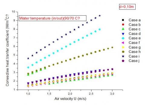
The present study is an attempt to answer the following question; what is the best tube geometry to increase the heat exchange coefficient by convection, in our case, of cross air flow?
As shown in Figure 7, that the heat transfer coefficient by convection (αcon) is higher respectively in case: i, then e, h, c, d, j, a, b, g, and f, (see Table.1). But we must never forget that the circular tube is absolutely the best in the internal fluid flows, knowing that in our case the hot water circulates inside the tubes and plays a major role in the transfer of heat. This is why we have selected geometry “E”, where the tube assumes an elliptical and not circular form, because the pressure inside the elliptical tube is very moderate.
Figure 7. Comparison of convective heat transfer coefficient αcon for different tube geometries in case of a crossflow
In this part, we chose the code Fluent (marketed by Fluent Incorporated version 6.3); this last answer to our computing needs.
6.1 Study objectives
We will study in (2D), a radiator ventilated perpendicularly (cross flow). Consisting of three (03) parallel rows of steel tubes, which are arranged in staggered form. In this study, we want to achieve the following goals:
(1) Realization of a numerical simulation (2D) of air movement between tubes of radiator by detailing predictions profiles of temperature and velocity vectors. And see in which case there may be an optimal heat exchange, reaching maximum temperature in exit air of radiator; by varying the shape of tubes, circular or elliptical, then the distance between axes of the same tubes.
(2) Application of CFD Fluent, (k-e) standard model, with different meshes to study the stability of results in relation to density of the grid.
(3) Judging the aptitude of CFD Fluent, to describe the movement of air between axes of the radiator tubes.
6.2 Geometry
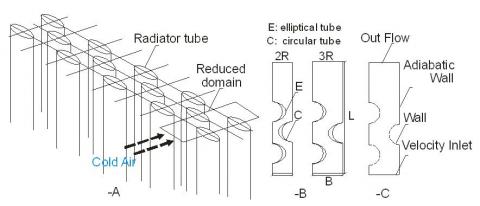
Figure 8. Reduced calculation domain (A), Form geometries (B) and boundary conditions (C)
In terms of material, shape and appearance, the radiator is made up of three (03) parallel rows of steel tubes, immersed in a fluid flow which is air directed perpendicularly to their axis. The tubes are arranged in staggered rows (triangular), remote by an equal step longitudinal and transversal (B =2R) in first time, with a shape of circular then elliptical tube, where the ellipses eccentricity e = 0.7, in second time the longitudinal step (B=3R), with the same transversal step (2R), for the same two forms of tubes. A simplification may be achieved by reducing the total geometry of the domain, to reduce the time of calculation (Figure 8-A).
6.3 Geometry reduction
Symmetry is noticed between the axes of tubes which makes the study of all the radiator reduced in a study of a partial domain as it is shown in Figure 8-B, for raisons to reduce calculation time. The reduced computational domain was numerically studied in two dimensions (2D)with FLUENT and the turbulence model(k-e) standard, in using four types of geometries, characterized by the type of tube of radiator: circular (C) or elliptical(E)and longitudinal (1: means equal at 2R, 2: equal at 3R), or transversal pitch of tubes. Near-wall treatment, a standard wall-function is applied, and two cases are existing: ${{U}^{+}}\,=\,y{{}^{+}}$ (Cellule center p existing in the laminar sub layer), or, ${{U}^{+}}={}^{1}/{}_{k}\ln (E{{y}^{+}})$ (Cellule center p existing in the logarithmic zone), with K = 0, 42 Von Karman constant and E= 9.81.
For each geometry form we varying mesh by edges: B and L, (see Figure 8-B), to check for stability results (see: study of stability of results), where we have: C1-1330x190, C1-1330x95, C1-665x190, C1-444X190, C2-1330x285, C2-1330x143, C2-665x285, E1-1330x190, E1-1330x95, E1-1330x48, E2-1330x285, E2-1330x95, E2-1330x71. The mesh is detailed below.
6.4 Meshes
In the code Fluent, creating geometry and mesh are made under the package «Gambit». They are three types of meshes from the perspective of the cell shape: triangular mesh, quadratic mesh, and mixed (triangle/quads).
Numerical instabilities can be also caused by the triangular shape of the mesh cells [23]. Using a triangular mesh induce a surplus in the number of cells compared with quadrilateral cells, hence the need for more resources and computing time [24-26]. So, we chose quadrilateral cells compared to triangular cells, for spacing between the nodes ranging from 10-4 m, to 4 10-4 m along all borders surrounding the computational domain, Figure 9.
Form A: C1-1330x190, B: E1-1330x190, C: C2-1330x285, D: E2-1330x95
Figure 9. Representation of meshed forms
The number of meshes and nodes used as well as any details are summarized in Table 2.
Table 2. Mesh details
|
Mesh codification |
Quadrilateral cells number |
Number of nodes in the tube surface |
Input or output nodes number |
Interior domain nodes number |
Number of nodes in the rest of domain |
|
C1-1330x190 |
209671 |
894 |
190 |
417660 |
2090 |
|
C1-1330x95 |
185344 |
894 |
95 |
369101 |
2090 |
|
C1-665x190 |
59064 |
447 |
190 |
117192 |
1045 |
|
C1-444X190 |
28940 |
297 |
190 |
57193 |
697 |
|
C2-1330x285 |
336209 |
894 |
285 |
670641 |
2090 |
|
C2-1330x143 |
275548 |
894 |
143 |
549461 |
2090 |
|
C2-665x285 |
97904 |
447 |
285 |
194777 |
1045 |
|
E1-1330x190 |
192933 |
1080 |
190 |
384091 |
2090 |
|
E1-1330x95 |
169842 |
1080 |
95 |
338004 |
2090 |
|
E1-1330x48 |
139123 |
1080 |
48 |
276613 |
2090 |
|
E2-1330x285 |
318765 |
1080 |
285 |
635660 |
2090 |
|
E2-1330x95 |
229481 |
1080 |
95 |
457282 |
2090 |
|
E2-1330x71 |
197696 |
1080 |
71 |
393736 |
2090 |
The study of the effect of mesh on solutions is to compare numerical results using different numbers of nodes; to seek the stability of the results, where we changed the mesh size in the mesh geometry. We noticed that the code Fluent with (k-ε) standard model, with important size mesh is able to provide quickly an estimation of the flow, both about its structure than intensity. In addition, the results obtained by the code Fluent with (k-ε) standard model, with important size mesh or enough fine, are in very good agreement, as well as for the magnitude of temperature as that of velocity.
Form (A)
Form (B)
Form (C)
Form (D)
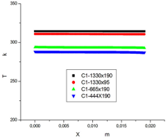
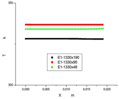
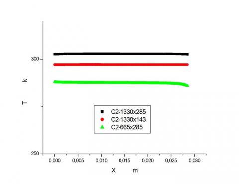
Figure 10. Stability study of Results, temperature profiles in the position y = 0 .133 m, with different meshes for different forms
Figures 10 shows the temperature profiles at the outlet of the computational domain, at position y = 0.133 m, with different meshes (m) for different forms. It was noted that the magnitude of velocity of mean flow is more sensitive to mesh than the magnitude of temperature, which characterizes the energy. With reference to temperature profiles; almost identical solutions are obtained with all the meshes, but the maximum temperature values obtained in all cases must be corresponded at velocity values closer as possible, that's why we chose the following meshes:C1-1330x190 for form A, E1-1330x190 to form B, C2-1330x285 for form C, and E2-1330x95 for form D. (Table 3). Therefore, these meshes were used for the different simulations studied which will be presented below.
Table 3. Results of the stability study - maximum values of velocity (m/s) and temperature (K)
|
Type of geometry |
Mesh Codification (In meters) |
Maximum values of: |
|
|
Velocities m/s |
Temperatures K |
||
|
A |
C1-1330x190 |
3,99797 |
314,406 |
|
C1-1330x95 |
4,09189 |
310,864 |
|
|
C1-665x190 |
2,62889 |
293,572 |
|
|
C1-444x190 |
2,17218 |
288,039 |
|
|
B |
E1-1330x190 |
3,80508 |
328,242 |
|
E1-1330x95 |
7,5438 |
336,837 |
|
|
E1-1330x48 |
6,4038 |
334,401 |
|
|
C |
C2-1330x285 |
3,0230 |
302,878 |
|
C2-1330x143 |
8,50871 |
297,223 |
|
|
C2-665x285 |
2,22688 |
288,024 |
|
|
D |
E2-1330x285 |
3,19391 |
306,877 |
|
E2-1330x95 |
3,52166 |
314,689 |
|
|
E2-1330x71 |
4,67824 |
310,415 |
|
In our work, a study of four (04) full-scale models of a partial portion of a tube radiator is effected, which the flow is assumed to be two-dimensional, with the same boundary conditions, in the entrance domain, a type of condition "velocity inlet" and (k-e) standard model of turbulence with empirical constants: C1ε= 1.44, C2ε= 1.92, Cμ= 0.09 (Launder and Spalding, 1974), turbulent Prandtl number σt=0.85, turbulent Prandtl numbers associated at k and ε respectively σk= 1, and σε= 1.3,are considered; the air velocity at the entrance is Uin=2 m/s, at a constant and uniform temperature Tin =273K. The surface temperature of the external walls of the tubes are constant and uniform and maintained at Tp =353K. Where we have not considered the spatial variations of temperature on the walls, for raisons of simplification. While the other walls of the domain are supposed adiabatic. On exit of the domain, a condition type "outlet" was considered. Types of borders surrounding the numerical domain study are shown in Figure 8-C.
The results obtained in terms of predicting of the flow and temperatures profiles and air velocities using the code FLUENT with (k-e) standard model, are presented in Figures 11.
Figure 11. Velocity contours, temperature contours in the case of form B: E1-1330x190
7.1 Velocity profiles
Unlike into the cavities flows, the air flow velocity inside the domain near the air inlet is high and decreases as one moves away from this last. The velocity is minimum at the entrance of domain and reached maximum values between the tubes (this phenomenon is observed in all the results). We noticed a large number of velocity contours near tubes which means that several phenomena exist around it especially for forms C and D.
7.2 Velocity vectors
Figure 11 shows the type of results obtained by the code Fluent. It presents the appearance of flows obtained using this model to the fourth meshes. The inlet air jet strikes directly and perpendicularly the first tube opposite, since it is observed a parallel flow upstream of the tube, then the jet breaks out in different directions in space to give rise to a disorderly circulation inside the domain and a birth of a turbulent flow, and air does not follow the geometry of the domain, for this reason the flow is off in the middle and not circular. Downstream of the tubes, air does not follow the geometry of the domain too (not a parallel flow) at least for forms C and D.
7.3 Temperature profiles
The large temperature difference between walls tube and air at the entrance reveals several phenomena; that’s why we noticed a significant number of temperature contours near the tubes, which means a large temperature variation, this situation is observed in all results. A red contour corresponds to a high temperature at the output of domain means a great temperature variation in this last, this, is observed for form B. Hence, in other cases (forms A, C and D), temperature variations are relatively low at the outlet, Figure 11. So, the range of variation of the highest temperature is that observed for form B. Globally, we see that all simulations underestimate recirculation.
7.4 Comparison of different forms
The observation of the air temperature profiles along the horizontal line at the exit of the domain at position y=0.133m, to the different forms, the influence of geometry on the air temperature, and it is clear that the geometry of form B (elliptical tube) has the highest temperature along the horizontal line y=0.133 m, which means that the form B, is the best solution to have highest temperatures air at the outlet of the radiator, (Figure 12).
Figure 12. Comparison of temperature at y = 0.133 m, for different forms and different meshes
7.5 Heat exchange and final design
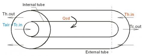
Consider a countercurrent heat exchanger with two concentric tubes (methodic), the air flows are separated by a very good heat-conducting metal wall. The heat losses are assumed to be negligible (the external tube is well insulated and Qh = Qc), and the heat flow is in steady-state. Call mc and Cpc respectively the mass flow and specific heat capacity of the cold air, and mh and Cph, respectively mass flow and the specific heat capacity of hot air.
Figure 13. Representation of different flows in the heat exchanger
Assuming that the thermophysical properties are constant in the heat exchanger, which is as shown in figure 13. The used hot air in the premise pass into the annular passage and cold fresh air passes through the circular central tube. Q is the thermal power exchanged between the two fluids through the surface Ae, it can be calculated either by a global enthalpy balance of fluids:
$Q\,=\,{{m}_{h}}\,C{{p}_{h}}\,\left( {{T}_{h.in}}-{{T}_{h.out}} \right)\,={{m}_{c}}\,C{{p}_{c}}\,\left( {{T}_{c.out}}-{{T}_{c.in}} \right)$ (24)
where, mhCph, and mcCpc are the thermal capacity (with subscript h for the hot air and c to cold air). The fluid that has the smallest heat capacity undergoes the most significant temperature changes (it controls the transfer), so if we assume that the heat capacity of cold air is the lowers, there will be effective on cold fluid side:
${{E}_{c}}=\,\,{\left( {{T}_{c.out}}-{{T}_{c.in}} \right)}/{\left( {{T}_{h.in}}-{{T}_{c.in}} \right)}\;\,,\,\,0\,\le {{E}_{c}}\le 1$ (25)
which of course is dimensionless, and it should be noted that the definition of Ec takes into account three of the four relevant temperatures, we can have then the temperature at the outlet of the heat exchanger, and recalculate (turbulent flow of air or laminar, plate or vertical tube case) the thermal power supposedly transferred by the air discharged to the outside and draw the graph of the difference in thermal power between the last one and the case without heat exchanger.
7.6 The energy saved with the exchanger
The difference of the quantity of energy with and without heat exchanger increases with the increase of the difference of fresh air temperature between the inlet and the outlet of the exchanger i.e. With the significant increase of air temperature from outside which passes through the heat exchanger where it undergoes a preheating by absorbing a quantity of heat from the discharged hot air to outside through the annular passage of the heat exchanger, which is as shown in Figure 14.
Figure 14. Heat flux saved for heating premise, with and without a heat exchanger according to the temperature rise of fresh air
This quantity of energy is the gain of installation (reduction of the energy consumption necessary for heating). What makes the installation economic and performing. This directly affects the performance of the installation.
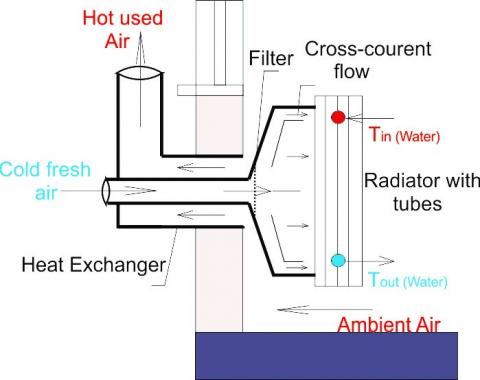
In the new system is placed a heat exchanger at the opening channel in the wall behind the radiator (Figure 15), which will ensure an absorption of quantity of heat from discharged hot air to outside the room, by the new fresh air brought from outside at low temperatures, where it undergoes a pre-heating, the quantity of heat exchanged is the one that makes the difference between the ventilation-radiator and the economic ventilation-radiator, after this preheating, air is flowing directly and perpendicular to elliptical tubes of the radiator for ensure a maximum heat exchange, where it undergoes a heating. To that effect, the radiator cedes all its calorific heat in the room and the very lowest possible temperature at the exit of the radiator, (Tout). It is achieved without increasing the boiler consumption of fuel or electricity, which characterizes this new system.
Figure 15. New economic design of ventilation-radiator system
The quantity of heat gained can be extracted from the water circulating in the radiator which is very important in our new system, and water in the exit of radiator can practically achieve a similar temperature of the ambient air in the room. All this affects directly on performance and makes the heating system economic, and efficient. To ensure a correct flow of fresh air brought from the outside passing within the inner tube of the heat exchanger, and the exhaust air discharged from the room flowing through the annular passage of the heat exchanger which acts as a chimney that flowing air from the interior of the local and rejects to outside, this is ensured by the difference in density between the air inside the room and the air outside this last.
The current study focuses on the efficiency of heat emitters (radiators) in the premises. Heat transfer is optimal when it’s coefficient by convection (αcon) between the air and the walls of the radiator is high, this can be achieved by increasing the inlet temperature of hot water of radiator (Tin) for all cases of type of hot water supply system. Practically it means, we will increase the fuel consumption boiler, which makes the installation uneconomical. In the local, heat that must be provided is therefore equal to the thermal power of the radiator; it increases simultaneously with the logarithmic mean temperature difference i.e. with decreasing the temperature of supply air coming from the outside, which implies a more consumption energy. What makes the system uneconomical. For analogical reasons between a Heat Pump and a heating system, it is clear that the COP decreases with decreasing temperature of the cold source in all cases. Installation must consume more energy to fight against the quantity of cold caused by the intake of outside air, which increases the costs of installation and makes it very expensive. This directly affect sits performance. The efficiency increases if we can decrease the temperature at the inlet of the radiator at (Tin=75 °C instead of 85 °C), by setting the outlet temperature at (Tout=65 °C). We also found that if the output temperature of the hot source is reduced, the COP increases. The same result is obtained and the installation has an optimal coefficient of performance for minimum water temperature at the extremities of the radiator (departing and returning hot water). Practically, it means that we have economized energy and fuel costs, which makes the system economic. Additionally, the installation must have a very adequate or optimal COP if we reduced the outlet temperature of the radiator (Tout) as possible; practically it means that the radiator has transferred all its heat energy in the room. Therefore, to have a high COP, we must decrease the difference temperature between the heat source and the cold source (Th -Tc). The installation must consume less energy for combustion and reduce exploitation costs, to make an economic system. The question now is what is the best tube geometry to increase the heat exchange coefficient by convection, in our case of cross air flow? To answer this question, a study in (2D) is effected numerically with Fluent; on a partial part of domain (Radiator ventilated perpendicularly (cross flow)), in order principally to see in which case there may be an optimal heat exchange, reaching maximum temperatures in exit air of radiator; by varying the shape of tubes, circular or elliptical, then the distance between axes of these same tubes. We noticed a large number of velocity contours near tubes which means that several phenomena exist around it especially for forms C and D. The inlet air jet strikes directly and perpendicularly the first tube opposite, since it is observed a parallel flow upstream of the tube, then the jet breaks out in different directions in space to give rise to a disorderly circulation inside the domain and a birth of a turbulent flow. The large temperature difference between walls tube and air at the entrance reveals several phenomena; that’s why we noticed a significant number of temperature contours near the tubes, which means a large temperature variation, this situation is observed in all results. A red contour corresponds to a high temperature at the output of domain means a great temperature variation in this last, this, is observed for form B. Hence, in other cases (forms A, C and D), temperature variations are relatively low at the outlet. We can say that the geometry of form B (elliptical tube) has the highest temperature along the horizontal line y=0.133 m, which means that the form B, is the best solution to have highest temperatures air at the outlet of the radiator, and the elliptical tubes ensure a very high of heat exchange coefficient by convection in cross flow and staggered arrangement tubes. That results in an important COP of installation, with reduced costs, which making the system economical and exploitation costs reasonable.
Accordingly, we have proposed a new economic system of the ventilation-radiator system, which is based on the increase of exchange heat at the radiator placed in the room to be heated. The ventilation-radiator system, where the radiator is ventilated by the cold air brought from outside is uneconomical. To this end, we proposed another technique, which is placing a heat exchanger at an opening channel in the wall behind the radiator, that recover heat from the exhaust hot air discharged to outside, by the fresh air brought from outside. The difference of quantity of energy with and without heat exchanger increases with the increase of air temperature from outside which passes through the heat exchanger where it undergoes a preheating by absorbing a quantity of heat from the discharged hot air to outside through the annular passage of the heat exchanger. This quantity of energy is the gain of installation (reduction of the energy consumption necessary for heating), and this heat flux recovered advantage our system over other heating systems. What makes the installation economic and performing. This directly affects the performance of the installation.
In perspective, and based on the results obtained, this work can be continued on the following fronts:
• Consideration of heat exchange by radiation between the radiator and the facades of the room.
• A study of the outdoor chimney and heat exchanger, as well as the radiator with more than two rows.
• Studies showing the effects of different parameters such as the geometry of the tubes of the heating body, the inclination of the air flow brought back from the outside.
• Study of exchanges and flows if a metal plate is placed at the outer surface of the radiator towards the ambient of the room to create a vertical flow of air just after the heating and to see the influence on the comfort of the occupants.
• An experimental study of an economical radiator- ventilation system with this new design.
|
A |
Heat exchange surface of radiator (m²). |
|
Ae |
Heat exchange surface of exchanger (m²). |
|
Cp |
Specific heat at constant pressure (J kg-1.K-1). |
|
EC |
Heat capacity of cold air. |
|
G |
Gravitational acceleration (m.s-2). |
|
k |
Turbulent kinetic energy (m2.s-2) |
|
Kt |
Overall heat transfer coefficient (W.m-2.K-1). |
|
L |
Characteristic length of the geometry (m). |
|
Lper |
Perimeter (m). |
|
M |
Flow rate of hot water (kg.s-1). |
|
p |
Pressure (Pa). |
|
Q |
Heat flux (W). |
|
T |
Temperature (K) |
|
U+ |
Dimensionless velocity |
|
V |
Flow velocity (m.s-1) |
|
W |
Mechanical work absorbed by the compressor (J). |
|
y+ |
Dimensionless distance between wall and the first adjacent cellule center (p) |
|
Greek symbols |
|
|
α |
Heat transfer coefficient by convection (W.m-2.K-1). |
|
β |
Expansion coefficient at constant pressure (K-1). |
|
ΔTm |
Logarithmic mean temperature difference (K). |
|
δ |
Thickness (m). |
|
λ |
Thermal conductivity (W.m-1.K-1). |
|
μ |
Dynamic viscosity (kg.m-1.s-1). |
|
ρ |
Density (kg.m-3). |
|
ε |
Rate of turbulent energy dissipation (m2.s) |
|
υ |
Kinematic viscosity (m2.s) |
|
Subscripts |
|
|
a |
Air. |
|
C |
Circular tube. |
|
c |
Cold reservoir or cold source. |
|
cd |
Thermal conduction. |
|
cv |
Thermal convection. |
|
E |
Elliptical tube. |
|
f |
Fluid. |
|
in |
Inlet of the radiator. |
|
h |
Hot reservoir or hot source. |
|
out |
Radiator outlet. |
|
r |
Radiator. |
|
R |
Radius tube. |
|
ray |
Radiation. |
|
s |
Surface. |
|
tot |
Total. |
|
t |
Tube. |
|
w |
Wall. |
|
1 |
Front of the radiator. |
|
2 |
External face of the wall. |
|
Dimensionless number |
|
|
Gr |
Grashoff number. |
|
Nu |
Nusselt number. |
|
Pr |
Prandtl number. |
|
Ra |
Rayleigh number. |
|
Re |
Reynolds number. |
[1] Myhren, J.A., Holmberg, S. (2006). Comfort temperatures and operative temperatures in an office with different heating methods. In: Proceedings of the Healthy Buildings, Indoor Climate, Portugal, pp. 47-52.
[2] Myhren, J.A., Holmberg, S. (2007). Energy savings and thermal comfort with ventilation-radiators - a dynamic heating and ventilation system. Proceedings of Clima 07, Well-Being Indoors, Finland, p. 110.
[3] Myhren, J.A., Holmberg, S. (2007). Summer time cooling with ventilation-radiators. Proceedings of IAQVEC: Indoor Air Quality, Ventilation and Energy Conservation in Buildings, Japan, p. 236.
[4] Myhren, J.A., Holmberg, S. (2008). Flow patterns and thermal comfort in a room with panel, floor and wall heating. Journal of Energy and Buildings, 40(4): 524-536. https://doi.org/10.1016/j.enbuild.2007.04.011
[5] Myhren, J.A., Holmberg, S. (2009). Considerations with ventilation-radiators: Comparisons to traditional two-panel radiators. Energy and Buildings, 41: 92-100. https://doi.org/10.1016/j.enbuild.2008.07.014
[6] Myhren, J.A., Holmberg, S. (2011). Improving the thermal performance of ventilation radiators – The role of internal convection fins. International Journal of Thermal Sciences, 50(2): 115-123. https://doi.org/10.1016/j.ijthermalsci.2010.10.011
[7] Elmualim, A.A., Awbi, H.B., Fullford, D., Wetterstad, L. (2003). Performance evaluation of a wall mounted convector for pre-heating naturally ventilated spaces. Int. Journal of Ventilation, 2(3): 213-222. https://doi.org/10.1080/14733315.2003.11683666
[8] Mundt, E., Gustavsson, M., Leksell, P. (1999). Vent-convectore an experimental study. Proceedings of Indoor Air 99. The 8th International Conference on Indoor Air Quality and Climate, UK, Vol. 5.
[9] Holmberg S. (1984). Methods to increase heat transfer from radiators. (In Swedish), Tekniska Meddelanden, 1984: 3.
[10] Juusela, M.A. (2003). Heating and cooling with focus on increased energy efficiency and improved comfort. Guidebook to IEA ECBCS Annex 37. Low Energy Systems for Heating and Cooling of Buildings, VTT Building and Transport, Espoo.
[11] Airaksienen, M., Jarnstrom, H., Kovanen, K., Viitanen, H., Saarela, K. (2007). Ventilation and building related symptoms. Proceedings of Clima 2007 Well Being Indoors, Finland, p. 110.
[12] Eijdems H.H.E.W., Boerstra A.C. (2000). Low temperature heating systems: Impact on IAQ, thermal comfort and energy consumption. Annex 37 Newsletter 1.
[13] Holmberg, S., Molin, F., Myhren, J.A. (2012). Space heating at low temperature difference between heating unit and ambient air. 9th International Conference on Air Distributions in Room, Coimbra, Portugal, pp. 162-163. https://doi.org/urn:nbn:se:kth:diva-80002
[14] Hasan, A., Kurnitski, J., Jokiranta, K. (2009). A combined low temperature water heating system consisting of radiators and floor heating. Energy and Buildings, 41(5): 470-479. https://doi.org/10.1016/j.enbuild.2008.11.016
[15] Hesaraki, A., Bourdakis, E., Ploskic, A., Holmberg, S. (2015). Experimental study of energy performance in low-temperature hydronic heating systems. Energy and Buildings, 109: 108-114. https://doi.org/10.1016/j.enbuild.2015.09.064
[16] Shati, K.A., Blakey, S.G., Beck, S.B.M. (2011). The effect of surface roughness and emissivity on radiator output. Energy and Buildings, 43(2-3): 400-406. https://doi.org/10.1016/j.enbuild.2010.10.002
[17] Churchill, S.W., Ozoe, H. (1973). Correlations for laminar forced convection with uniform heating inflow over a plate and in developing and fully developed flow in a tube. J. Heat Transfer, 95(1): 78-84. https://doi.org/10.1115/1.3450009
[18] Morgan, V.T. (1975). The overall convective heat transfer from smooth circular cylinders. Advances in Heat Transfer, 11: 199-264. https://doi.org/10.1016/S0065-2717(08)70075-3
[19] Churchill, S.W. (1976). A comprehensive correlation equation for forced convection from a flat plate. AIChE J. 22(2): 264. https://doi.org/10.1002/aic.690220207
[20] Churchill, S.W., Bernstein, M. (1977). A correlating equation for forced convection from gases and liquids to a circular cylinder in cross flow. J. Heat Transfer, 99(2): 300-306. https://doi.org/10.1115/1.3450685
[21] Zukauskas, A. (1987). Convective heat transfer in cross flow. Hand Book of Single-Phase Convective Heat Transfer, Kakaç, S., Shah, R.K., and Win Aung, Eds., Wiley-Interscience, New York.
[22] Kays, W.M., Crawford, M.E. (1993). Convective Heat and Mass Transfer. 3rd ed., McGraw-Hill, New York.
[23] Hadziabdic, M., Hanjalic, K. (2008). Vortical structures and heat transfer in a round impinging jet. J. Fluid Mech. 596: 221-260.
[24] Fluent. (1995). Fluent Incorporated. Fluent User's guide- Version 4.3. Fluent Inc.
[25] Fluent. (2000). Fluent Incorporated. Documentation techniques des logiciels. Fluent.
[26] Fluent. (2006). Fluent, Inc., Fluent 6.3.26 User’s Guide.