OPEN ACCESS
Brushless DC motors have the large applications because of its easiest control system and the highest efficiency. Industrial BLDC motor drives suffers from the ripples in the torque, due to which motor has more noise, vibrations and less efficient. To reduce the ripple, the Space Vector PWM (SVPWM) and Sinusoidal PWM are implemented in BLDC drive. Space Vector PWM control method is implemented and it overcomes the disadvantages in PWM such as losses in switching of the converter, output harmonic content& provides better DC-bus voltages. In this paper BLDC motor with a PI controller fed by a PWM controlling (closed loop controller) converter and also the comparison of SVPWM &SPWM methods presented. The SVPWM makes the drive less ripple in torque& more efficient. The Matlab/Simulink models of SVPWM and SPWM method of the BLDC motor also presented.
BLDC motor, PWM, SVPWM, MATLAB/Simulink.
BLDC motor is supplied from the inverter inverter in 120 degree mode. Due to the electronically Commutation in BLDC motor, the effective speed control is possible and it makes the BLDC is more superior in performance compared to DC brush motors and AC motors. Brushless DC motors have the large applications because of its easiest control system and the highest efficiency. The position of rotor is observed for every 60 degree interval. As the speed of the motor increases, then ripple frequency of torque ripple is also increases, which is undesirable. With ideal trapezoidal back EMF and rectangular currents, motor produces the constant torque. For one cycle of rotor position, there are six intervals each one having 60 degrees. In any one interval, two switches in ON position, i.e. two phases are in conduction. In consecutive interval also two phases are in conduction but only one phase is changing compared to first interval. So for every two consecutive commutation interval the conduction of current is changing from one phase to another phase. Due to the motor inductance, the motor current will take some finite time to rise and fall. During the commutation interval; all the three thyristers are in conduction, so commutation occurs. The conduction of current is changing from one phase to another phase six times. Six torque ripples are producing for every 3600. Torque ripples are existing due to the commutation. Due to the stator and rotor slots interaction, the motor has ripples in the torque. The Industrial BLDC motor drives suffers from the ripples in the torque, due to which motor has more noise, vibrations and less efficient. Modulation techniques will give the variable voltages by making the continuous signal into pulses. This will reduce the magnitude of harmonics and make the output waveform into a pure sinusoidal. The space vector Pulse width modulation makes the motor less torque ripple compared to Sinusoidal pulse width modulation. To reduce the ripple, the Space Vector PWM (SVPWM) and Sinusoidal PWM are implemented in BLDC drive. Space Vector PWM control method is implemented and it overcomes the disadvantages in PWM such as losses in switching of the converter, output harmonic content& provides better DC-bus voltages. In this paper BLDC motor with a PI controller fed by a PWM controlling (closed loop controller) converter and also the comparison of SVPWM &SPWM methods presented. The SVPWM makes the drive less ripple in torque& more efficient. The MATLAB/Simulink models of SVPWM and SPWM method of the BLDC motor also presented. The space vector control method is best suitable for BLDC motor for reducing the torque ripple.
Brushless DC motor (BLDC) has permanent magnet poles on the rotor. BLDC Motors have high efficiency, high power to torque ratio, low noise and better operating performances. BLDC motor is supplied from the converter to control of stator voltage and currents. Due to the electronically Commutation in BLDC motor, the effective speed control is possible and it makes the BLDC is more superior in performance compared to DC brush motors and AC motors. BLDC motors are widely used in hybrid electric vehicles (Yoon, 2005). The BLDC motor does not have brushes and commutator so losses are less and has a long lifetime. The control in supply voltage to the BLDC motors, 3 phase bridge converters (Mondal et al., 2002) are used. Two phases of stator windings are provided supply and the third phase of the stator winding is isolated. The position of the rotor is decided by the two phases which are active. By knowing the rotor position, converter switching devices is turned on. Each switching device is turned on for every 60 degrees. Electronic commutation is happening with this process, So the Back-emf is induced in the stator. BLDC motors have better regulation because of their linear speed and torque characteristics compared to induction motors. So BLDC motors are more suitable for variable frequency drives, electrical vehicle and actuators for industrial robots etc applications.
Torque ripple is the major disadvantage of BLDC motor used in industrial applications. The inverter control contains the harmonics and its cause to have torque ripple (Viswanathan and Jeevananthan, 2015). By using with hysteresis current control, non-ideal Back emf sensing, magnet segmentation, stator and rotor shape designs of Interior Permanent Magnet (Sun-Kwon et al., 2012) etc. methods are used to reduce the torque ripple content for the BLDC motor drive. Modulation techniques will give the variable voltages by making the continuous signal into pulses. This will reduce the magnitude of harmonics and make the output waveform into a pure sinusoidal. The space vector Pulse width modulation makes the motor less torque ripple compared to Sinusoidal pulse width modulation (Bech et al., 2011; Narayanan et al., 2008). The PWM & SVPWM methods are given improved performance for permanent magnet synchronous motors (Ting et al., 2015).
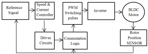
This paper presents the Matlab/simulation of SPWM & SVPWM controlled BLDC motor models. The torque ripple analysis is made on these methods. These methods are reducing the torque ripple and total harmonic distortion in the output. The torque ripple reduction due to space vector Pulse width modulation and Sinusoidal pulse width modulation is presented. The speed control scheme of BLDC motor with PWM technique is shown in fig.1.
Figure 1. Speed control system of BLDC motor with PWM
The most commonly available is BLDC is 3 phase machines with a star (Y) connected winding of displaced by 1200 electrical. BLDCM have a permanent magnet rotor and voltages are induced in the stator winding. The stator winding has self-inductance and mutual inductances. Rate of change of current is opposed by the inductance in the motor. The winding also has a resistance which reduces the applied voltage during current conduction. The angle between stator magnetic field and rotor magnetic field is 900, then because of fields interaction torque is produced. The rotor is rotating then stator windings cut the flux, back emf is produced in the stator windings. The Electrical equivalent of Stator of BLDC motor is shown in fig.2.
Figure 2. Electrical equivalent of Stator of BLDC motor
$\left[ \begin{matrix} {{V}_{a}} \\ {{V}_{b}} \\ V{}_{c} \\\end{matrix} \right]\text{=}\left[ \begin{matrix} R & 0 & 0 \\ 0 & R & 0 \\ 0 & 0 & R \\\end{matrix} \right]\left[ \begin{matrix} {{i}_{a}} \\ {{i}_{b}} \\ {{i}_{c}} \\\end{matrix} \right]\text{+}\left[ \begin{matrix} L-M & 0 & 0 \\ 0 & L-M & 0 \\ 0 & 0 & L-M \\\end{matrix} \right]\frac{d}{dt}\left[ \begin{matrix} {{i}_{a}} \\ {{i}_{b}} \\ {{i}_{c}} \\\end{matrix} \right]\text{+}\left[ \begin{matrix} {{e}_{a}} \\ {{e}_{b}} \\ {{e}_{c}} \\\end{matrix} \right]$ (1)
${{E}_{a}}={{K}_{b}}*f{}_{a}(\theta )*{{\omega }_{m}}$ (2)
${{E}_{b}}={{K}_{b}}*f{}_{b}(\theta -{{120}^{0}})*{{\omega }_{m}}$ (3)
${{E}_{c}}={{K}_{b}}*f{}_{c}(\theta +{{120}^{0}})*{{\omega }_{m}}$ (4)
$F=\left\{ \begin{matrix} 1 & 0\le {{\theta }_{e}}\le \frac{2\pi }{3} & {} & {} \\ 1-\frac{2\pi }{3}({{\theta }_{e}}-\frac{2\pi }{3})\frac{6}{\pi } & \frac{2\pi }{3}\le {{\theta }_{e}}\le \pi & {} & {} \\ -1 & \pi \le {{\theta }_{e}}\le \frac{5\pi }{3} & {} & {} \\ -1+\frac{5\pi }{3}({{\theta }_{e}}-\frac{5\pi }{3})\frac{6}{\pi } & \frac{5\pi }{3}\le {{\theta }_{e}}\le 2\pi & {} & {} \\\end{matrix} \right.$ (5)
To control the stator voltages and frequency inverter control is used, which control the motor speed and the frequency of the supplied voltage. The most used modulation techniques are SPWM and SVPWM, because of its easy design and implementation.
${{T}_{e}}=\frac{4*P*N*{{\varphi }_{m}}*{{I}_{d}}}{\pi *n}$ (6)
${{T}_{e}}=J\frac{d{{\omega }_{m}}}{dt}+{{B}_{m}}*{{\omega }_{m}}+{{T}_{L}}$ (7)
Where TL is the load torque, J is the rotational inertia of the rotor and load, Bm is the viscous damping coefficient.
${{i}_{a}}=\frac{\int{({{V}_{a}}}-{{e}_{a}}-{{i}_{a}}*R)}{(L-M)}dt$ (8)
${{i}_{b}}=\int{\frac{{{V}_{b}}-{{e}_{b}}-{{i}_{b}}*R}{(L-M)}}dt$ (9)
${{i}_{c}}=\int{\frac{{{V}_{c}}-{{e}_{c}}-{{i}_{c}}*R}{(L-M)}}dt$ (10)
${{\omega }_{m}}=\int{\frac{({{T}_{e}}-{{T}_{L}}-{{B}_{m}}*{{\omega }_{m}})}{j}}dt$ (11)
${{\theta }_{e}}\text{=}\frac{P}{2}\text{*}{{\theta }_{m}}\frac{d{{\theta }_{m}}}{dt}={{\omega }_{m}}{{\theta }_{e}}=\frac{P}{2}*\int{{{\omega }_{m}}}dt$ (12)
Where, F= trapezoidal functi on of back emf (per phase)
θe=rotor electrical angle, kb= motor constant, ωm=motor speed, P=number of poles, θe=electrical angle
Va, Vb and Vc are the stator phase voltages. ia,ib and ic are the stator phase currents, L is the self-inductance, M is the mutual inductance, R is the resistance of the stator, Te is electromagnetic torque, Te is load torque and Bm is the damping coefficient.
2.1. PI speed controller
$\omega (t)={{K}_{p}}E(t)+{{K}_{i}}\int{E(t)}dt$ (13)
The most commonly used speed control technique is PI control. It is the conventional controller and commonly used in different control applications for robust and reliable control systems. The difference (error) of reference and actual speed signal is given to the PI speed controller. The Controller generates reference current signals that have the sum of errors and the integral error.
Where,
E(t) = speed signal error,
W(t) = control output signal
Kp = Proportionality gain
Ki = signal integral gain.
The PI speed controller performance mostly depends on the selected best gain values. This will control the speed of BLDC motor and performance.
2.2. SPWM control method
It is very easy and commonly used modulate technique, which is a comparison of three phase sinusoidal signals with the carrier signal at higher frequency, results in the pulses, those can be given to the gate signals to the inverter. Then inverter switches are controlled by comparison of carrier and reference signals. The normalized phase voltage (modulation index) is 0.5. The pulse generation is shown in fig.3.
Figure 3. Pulse generation by SPWM
In the SPWM technique has the triangular frequency (repeating sequence) is the frequency of PWM technique. Converter frequency is controlled by the control voltage frequency. The amplitude is controlled by the maximum value of control voltage. The Modulation Index is given by
$M=\frac{{{V}_{c}}}{{{V}_{triangular}}}$ (14)
Where, Vro1= Fundamental component of supply phase voltage.
If Vc>Vtriangular then Vro=Vd/2 & If Vc<Vtriangular then Vro=-Vd/2.
2.3. SVPWM control method
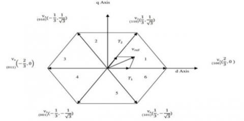
Figure 4. Representation of α, β plane switching combination 100
Figure 5. Vector representation of six states with SVPWM
The principle of SVPWM is converting the three stator voltages into the d-q axis voltages. This makes the easy of calculations and pulse generation than other PWM techniques. Voltage source inverter (VSI) is used to give power supply to the BLDC motor. Space Vector Modulation (SVM) generates the pulses of input supply to the three-level bridge VSI. This method is similar to the DC brushed motor control. Stator frame as divided into d-axis and q-axis. The d-axis currents are controlled the field and q-axis currents controls torque. The three line voltages Vab, Vbc and Vca are displaced by 1200 in space. The representation of the three phase voltages as vectors in two dimensional plane. The sequence of switching has eight possible states. Every switching state is represented depends upon the leg connection of each phase, here ‘1’ indicates that phase leg is connected to the positive plate of the DC link, and ‘0’ indicates that phase leg is connected to the negative plate of the DC link. The ‘100’switching combination represents that the phase-A output terminal Va is connected to the positive DC plate, and phase B and C output terminals Vb and Vc are connected to the negative DC plate. The effective voltage vector generated by this topology is represented as V1. By using this method; the constant DC supply is converted signal into pulses, so the harmonics are reduced. The Representation α, β plane switching combination 100 is shown in fig.4.
Table 1. Specifications of motor
|
Parameter |
Value |
|
Input DC voltage |
150V |
|
Resistance of stator |
0.2 |
|
Inductance of stator |
0.0030 |
|
Load torque |
5Nm |
|
Torque constant |
0.49Nm/A |
|
Moment of inertia |
0.0005 |
|
Number of Poles |
4 |
Similarly the other switching sequences should be represented by the vector diagram like the above. Total switching states with SVPWM are shown in fig.5.
The sector 1 represents the reference voltage. Vref can be represented as
${{V}_{ref}}=\sqrt{\frac{3}{2}}{{V}_{m}}{{e}^{j\theta }}$ (14)
Where, θ=ωt=2πft, $\vec { V } _ { r e f } T _ { s } = V _ { 1 } T _ { 1 } + V _ { 2 } T _ { 2 }$
$T _ { s } = \frac { 1 } { f _ { s } }$, fs=Switching frequency
$\phi = \theta - ( N - 1 ) 60 ^ { 0 }$, Φ=angle within 0 to 60 degrees for each vector.
The switching periods are determined by below equations,
${{T}_{1}}={{T}_{s}}\frac{2}{\sqrt{3}}\frac{{{V}_{ref}}}{{{V}_{1}}}\sin ({{60}^{0}}-\varphi )$ (15)
${{T}_{2}}={{T}_{s}}\frac{2}{\sqrt{3}}\frac{{{V}_{ref}}}{{{V}_{2}}}\sin (\varphi )$ (16)
${{T}_{0}}={{T}_{s}}-({{T}_{1}}+{{T}_{2}})$ (17)
PWM has comparing three input waveforms with the high frequency triangular waveform where as SVPWM three inputs are taken simultaneously into a two dimensional frame (d-q axis) and resultant vector is a single quantity representation. The SVPWM has the advantages of reducing the lower order harmonics and high modulation index. It provides the high Output fundamental voltage, reduced the harmonic content and less THD.SVPWM can be effectively executed in a few microseconds. The motor specifications are given in table1.
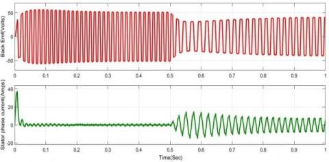
The back emf and stator current simulation results of BLDC motor with the SPWM are shown in fig 8.
Figure 8. Back emf and stator current of a BLDC motor with SPWM
The back emf and stator voltage simulation results of BLDC motor with the SVPWM are shown in fig 9.
Figure 9. Back emf and stator current of a BLDC motor with SPWM
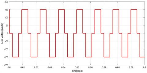
The stator line voltage simulation results of BLDC motor with SPWM are as shown in fig 10.
Figure 10. The stator line voltage of BLDC motor with SPWM
The stator line voltage simulation results of BLDC motor with SVPWM are as shown in fig 11.
Figure 11. The stator line voltage of BLDC motor with SVPWM
From the Fig10 & Fig11 with SVPWM method. The produced stator line voltages have less harmonics compared to the SPWM method. The stator line voltage is approaching to sinusoidal in SVPWM.
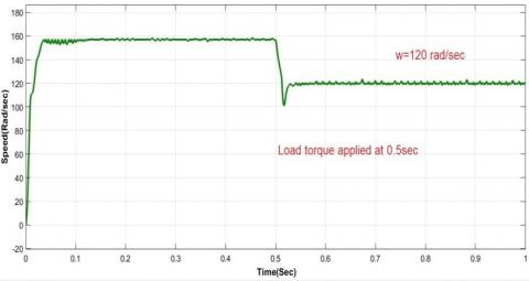
The speed curve of simulation results of BLDC motor with the SPWM is as shown in fig 12.
Figure 12. The speed curve of BLDC motor with the SPWM
From the Fig. 12, the mechanical load of 5 Nm is applied at 0.5 Sec, then the rotor speed falls down and tracking along with the reference speed. In the speed curve, there existing some oscillations in speed. The speed curve of simulation results of BLDC motor with the SVPWM is as shown in fig 13.
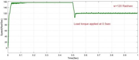
Figure 13. The speed curve of BLDC motor with the SVPWM
From the Fig 14, the mechanical load of 5 Nm is applied at 0.5 sec, the dip in the rotor speed is less in case of SVPWM method compared to SPWM method & speed oscillations are less in SVPWM. The rotor speed is tracking according to the reference speed. The torque wave form of simulation results of BLDC motor with the SPWM is as shown in fig 14.
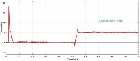
Figure 14. Torque curve of a BLDC motor with SPWM
The torque wave form of simulation results of BLDC motor with the SVPWM is as shown in fig 15.
Figure 15. Torque curve of a BLDC motor with SVPWM
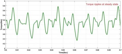
The simulation result of the torque curve at steady state is as shown in fig 16.
Figure 16. Torque curve at steady state with SPWM
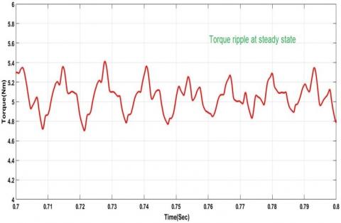
The simulation result of the torque curve at steady state is as shown in Fig 17.
Figure 17. Torque Curve at steady state with SVPWM
Torque Ripple calculation
The ratio of peak to peak value to the average value of torque is defined as the Torque ripple.
${{T}_{ripple}}=\frac{{{T}_{\max }}-{{T}_{\min }}}{{{T}_{avg}}}$ (18)
From the fig17, Torque ripple=(5.7-4.4)/5 = 0.26
% torque ripple=26%
From the fig18, Torque ripple=(5.4-4.7)/5 = 0.14
% torque ripple=14%.
The BLDC motor torque ripple comparison with SPWM and SVPWM conrol methods is given in table2.
Table 2. Torque ripple comparison table
|
S.No |
Method |
% Torque ripple |
|
1. |
Sinusoidal PWM |
26% |
|
2. |
Space vector PWM |
14% |
The performances of BLDC motor are observed by MATLAB/ simulation. With the help of modulation techniques, the torque ripple reduces to some extent. By using the PWM method, the percentage of torque ripple is reduced to 26%. With the proposed SVPWM, the torque ripple still reduced to 14%. The SVPWM is taking less current during speed control and the utilization of DC supply effectively over SPWM method. The speed curve is taking less time to settle and has low oscillations in SVPWM. This result SVPWM is the best suited method to control the converter supply to the BLDC motor.
Bech M. M., Pedersen J. K., Blaabjerg F. (2011). Field-oriented control of an induction motor using random pulse width modulation. IEEE Transactions on Industry Applications, Vol. 37, No. 6, pp. 1777-1785. https://doi.org/10.1109/28.968191
Mondal S. K., Pinto J. O. P., Bose B. K. (2002). A neural-network-based space-vector PWM controller for a three-level voltage-fed inverter induction motor drive. IEEE Transactions on Industry Applications, Vol. 38, No. 3, pp. 660-669. https://doi.org/10.1109/TIA.2002.1003415
Narayanan G., Zhao D, Harish K., Krishnamurthy H. K., Ayyanar R., Ranganathan V. T. (2008). Space vector based hybrid PWM techniques for reduced current ripple. IEEE Transactions on Industrial Electronics, Vol. 55 No. 4, pp. 1614-1627. https://doi.org/10.1109/TIE.2007.907670
Lee S. K., Kang G. H., Jin H., Kim B. W. (2012). Stator and rotor shape designs of interior permanent magnet type brushless DC motor for reducing torque fluctuation. IEEE Transactions on Magnetics, Vol. 48, No. 11, pp. 4662-4665. https://doi.org/10.1109/TMAG.2012.2201455
Ting N. S., Yasa Y., Aksoy I., Sahin Y. (2015). Comparison of SVPWM, SPWM and HCC control techniques in power control of PMSG used in wind TURBINE systems. 2015 Intl Aegean Conference on Electrical Machines & Power Electronics (ACEMP), 2015 Intl Conference on Optimization of Electrical & Electronic Equipment (OPTIM) & 2015 Intl Symposium on Advanced Electromechanical Motion Systems (ELECTROMOTION), pp. 69-74. https://doi.org/10.1109/OPTIM.2015.7426976
Viswanathan V., Jeevananthan S. (2015). Approach for torque ripple reduction for brushless DC motor based on three-level neutral-point-clamped inverter with DC–DC converter. IET Power Electron, Vol. 8, No. 1, pp. 47–55. https://doi.org/10.1049/iet-pel.2013.0471
Yoon T. (2005). Magnetically induced vibration in a permanent-magnet brushless DC motor with symmetric pole-slot configuration. IEEE Transactions on Magnetics, Vol. 41, No. 6, pp. 2173-2179. https://doi.org/10.1109/TMAG.2005.848321