OPEN ACCESS
The main objective of this research is to give as complete as possible analysis of voltage swell and their mitigation in power systems. This objective can be achieved by addressing several tasks in a step by step approach. For every voltage swell magnitude, evolutionary computing methods will be used to determine the parameters of the traditional FACTS like inductor and capacitor values and also these methods will be used to get the best values of PI controller gains connected to the traditional FACTS. So by formation of the variable inductance and capacitance FACTS with variable controller gains for each swell magnitude, we can introduce a new idea namely Advanced Flexible AC Transmission System (AFACTS) for a thorough study of the steady-state and dynamic operation of electrical power systems to improve the power systems quality by mitigating the voltage swell with any magnitude at the affected bus. In order to perform the above-mentioned studies and analysis effectively and accurately on a realistic size power system, an automated comprehensive tool is required for the assessment and visualization of the performance of voltage swell of individual buses and the entire network.
advanced flexible ac transmission system, power quality, swarm intelligence, total harmonic distortion, voltage swell mitigation
The main subject of this paper deals with enhancing the steady-state and dynamics performance of the power grids by using new and powerful idea namely Advanced Flexible AC Transmission Systems (AFACTS) based on Evolutionary Techniques. One of the proposed (AFACTS) namely Advanced Static VAR Compensator (ASVC) was studied and analyzed to mitigate one of the power quality problems known as voltage swells. This article focuses on the operation and the effect of AFACTS devices under several scenarios of voltage swell magnitudes. The idea of new robust ASVC device is that, variable values of inductance and PI gains are used instead of constant values in traditional SVC for each magnitude of voltage swell. Latest optimization techniques are used and compared to Particle Swarm Optimization in order to determine the value of the variable parameters. The performance of the proposed method was tested on IEEE 30 bus system as well as IEEE 57 bus system using PSCAD/EMTDC software linked to MATLAB software. Moreover, the results were compared with traditional SVC, showing that the performance of the proposed ASVC was better than the traditional one. The proposed method also showed to be robust to voltage swell magnitude variations.
In order to demonstrate and understand many operational and electrical power issues, "Power Quality" (PQ) term is identified. One of PQ definitions is a mall operation or failure of customer devices due to any power problem appeared in frequency, voltage, or current distortions (Dugan et al., 1996). So, power quality studies become more important because of its impacts on economic, operation and safety. From sensitive equipments point of view, quality of the voltage is the most important part of power quality. Voltage disturbances mainly include voltage sags, voltage swells, voltage flickers and voltage harmonics. The definition of "Swell" is the rise of rms value of voltage or current, at power frequency, to between 110% and 180% of their nominal value for a period of time between half cycle and one minute. Voltage swell can blow fuses and trip the circuit breakers due to the creation of large unbalance current, also can damage transformers, or even make malfunction or completely shutdown of sensitive equipment in plants. There is variety of techniques to mitigate voltage swells, but one of the most efficient techniques used are those based on the power-electronics.
Flexible AC Transmission Systems (FACTS) forming a modern trend in control engineering linked to power system, using the more recent automatic control theories and technologies and the power electronic circuits and equipments (Acha et al., 2004). They can be divided into two groups, shunt VAR and series VAR compensators. The group of shunt VAR compensators includes "Static VAR Compensators" (SVC) and "Static Synchronous Compensator" (STATCOM) where the group of series VAR compensators includes "Thyristor Controlled Series Capacitors" (TCSC) and "Static Synchronous Series Compensator" (SSSC). Shunt compensators change the impedance at the point of connection, where series compensators alter the parameters of the networks. The performance of the power system can be considerably improved due to the reactive power changed by both of the compensators.
SVC, one of the shunt VAR compensators, is mainly used for voltage swells compensation. The construction of the conventional SVC consists of a Thyristor Controlled Reactor (TCR) in parallel with a fixed capacitor. From a technical perspective, the SVC operates as a shunt connected variable reactance that can produces or draws reactive power to regulate the voltage level at the location of the connection to the system. It is efficiently give voltage regulation support and fast reactive power. Controlling thyristors' firing angles in the SVC supplies it with very fast response (El-Sadek, 2004, Acha et al., 2004). Conventional SVC are the most known compensators in both transmission and distribution systems, employing thyristor as switching elements and being shunt connected to an AC network. These compensators were designed primarily to reduce voltage fluctuations due to arc furnaces and then developed for voltage control purpose.
A considerable amount of technical works has been done on the conventional SVCs concerning control strategy and optimal allocation for set of SVCs. Changing the controller or control strategy of SVCs aims to several results like compensation of harmonics and power factor, damping system oscillations, and voltage control and stability improvements. While the purpose of the optimal allocation of several SVCs is to enhance voltage profile, system stability, optimal power flow and reduce the power losses. Few papers covered the usage of conventional SVC to mitigate voltage sags and swells. Also changing the circuit of the conventional SVC to reduce the harmonic distortion was mentioned in a little amount of papers (Pedro et al., 2017).
A non-linear controller namely "Synergetic controller" used in (Rehan & Choudhry, 2017). The performance of the proposed controller was compared with the SVC with conventional controller based on eigen-value assignment technique. The effectiveness of the proposed controller appeared in damping system oscillations resulted from load variations whereas the conventional linear controller destabilized the system. In (Chaparro & Sosa, 2011), Multi-Objective GA (MOGA) optimization technique was used to optimize the parameters of the SVCs used. Parameters like the reference voltage, the minimum and maximum reactive power, regarded to the limit of reactive compensation capacity of each device were optimized in order to minimize the financial investment for the compensators, the maximum voltage deviation and the total active power loss. In (Taleb et al., 2017), optimal numbering and location of the SVCs devices was obtained by using a line stability index. Also optimal sizing was achieved by using one of heuristic optimization techniques called Cuckoo Search (CS). The proposed techniques enhanced the voltage profile and system stability as well as reducing the overall power losses. In (Panfilov & ElGebaly, 2016), Modified Thyristor Controlled Reactor (MTCR) was proposed to be inserted in SVC instead of traditional TCR. The resulted new SVC showed better performance by reducing harmonics in the developed current hence reducing the cost of required filter. Voltage swell mitigated in (Shahin et al., 2014) by a new model of SVC. In this new model, an inductor was inserted in series with traditional SVC to enhance the performance of the SVC. PSO technique used also to get the best value of the series inductor which minimizes the error in voltage. Multiple values of voltage sags and swells were mitigated using conventional SVC based on power flow solution using Newton-Raphson method in (Caicedo et al., 2017).
In this research work, a new powerful idea namely "Advanced Flexible AC Transmission System" (AFACTS) is proposed to compensate different magnitudes of voltage swells in a user-friendly manner, as no research coverage this problem. The AFACTS device, which used in this article known as "Advanced Static VAR Compensator" (ASVC), was utilized with standard transmission networks to mitigate the voltage swells. Latest optimization techniques like "Whale Optimization Algorithm" (WOA), "Grey Wolf Optimization" (GWO), and Modified Adaptive Acceleration Coefficients PSO (MAACPSO) were used to determine the value of variable inductor of (ASVC) and gains of PI controller under different voltage swell magnitudes. Also some modern optimization techniques like "Particle Swarm Optimization" (PSO), "Adaptive Weighted PSO" (AWPSO), and "Adaptive Accelerated Coefficient PSO" (AACPSO) were used and compared to newer ones. As a result, the best inductor values for (ASVC) and best PI controller gains were obtained for each voltage swell magnitude. Software, Power System Computer Aided Design (PSCAD/EMTDC) with MATLAB, is developed to perform all above described work in a user-friendly manner, to incorporate and improve some of previously developed modules and to offer possibility for future use of monitoring data in swell performance assessment.
The rest of the paper is structured as follows. The traditional and proposed modification of SVC is described in the following section. Then various optimization techniques used are summarized. After that, case studies and simulation results are illustrated. Finally, conclusion of the article is introduced.
In order to make the performance of the electrical networks and devices get better, "Flexible AC Transmission Systems" (FACTS) Technology is interested in active and reactive power management. The idea of FACTS technology includes a lot of tasks concerning with the issues faced by customers and networks jointly, mostly those problems linked to power quality, where FACTS devices can mitigate or improve a lot of power quality issues by appropriate power flow control. Depending on smart control Flexible AC, dependable very fast power electronics, and efficient analytical boxes, FACTS are offered as a most modern idea for the power systems operation. Line impedance, voltage profile and the phase angle at specific buses can be controlled by FACTS. FACTS devices control the power flow through the network and it flows by the control actions of these devices. FACTS are categorized according to the technology, where they are depending on "Thyristor Controlled Reactor" (TCR) or "Synchronous Voltage Source" (SVS), and the connection method in the power system, where they are shunted or series. One of the TCR based shunt devices is SVC. This section focuses on formation, function and steady state characteristics of conventional SVC and proposed ASVC.
2.1. Conventional static VAR compensator (SVC)
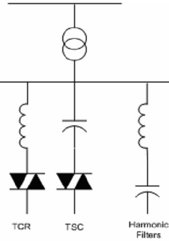
The construction of the conventional SVC consists of Thyristor Controlled Reactor (TCR), Harmonic filter, Thyristor Switched Capacitors (TSC) or fixed capacitor bank, and Transformer as shown in Figure 1 (Luor et al., 1999). Technically, SVC may be considered as a variable reactance that compensates the voltage at the connection point rapidly by absorbing or supplying inductive or capacitive reactive power.
Figure 1. Components of SVC
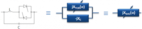
Variation of the firing angle α changes the effective 60 Hz value of the TCR's inductive reactance jXTCR and this, in turn, changes the net value of the reactance jXSVC of the SVC as a whole as shown in Figure 2. The reactive power output from SVC can be varied rapidly and continuously between its capacitive and inductive limits by controlling the reactance of the TCR branch by means of the thyristor firing angle α. The inductive reactance jXTCR of the TCR varies between the value of jXL, and ∞ as the thyristor firing angle α varies from 90o to 180o. The TCR's effective 60 Hz reactance jXTCR is related to the thyristor firing angle α by (1).
$X _ { T C R } ( \alpha ) = \pi X _ { L } / ( 2 ( \pi - \alpha ) + \sin ( 2 \alpha ) )$ (1)
Figure 2. Equivalent reactances of SVC
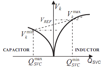
Thus, SVC can be seen as a controllable shunt connected suscepstance BSVC in the network. Figure 3 represents the characteristics curve of the conventional SVC for different operating conditions at steady state condition. The amount of reactive power QSVC injected or consumed by SVC in order to retain the voltage of the bus k connected by SVC can be calculated by (2).
$Q _ { S V C } ( \alpha ) = V _ { k } ^ { 2 } \cdot B _ { S V C } ( \alpha )$ (2)
Where QSVCmin <= QSVC (α) <= QSVCmax, BSVC(α) = 1/XSVC(α), and Vk is the voltage of the bus at which SVC connected.
Figure 3. SVC characteristics curve for different operating condition
2.2. Proposed advanced static VAR compensator (ASVC)
The construction of the ASVC is similar to that of the conventional SVC except that the constant value of TCR's inductive reactance is replaced by variable inductive reactance which varies for each magnitude of voltage swell. Also PI controller in ASVC has variable gains instead of constant gains in traditional SVC PI controller. Variable parameters of ASVC are changed according to the detected magnitude of voltage swell. Detection and monitoring of voltage swells occur in power networks are out of scope of this paper and detailed information can be found in (Wilingthon et al., 2013; Raj & Pragasen, 2007; Meena et al., 2011; Wang et al., 2011).
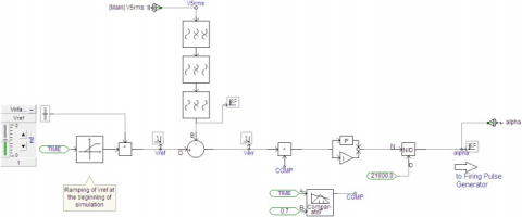
2.2.1. Implementation of ASVC in PSCAD
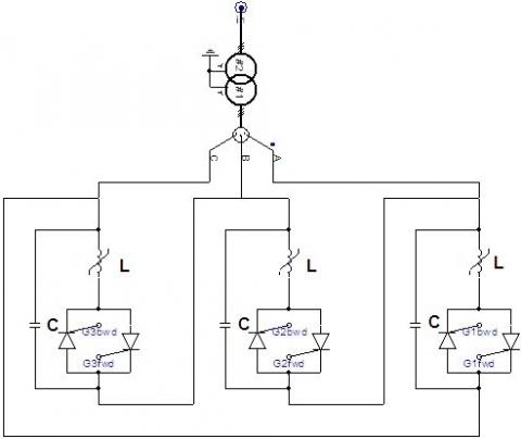
The proposed ASVC model consists of shunt connected TCR branch and Capacitor. Here, Thyristor Controlled Reactor is a variable reactor in series with bidirectional thyristor valve. Three single phase TCRs shunted with capacitors are connected in delta connection in order to be used in a three phase networks. Under not faulty conditions, the harmonic currents of odd-order in zero sequence harmonic components flow in the delta connection and not be allowed to flow to the outside power network. In high voltage applications a step down transformer is required if the TCR needed to be connected as shunt devices because TCR voltages values should be restricted to be 50 kV or below due to technical and economic limits.
Figure 4 shows a delta connected ASVC in three phase system implemented in PSCAD. ASVC regulates voltage by injecting reactive power or absorbing the reactive power at its terminals. As soon as system voltage goes low, it injects reactive power (Capacitive Region). When voltage is high, it absorbs reactive power (Inductive Region). The basic principle of ASVC used in this work is to absorb variable reactive power for each voltage swell magnitude. The flow of current through reactor is controlled by phase angle control of thyristor through adaptive PI controller and the value of the variable reactor in TCR.
Figure 4. Structure of ASVC implemented in PSCAD program
2.2.2. Proposed PI controller of ASVC
Generally, adaptive PI controller with variable gains is used as a control unit in ASVC in order to regulate voltage automatically. Proposed control circuit of ASVC is represented in Figure 5 and it has four stages. They are:
a) Voltage magnitude is measured by three phase RMS voltmeter connected to the bus that is required to control its voltage then filtered by low pass and notch filters.
b) Filtered measured voltage is compared with reference voltage (normally 1.0 p.u.) and error Verr sent to PI controller.
c) Adaptive PI controller chooses the optimal gains according to the voltage swell magnitude then regulates the deviation between the actual voltage and desired voltage in order to reduce the difference to an accepted value. It is done by varying the firing angle α of the thyristors.
d) Firing Pulse Generator generates switching pulses to turn on the thyristors.
Figure 5. PI controller circuit used for ASVC
As mentioned early, variety of optimization techniques based on Evolutionary Computational Techniques (ECT) used in order to optimize the variable reactor and PI controller gains in ASVC. These techniques are implemented in MATLAB program then linked to PSCAD program.
Formerly, evolutionary optimization techniques like genetic algorithm (Keshtkar, 2017) have a wide range of applications. Recently, optimization techniques based on swarm intelligence have been used in many research applications due to their better results. Furthermore, it includes: Particle Swarm Optimization (PSO) (Sundareswaran et al., 2010), Adaptive Weighted Particle PSO (AWPSO) (Vidya et al., 2012), Adaptive Accelerated Coefficients PSO (AACPSO) (Salhi et al., 2013), Modified Adaptive Accelerated Coefficients PSO (MAACPSO) (Bahgaat et al., 2016), Grey Wolf Optimizer (GWO) (Lewis & Mirjalili, 2014), and Whale Optimization Algorithm (WOA) (Lewis & Mirjalili, 2016). All the above optimization techniques were used to get the optimum inductor values and PI gains.
The validation of the proposed ASVC can be shown by testing the model on IEEE 30 bus test system and IEEE 57 bus test system. The model has been built in PSCAD\EMTDC and optimization code of its parameters has been developed in MATLAB. The following constrains have been added to the optimization problem in order to get the best results.
Total Harmonic Distortion factor (THD) ≤ 5.0 % (3)
0.95 ≤ Vk ≤ 1.05 (4)
where Vk is voltage of bus k at which Advanced SVC connected.
It is desirable that the bus voltage deviate from its steady-state value VRef (which is 1p.u.) as little as possible. An error index (E) is proposed here to indicate the transient voltage performance.
$E = \int _ { t _ { 0 } } ^ { T } \left| V _ { r e f } - V _ { k } \right| d t$ (5)
where [t0, T] is the observation interval.
A better controller should result in a smaller error index, so in all optimization techniques, larger fitness will lead to better parameters. Noting that the error index is always positive, fitness function (f) is thus taken as inverse of the error index as in (6), so minimization of the error index (E) is equivalent to maximization of the fitness (f).
f=1/E (6)
4.1. Case one: IEEE 30 bus test system
Technical notes of IEEE 30 bus system is given in (Lee et al., 1985). Bus which has the largest load in the network is assumed as the critical bus which needing a connection of ASVC model to maintain its voltage within acceptable limits during voltage swell. Here, this bus is bus number 5. The values of Qg (to generate a swell) are modified on the bus where the event is due to occur. Table 1 indicates the required capacitive load values that were added to the existing load on bus 5. The purpose of these modifications is to generate the swells. That is, the values specified here do not include the load value that is already on the system.
After applying the various optimization techniques, the best optimization technique leads to the best values of ASVC variable reactor (L), Proportional gain (Kp), and Integral gain (Ki) are illustrated in Table 2 for each voltage swell magnitude.
The reactive power absorbed by ASVC to mitigate voltage swells at bus 5 is presented in Table 3. It is easily seen in Table 2 and Table 3 the increasing of the reactive power absorbed and decreasing in reactor value, as the magnitude of the voltage swell increased.
Table 1. Load connected to bus 5 for swell generation for IEEE 30 bus system
|
Swell Magnitude (p.u.) |
Capacitive Load (MVAR) |
|
1.1 |
220.0 |
|
1.2 |
425.0 |
|
1.3 |
600.0 |
|
1.4 |
740.0 |
|
1.5 |
860.0 |
|
1.6 |
970.0 |
|
1.7 |
1,090.0 |
|
1.8 |
1,170.0 |
Table 2. Optimum values of Variable L, Kp, Ki, and best optimization method for each swell magnitude for IEEE 30 bus system
|
Swell Mag. (p.u.) |
Optimum Values |
Best Optimization Technique |
||
|
L [H] |
Kp |
Ki |
||
|
1.1 |
2.6507E-02 |
1.0000E-04 |
3.7294E+02 |
MAACPSO |
|
1.2 |
1.4784E-02 |
3.2613E+02 |
6.4296E+02 |
MAACPSO |
|
1.3 |
9.6979E-03 |
8.0000E+02 |
3.9904E+02 |
AACPSO |
|
1.4 |
6.3225E-03 |
3.9926E+02 |
5.0225E+02 |
AACPSO |
|
1.5 |
5.6652E-03 |
4.1438E+02 |
8.0000E+02 |
PSO |
|
1.6 |
3.8696E-03 |
8.0000E+02 |
7.8412E+02 |
MAACPSO |
|
1.7 |
2.9193E-03 |
5.4680E+02 |
7.7621E+02 |
AWPSO |
|
1.8 |
2.3909E-03 |
2.4559E+02 |
8.0000E+02 |
AWPSO |
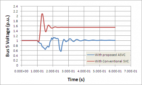
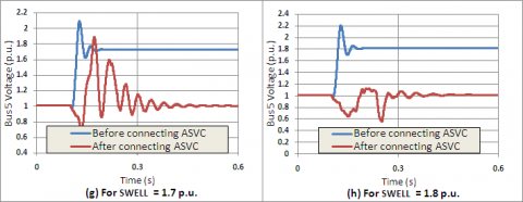
The powerful of the proposed ASVC in compensating the voltage at bus 5 using the optimal variable parameters against the conventional SVC with constant parameters can be observed from Figure 6. Here, the two devices are exposed to voltage swell with magnitude equal 1.8 (p.u.). Conventional SVC compensates the voltage to nearly 1.55 (p.u.) while robust ASVC compensates the voltage to nearly 1.015 (p.u.) after 0.3 (sec).
Table 3. Absorbed reactive power in MVAR by ASVC for each swell magnitude at bus 5 in IEEE 30 bus system
|
Swell Magnitude (p.u.) |
QASVC (MVAR) |
|
1.1 |
268.74 |
|
1.2 |
450.02 |
|
1.3 |
605.61 |
|
1.4 |
773.12 |
|
1.5 |
867.89 |
|
1.6 |
994.36 |
|
1.7 |
1,113.78 |
|
1.8 |
1,189.67 |
Figure 6. Comparison between traditional SVC and ASVC to mitigate 1.8 p.u. swell for IEEE 30 bus system
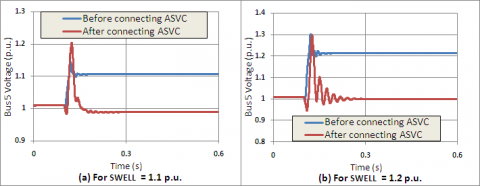
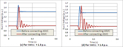
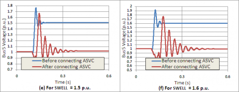
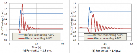
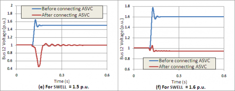
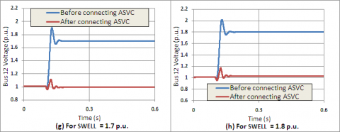
Figure 7 represents the dynamic performance of the proposed advanced SVC while mitigating various magnitudes of voltage swell. As can be seen from most cases in Figure 7, the advanced SVC compensates the bus 5 voltage to almost 1.0 (p.u.) within period of time 0.3 (s) or less.
Figure 7. Comparison between RMS voltage of bus 5 before and after connecting ASVC under voltage swells with magnitudes: (a) 1.1 p.u., (b) 1.2 p.u., (c) 1.3 p.u., (d) 1.4 p.u., (e) 1.5 p.u., (f) 1.6 p.u., (g) 1.7 p.u., and (h) 1.8 p.u.
4.2. Case two: IEEE 57 bus test system
Technical notes of IEEE 57 bus system is given in (Kumar & Premalatha, 2015). Here, the largest load is on the bus number 12. Table 4 indicates the required capacitive load values that were added to the existing load on bus 12 for swell generation.
Table 4. Load connected to bus 12 for swell generation for IEEE 57 bus system
|
Swell Magnitude (p.u.) |
Capacitive Load (MVAR) |
|
1.1 |
300 |
|
1.2 |
580 |
|
1.3 |
840 |
|
1.4 |
1,065 |
|
1.5 |
1,265 |
|
1.6 |
1,445 |
|
1.7 |
1,605 |
|
1.8 |
1,750 |
The optimal values of variable reactor (L), Proportional gain (Kp), and Integral gain (Ki) for ASVC along with the best optimization method are represented in Table 5 for each voltage swell magnitude.
Table 5. Optimum values of Variable L, Kp, Ki, and best optimization method for each swell magnitude for IEEE 57 bus system
|
Swell Mag. (p.u.) |
Optimum Values |
Best Optimization Technique |
||
|
L [H] |
Kp |
Ki |
||
|
1.1 |
2.0603E-02 |
1.0000E-07 |
3.5604E+02 |
AACPSO |
|
1.2 |
9.3262E-03 |
2.1282E+02 |
7.5505E+02 |
MAACPSO |
|
1.3 |
6.2318E-03 |
8.2415E+02 |
9.1218E+02 |
MAACPSO |
|
1.4 |
2.8518E-03 |
7.6660E+02 |
1.0000E+03 |
PSO |
|
1.5 |
1.5807E-03 |
2.8064E+02 |
9.6052E+01 |
WOA |
|
1.6 |
1.0000E-07 |
2.9306E+01 |
1.1224E-07 |
GWO |
|
1.7 |
1.0000E-07 |
4.8338E+02 |
1.0000E-07 |
AACPSO |
|
1.8 |
1.0000E-07 |
1.0000E-07 |
1.0000E+03 |
MAACPSO |
The reactive power absorbed by ASVC to mitigate voltage swells at bus 12 is presented in Table 6. Also Table 5 and Table 6 indicate the inverse relationship between the amount of reactive power absorbed by ASVC and the TCR's reactor during the increase in voltage swell magnitude.
Table 6. Absorbed reactive power in MVAR by ASVC for each swell magnitude at bus 12 in IEEE 57 bus system
|
Swell Magnitude (p.u.) |
QASVC (MVAR) |
|
1.1 |
340.76 |
|
1.2 |
620.64 |
|
1.3 |
829.81 |
|
1.4 |
1,107.55 |
|
1.5 |
1,305.74 |
|
1.6 |
1,514.16 |
|
1.7 |
1,647.81 |
|
1.8 |
1,783.90 |
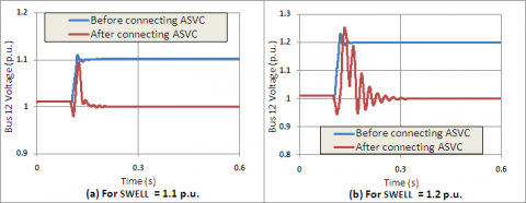
Also in IEEE 57 bus system, the dynamic performance of the traditional SVC is evolved significantly with the proposed modification in compensating the voltage at bus 12. The dynamic performance of the two controllers is shown in Figure 8. Here, the two devices are exposed to voltage swell with magnitude equal 1.8 (p.u.). Conventional SVC compensates the voltage to nearly 1.59 (p.u.) while robust ASVC compensates the voltage to nearly 1.03 (p.u.) during 0.056 (sec).
Figure 8. Comparison between traditional SVC and ASVC to mitigate 1.8 p.u. swell for IEEE 57 bus system
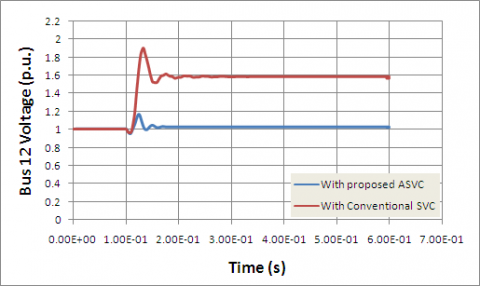
Figure 9. Comparison between RMS voltage of bus 12 before and after connecting ASVC under voltage swells with magnitudes: (a) 1.1 p.u., (b) 1.2 p.u., (c) 1.3 p.u., (d) 1.4 p.u., (e) 1.5 p.u., (f) 1.6 p.u., (g) 1.7 p.u., and (h) 1.8 p.u.
Figure 9 represents the dynamic performance of the proposed advanced SVC while mitigating various magnitudes of voltage swell. As can be seen from most cases in Figure 9, the advanced SVC compensates the bus 12 voltage to almost 1.0 (p.u.) within period of time 0.3 (s) or less.
4.3. Total harmonic distortion
One of the most common indices expressing harmonic effects is the Total Harmonic Distortion factor (THD), which can be calculated for either voltage or current as in (7) (Deilami et al., 2016):
$T H D = [ \sqrt { \sum _ { h = 2 } ^ { h _ { \max } } M _ { h } } ] / M _ { 1 }$ (7)
where Mh is the R.M.S. value of harmonic component h of the quantity M. THD values represented in percentage calculated for bus 5 voltage in IEEE 30 bus system and for bus 12 voltage in IEEE 57 bus system after using ASVC for voltage swell mitigation for different scenarios of voltage swell magnitudes are represented in Table 7.
Table 7. Percentage of THD in bus voltage after using of advanced SVC for IEEE 30 bus and IEEE 57 bus systems under various swell magnitudes
|
Swell Magnitude (p.u.) |
THD for IEEE 30 Bus System (%) |
THD for IEEE 57 Bus System (%) |
|
1.1 |
0.001138 |
0.002236 |
|
1.2 |
0.004323 |
0.006311 |
|
1.3 |
2.868714 |
0.014678 |
|
1.4 |
0.148607 |
0.441399 |
|
1.5 |
0.126844 |
0.29074 |
|
1.6 |
0.358694 |
0.002822 |
|
1.7 |
1.685579 |
0.001128 |
|
1.8 |
4.384365 |
0.001354 |
In this article, control of the electric power system was achieved by introducing the new robust advanced Static VAR Compensator controller. This advanced SVC was designed by making the TCR's reactor and PI controller in conventional SVC to be adapted to various voltage swell scenarios by changing their values. Various optimization methods were applied and compared to determine the optimal parameters of advanced SVC to mitigate any level of swell.
Acha E., Agelidis V. G., Anaya-Lara O., Miller T. J. E. (2004). Power electronic control in electrical systems. Newnes, Great Britain.
Acha E., Fuerte-Esquivel C. R., Ambriz-P´erez H., Camacho C. A. (2004). FACTS modelling and simulation in power networks. England.
Bahgaat N. K., El-Sayed M. I., Moustafa Hassan M. A., Bendary F. (2016). Load frequency control based on evolutionary techniques in electrical power systems. Advances in Chaos Theory and Intelligent Control, Studies in Fuzziness and Soft Computing, Springer. https://doi.org/10.1007/978-3-319-30340-6_36
Caicedo U. J. C., Roa B. J. E., Rivas T. E. (2017). A Newton Raphson based-algorithm for mitigation of sags and swells using SVC and DSTATCOM on the IEEE 30-Bus System. Applied Computer Sciences in Engineering, WEA 2017. Communications Computer and Information Science, Springer. https://doi.org/10.1007/978-3-319-66963-2_18
Chaparro E. R., Sosa M. L. (2011). Coordinated tuning of a set of static var compensators using evolutionary algorithms. IEEE Trondheim Power Tech. https://doi.org/10.1109/PTC.2011.6019284.
Deilami S., Masoum M. A. S., Moghbel M. (2016). Derating active power filters considering network and bus voltage total harmonic distortions. Proceedings of IEEE 16th Inter. Conf. on Environment and Electrical Engineering, Florence, Italy. https://doi.org/10.1109/EEEIC.2016.7555858
Dugan R., McGranaghan M., Beaty H. (1996). Electrical power systems quality. 2nd Ed., New York, United States. ISBN-13: 978-0071386227
El-Sadek M. Z. (2004). Power system voltage stability. Assiut, Egypt.
Keshtkar M. M. (2017). Energy, exergy analysis and optimization by a genetic algorithm of a system based on a solar absorption chiller with a cylindrical PCM and nano-fluid. International Journal of Heat and Technology, Vol. 35, No. 2, pp. 416-420. https://doi.org/10.18280/ijht.350226
Kumar A. R., Premalatha L. (2015). Optimal power flow for a deregulated power system using adaptive real coded biogeography-based optimization. International Journal of Electric Power Energy System. https://doi.org/10.1016/j.ijepes.2015.05.011
Lee K. Y., Park Y. M., Ortiz J. L. (1985). A united approach to optimal real and reactive power dispatch. IEEE Transactions on Power Apparatus and Systems. https://doi.org/10.1109/MPER.1985.5526580
Luor T., Hsu Y., Guo T., Lin J., Huang C. (1999). Application of thyristor-controlled series compensators to enhance oscillatory stability and transmission capability of longitudinal power system. IEEE Transactions on Power System. https://doi.org/10.1109/59.744516
Meena P., Uma Rao K., Ravishankar D. (2011). A simple method for real-time detection of voltage sags and swells in practical loads. European Power Electronics and Drives. https://doi.org/10.1080/09398368.2011.11463801
Mirjalili S., Lewis A. (2014). Grey wolf optimizer. In Advances in Engineering Software. https://doi.org/10.1016/j.advengsoft.2013.12.007
Mirjalili S., Lewis A. (2016). The whale optimization algorithm. In Advances in Engineering Software. https://doi.org/10.1016/j.advengsoft.2016.01.008
Panfilov D. I., ElGebaly A. E. (2016). Modified thyristor controlled reactor for static var compensators. Proceedings of IEEE International Conference on Power and Energy (PECon), Melaka, Malaysia. https://doi.org/10.1109/PECON.2016.7951652
Pedro C. L., Abílio M. V., Leonardo W. de O. (2017). ANN-Based SVC tuning for voltage and harmonics control in microgrids. Brazilian Society for Automatics–SBA, Springer. https://doi.org/10.1007/s40313-016-0281-z
Raj N., Pragasen P. (2007). A new method of voltage sag and swell detection, In IEEE Transactions on Power Delivery. https://doi.org/10.1109/TPWRD.2007.893185
Rehan F., Choudhry M. A. (2017). Design of non-linear static var compensator based on synergetic control theory. Electric Power Systems Research. https://doi.org/10.1016/j.epsr.2017.05.014
Salhi A., Bouktir T., Naimi D. (2013). Economic dispatch resolution using adaptive acceleration coefficients based PSO considering generator constraints. Proceedings of IEEE Int. Conf, CoDIT, Hammamet, Tunisia. https://doi.org/10.1109/CoDIT.2013.6689546
Shahin M., Saied E., Hassan M. A. M., Bendary F. (2014). Voltage swell mitigation using flexible AC transmission systems based on evolutionary computing methods. International Journal of System Dynamics Applications. https://doi.org/10.4018/ijsda.2014070104
Sundareswaran K., Hariharan B., Parasseri F. P., Antony D. S., Subair B. (2010). Optimal placement of Static VAr Compensators (SVC’s) using particle swarm optimization. Proceedings of Int. Conf. on Power, Control and Embedded Systems, Allahabad, India. https://doi.org/10.1109/ICPCES.2010.5698625
Taleb M., Salem A., Ayman A., Azma M. A., Abido M. A. (2017). Advanced technique for optimal allocation of static var compensators in large-scale interconnected networks. Proceedings of 43rd Annual Conference of the IEEE Industrial Electronics Socitey (IECON), Beijing, China. https://doi.org/10.1109/IECON.2017.8216017
Vidya G., Sarathambekai S., Umamaheswari K., Yamunadevi S. P. (2012). Task scheduling using adaptive weighted particle swarm optimization with adaptive weighted sum. In Procedia Engineering, Elsevier, Vol. 38, https://doi.org/10.1016/j.proeng.2012.06.356
Wang J. D., Liu K., Yang G. (2011). Simulation of voltage sag detection method based on DQ transformation. In Electronics and Signal Processing, Springer, pp. 1039-1046. https://doi.org/10.1007/978-3-642-21697-8_132
Wilingthon G. Z., Elton M. C., Juan C. G. M. (2013). Optimal allocation of meters for monitoring voltage sags and swells using the GRASP-VNS optimisation algorithm. Proceedings Of IEEE PES Conference on Innovative Smart Grid Technologies, Sao Paulo, Brazil. https://doi.org/10.1109/ISGT-LA.2013.6554449.