OPEN ACCESS
To protect the environment, world mainly focused on dismissing the exhaustive gases released from the conventional vehicles which are used for transportation, in order to achieve that electric vehicle (EVs)/hybrid electric vehicles (HEVs) are introduced. Primarily EVs are fabricated with a single energy source for its successful operation, those are having some limitations. Hybrid energy storage system (HESS) based EVs are introduced by combining battery with ultracapacitor (UC). Changing of sources present in HESS is the major challenge during real-time implementation according to electric vehicle dynamics. The key objective of this work is to design a control strategy in order to overcome the major challenge associated with HESS powered EV. Four individual math functions are considered and programmed based on the speed of an electric motor, made a new controller named as Math Function Based (MFB) controller. Thereafter different hybrid controllers are formed by combining the designed MFB with ANN as well as PID to perform the switching action of energy sources in HESS.The solar power package is integrated with the circuit to charge the battery during the solar power available time to avoid plug-in charging conditions.Three control switches are connected , which are used to charge the battery as well as supply power to the electric vehicle through the unidirectional converter (UDC) and all these actions are depending upon the state of charge (SOC) of the battery as well as solar power output. Total circuit is implemented with two hybrid controllers and made a comparative analysis based on different factors and tabulated in the conclusion section.
solar power, hybrid electric vehicles (HEVs), bidirectional converter (BDC), unidirectional converter (UDC), battery, ultracapacitor, math Function based (MFB) controller, proportional integral derivative (PID) controller, ANN controller
Generally, all EVs/HEVs batteries are charged from by conventional plugin type only. This type of arrangement all time will not correct the response of the vehicle. The solar panel is integrated with the vehicle itself to charge the battery during the solar power available time and also we can avoid load burden on the local grid. If sunlight not available throughout the day then the vehicle can be charged from a local renewable grid (Sadagopan et al., 2014). A solar power station has proposed for electric vehicle charging, generally many electric vehicles are fed with self-charge mechanism containing with its own PV panel. The designed solar power station can be useful if a vehicle own power is not sufficient to charge the battery (Bhavnani, 1994). Designing of the finest control method to battery/UC based HESS is one of the difficult tasks associated with EVs. This works mainly focusing on developing the supervisory control method which is able to give the optimal power sharing of energy sources. Including both conduction as well as switching losses a DC-DC converter is considered. Numerically a minimized solution is formulated based on the neural network which decides the proper power splitting. Along with the neural network method, a rule-based optimized control technique also implemented and compared both results during vehicle running conditions (Shen et al., 2015). A real-time non-linear control technique is developed and implemented to battery-supercapacitor powered EV. Several non-linearity is considered during changing of the source from on to another according to the driver requirements, with all the considerations predictive control model is obtained and implemented (Wu et al., 2015). Energy management is one of the finest problem present in HESS powered EV/HEVs. In order to obtain the superior energy management of HESS, this includes battery and UC a supervisory energy management strategy is developed. The proposed control technique is purely embedded with different intelligent controllers (Emadi et al., 2008). EVs are extensively used to achieve the green transportation system, for that generally fixed charging as well as mobile charging stations are utilized to charge the energy sources present in the EV. In case of fixed charging stations all charging ports and the other equipment are in stable condition, which means EV itself should reach the particular station to charge the battery/UC. On the other hand, mobile charging stations are available with the movable vehicle, which enhances the flexibility of charging to the EV. In this work proposed the method to charge the battery/UC in a quick way in case of both mobile as well as fixed charging stations (Atmaja, 2015). To obtain the effective energy management of HEV different DC-DC converter topologies are adopted. The supercapacitor (SCAP) bank is integrated into the already existed test bench system. The test bench system mainly containing with two motors and those are separately connected to the alternators to generate the required power to the load. The main intention of this work is to provide peak power with SCAP with a short interval of the time period that may be 20 sec. The original system consisting with main power source only and in this additionally, supper capacitor is connected to enhance the overall performance of the system (Camara et al., 2008).
An effective energy management scheme is designed with a neural network system. The HEV fed with various primary sources like a fuel cell, a battery which is unable to grab the energy during the regenerating period of the vehicle. In order to store energy during regenerating breaking effectively, UC banks are used. In order to store and measure the instantaneous current, vehicle speed and main source voltage values, the digital signal processor is used. Initially, energy management can be done in a conventional way thereafter used a neural network approach to obtain better performance (Moreno et al., 2006). To fulfill the unexpected driver behavior and different load condition, HESS has been designed with various artificial intelligence techniques. Recent preachers mostly concentrating on the optimal usage of fuels which used to drive the electric vehicles mainly on batteries and different algorithms have been proposed to find the optimal way of utilizing the energy sources (Sánchez, 2015; De Castro et al., 2012). During the transforming of traditional vehicles as EVs, several challenges are taking place, in that high power density energy source is the main one and which should be given better results during acceleration and regenerative breaking periods. An FLC based control method is implemented to EV for proper power splitting of energy sources. With the suggested control technique, battery and UC able to give the base as well as peak powers depending upon the vehicle road conditions (Dusmez et al., 2014). For BDC, zero voltage transition (ZVT) circuit is applied in order to create an interface between UC and some other main power sources like a battery which is implemented to HEVs/EVs. The designed auxiliary circuit provides smooth switching of energy sources. The proposed ZVT acts a buck during charging of UC, on the other hand, it will act as a boost during power supply to the load. In this mainly concentrates on the buck operation of BDC, for these different configurations are analysed (Mirzaei et al., 2011). This paper mainly addressed the problems present in control technique which are already existed implemented to EVs and these are powered by HESS. Here the BDC is used to control the current in the battery as well as SCAP actively. Total two control objectives are stated in that first one is used to identify the major source current and load voltage. The second one is used for smooth switching during load changing time (Jung et al., 2014). For multi-source EVs, a real-time energy management system is proposed especially for small urban areas. The energy management system is incorporated the rule-based technique with proper equations will come for proper sharing of energy among multiple sources depending upon the vehicle dynamics. The suggested method gives the optimized energy sharing during all conditions of EV (Trovao et al., 2015). In this, a novel HESS is designed with battery and UC. The traditional HESS has integrated the source through high rating DC-DC converters to the vehicle, whereas in proposed HESS; sources are connected through low rating DC-DC converters to the vehicle. An interface is created between battery and UC in order to meet the peak power requirement of the vehicle. The relative load profile is created to the battery for supplying the power directly to the vehicle even UC voltage value drops to a low value. The battery is not used here to charge directly from the regenerative braking which will reduce the charging and discharging burden (Cao et al., 2012). This work mainly concentrated on designing of a smooth control method of switching for UDC as well as BDC. Here extra core winding is inserted on the existed inductor coil in order to avoid the commutation problem present during working period. Zero voltage switching or hysteresis control is used to perform the transition of converters up to a maximum extent in load. In order to enhance the output power as well as reduce the filtering equipment make sure that main inductor current should be in continues mode (Zhang et al., 2003).
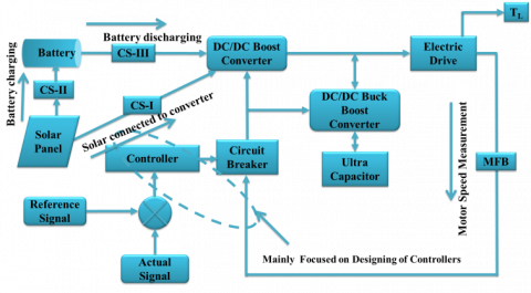
The entire system can be represented by the block diagram in figure 1. The adopted system mainly consisting of controllers, solar panel, battery, UC and different converters. Here the main of the converter is to step up or down the dc voltage depending upon the control signal generated by the particular controller. The battery will act as a major energy source on other hand UC acts as an auxiliary source, which means UC supports the battery during huge power demanding time. UC will take less time to charge in the same releases the same amount of energy within a short period. Solar power is used to charge the battery directly through control switch-2, which will depend upon the SOC of the battery as well as the availability of solar power.
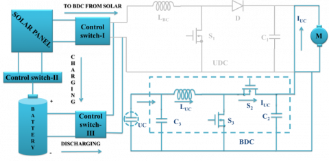
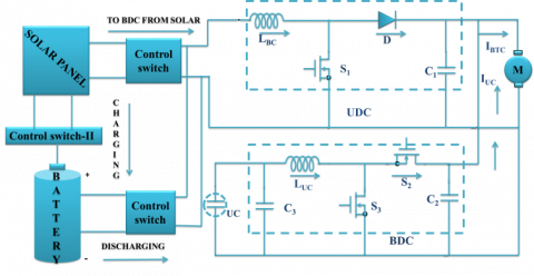
Figure 2 denotes that the main circuit model with DC-DC converters of HESS which consisting of BDC, UDC, battery, UC and solar panel with three switches named as S1, S2, S3 and switch S1 is always in ON condition except for heavy load condition. Here the solar panel has been connected to UDC as well as a battery through control switches I, II and battery have connected to UDC through control switch-III. The battery charging and discharging timings can be decided by the control switches action only. Here a major part of power can be supplied by the battery only on other hand auxiliary power can be supplied with UC that may be starting and transit period of the electric motor.
Figure 1. The block diagram model of HESS with proposed control strategy approach
Figure 2. Main circuit model with DC-DC converters
Each PV cell is capable of generates the voltage of less than one volt which means each Si photovoltaic cell develops the output voltage of around 0.7 V during open circuit time and 0.5 V under working condition. No. of cells are allied in series and parallel to assemble a PV module and a number of modules are allied in series and parallel to produce the required output. Using Si-based photovoltaic modules the PV system converts only 15% of solar energy into electricity. Perfect solar PV cell is demonstrated by a current source and an inverted diode coupled in parallel to it as shown in Figure 3.
Two key parameters are considered from the ideal circuit representation, as short-circuit current (Isc) and open circuit voltage which are often used to illustrate the PV cell. By short-circuiting the terminals of the cell the photon generated current as shown in Figure 3(b), flows out of the cell called as a short circuit current (Isc). Thus, we can say that Icell=Isc as the current Icell is flowing in a single series circuit. As the terminals are short-circuited then the voltage across the circuit is equal to zero i.e Voc=0 and the short-circuit current is the PV cell load current (or the output current which is very maximum as equal to that of the current source or photovoltaic photon generated current i.e. Icell=Isc=Im Similarly, when the terminals are open circuited i.e. no load and nothing is connected as represented in 3 (c), the load current of a PV cell becomes zero. And the load voltage of a PV cell is equal to the maximum applied source voltage or open circuit voltage i.e. (Vm=Voc)
Figure 3. (a) PV cell equivalent circuit, (b) PV cell at short circuit condition (c) PV cell at open circuit condition
The PV cell output current can be found by applying KVL to circuit 3(a)
$\mathrm { I } _ { \mathrm { m } } = \mathrm { I } _ { \mathrm { cell } } - \mathrm { I } _ { \mathrm { d } }$ (1)
The current through diode can be represented with bellow equation
$I _ { d } = I _ { r s c e l l } \left[ e ^ { \left( \frac { Q V } { K T a p } \right) - 1 } \right]$ (2)
By replacing Id in Equation 2, it gives the current-voltage association of the PV cell as shown below
$I _ { m } = I _ { c e l l } - I _ { r s c e l l } \left[ e ^ { \left( \frac { Q V } { K T a p } \right) - 1 } \right]$ (3)
The diode reverse saturation current (Irscell) is calculated by the open circuit condition of PV cell as illustrated in Figure 3(b). From the Equation (3) it is observed that Im=0 and solve for Irscell
$I _ { \text {rscell} } = \frac { I _ { \text {cell} } } { \left[ e ^ { \left( \frac { Q V } { K T a p } \right) - 1 } \right] }$ (4)
The photon generated current is directly relative to the irradiance and temperature, on the other hand, voltage is directly relative to the irradiance and inversely proportional to the temperature. The value of ISCR is provided by the manufacturer datasheet at STC (standard test condition). At STC, the working temperature and irradiance are 250C and 1000 W/m respectively.
In the present work, the standard PV array has been taken and generated the power with different temperatures and irradiance values. Thereafter using DC-DC solar panel voltage has been changed according to the electric vehicle requirement. Here tree control switches have been connected to the solar panel, battery, and UDC. The SOC of the battery and the output voltage of the solar panel decide the control switches action. Finally, electrical vehicle requirement can be fulfilled using solar power based on the availability of sunlight.
The present work mainly concentrated on the design of a new control strategy, which decides the switching time of energy sources in HESS. The proposed method consisting of three controllers (MFB, PID, and ANN), which forms again two hybrid controllers to achieve the main objective of the paper. Among three controllers the MFB plays an important role by controlling the switching pulses generated by remain two controllers PID as well as ANN. Math function U1 only is in enable state during mode-1 operation, in the same way, U1, U2 are in enable state in mode-2 and during mode-3 operation, only U3 is in enable condition, finally, in mode-4 math function U4 only in ON state, remaining all math functions are in disable state. All those disable and enable states of the MFB controller’s leads to produce the controlled switching signals according to the speed of an electric motor. Finally, the MFB plus PID/ANN makes the smooth switching of sources present in HESS. Here U1, U2, U3, and U4 are the generated outputs of MBF controller.
The proposed work can be analyzed in four modes with different loads. Switches action always based on the load condition on the electric motor. All four mode condition with different loads and switches ON and OFF conditions are explained separately in each and every mode of operation.
5.1. Mode-I operation
In this mode, a heavy load is applied to the motor, which initiates the operation of BDC in boost mode. Due to that switch, S3 gets the required pulse signals and other two switches S1, S2 are in disable state. Here the battery gets charged from the solar panel depending on control switches operation. Finally, during this mode of operation, the entire power required by the motor can supply with UC only.
Figure 4. Main circuit model with DC-DC converters during mode-I operation
5.2. Mode-II operation
Slightly more than rated load is related to the mode-2 operation. The battery and UC collectively meet the required power of the electric motor, which means UC is reducing the extra burden on the battery. So switches S1 and S3 are in the active state, another switch S2 is in disable state. In this work, the battery gets charged from the solar panel during sunlight available timings and discharges the same amount of energy to the electric motor during no irradiance and temperature period. Finally, in this mode of operation, the power flows from battery as well as UC to the electric motor.
Figure 5. Main circuit model with DC-DC converters during mode-II operation
5.3. Mode-III operation
During this mode a rated load is applied to the electric motor, due to that switch S1 is in an active state and other switches S2, S3 are in disable state. During rated load condition motor requires average power only, which can be supplied by the battery itself. In this work, the battery gets charged from the solar panel during sunlight available timings and discharges the same amount of energy to the electric motor during no irradiance and temperature period. Finally, in this mode of operation, power flows to the motor from battery only.
Figure 6. Main circuit model with DC-DC converters during mode-III operation
5.4. Mode-IV operation
A light load or no load is applied during mode-4 operation. During this period, motor needs little quantity of power that may be less than average power supply the battery. In this case, the battery can meet the power requirement of the electric motor as well as UC. Switches S1, S2 are in active state and another switch S3 is in disable state. In this work, the battery gets charged from the solar panel during sunlight available timings and discharges the same amount of energy to the electric motor during no irradiance and temperature period. Finally, in this mode of operation, power flows to the motor as well as UC from the battery.
Figure 7. Main circuit model with DC-DC converters during mode-IV operation
The suggested control technique develops the easy path of switching between energy sources present in HESS. Because the designed methodology is purely based on the different road condition of the electric vehicle. In these four modes are considered with different loads and the controlled switching pulses are generated to DC-DC converters by either MFB plus PID/ANN. And how the pulse signals are generating to the particular converter based on the designed control technique can be explained with the bellow flowchart.
Figure 8. Control strategy approach with flow chart representation
(1) With a heavy load and starting of electric motor total power can be supplied by the UC only. The MFB controller generates out signal as 1 for math function U1 and also generates an output signal as 0 for remain math functions U2, U3, U4 corresponding to the speed of an electric motor. In this mode, the motor speed will be£4800 rpm and the BDC will be in operation which is connected at UC end. Finally, the designed MFB combined with other controller initiates to produce the controlled pulse signals to a particular converter.
(2) If slightly more than rated load is applied to an electric motor due to which motor speed is maintained between 4600 rpm to 4800 rpm. The MBF controller produces output signals as 1 for math functions U1, U2 and generates signals as 0 for remain math functions U3, U4 corresponding to the speed of an electric motor. Finally, controlled signals required by the converters can be generated by the designed MFB combined with another controller. UDC and BDC, both are an in-active state, under boost mode. In this mode of operation, UC reduces the burden on the battery by sharing the transient power requirement of the load.
(3) During this mode of operation rated load is applied to the electric motor, which leads to drawing average power by an electric motor. So batteries can delivery total power required by the load. Due to rated load, motor maintains a speed between 4801 rpm to 4930 rpm. The output pulse signal of the designed MFB generates as 1 for math function U3 and generates as 0 for remaining math functions U1, U2, U4 according to the speed of an electric motor. The designed MFB combined with other controller generates a controlled pulse signal to the UDC which will work under boost mode.
(4) During no load or light load condition, the battery is capable to deliver extra power to the load which is used to charge the UC. The output pulse signals of MBF controller generates as 1 for U4 and generates as 0 for U1, U2, and U3 according to the speed of an electric motor. The speed of motor maintained as >4931 rpm. The pulse signals are produced to BDC (buck mode) as well as UDC (boost mode).
7.1. Mode-I operation results (heavy load condition)
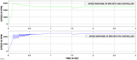
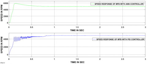
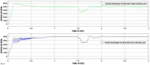
During this mode, a heavy load is applied to the electric motor. MFB with ANN as well as MFB with PID has taken 0.6 sec and 0.9 sec times at starting to reach the steady state. Thereafter at 1.5 sec, a heavy load is applied due to that both the controller's speed responses decreased drastically. MFB with ANN controller has taken 0.8 sec time to reach steady state, whereas MFB with PID doesn’t reach the steady state within a given time.
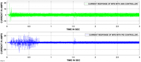
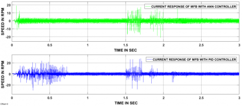
At 1.5 sec a heavy load is applied to the electric motor due to that huge current variations have been observed from above figure 10. MFB with ANN current response reached steady state within 0.8 sec, thereafter no current ripples presented. But MFB with PID current response does not reach the steady state within a stipulated time.
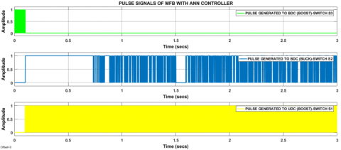
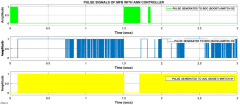
During starting, the motor can stats with UC so controlled pulse signals are produced to BDC (boost), after some time period again controlled signals are produced to UDC as boost and BDC (buck). Due to a heavy load applied at 1.5 sec controlled switching signals are produced to BDC (boost) until response reaches the steady state. After reaching steady state, again controller signals are produced to BDC, working under buck mode and UDC (boost).
Figure 9. Speed responses of two hybrid controllers during mode-I operation
Figure 10. Current responses of two hybrid controllers during mode-I operation
Figure 11. Controlled pulse signals of UDC as well BDC produced by MFB plus ANN controller
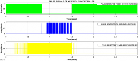
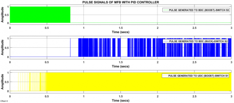
Figure 12. Controlled pulse signals of UDC as well BDC produced by MFB plus PID controller
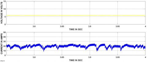
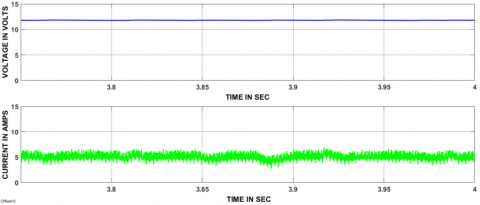
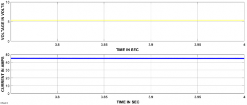
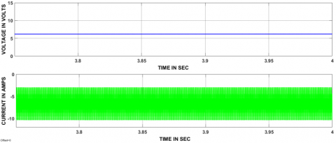
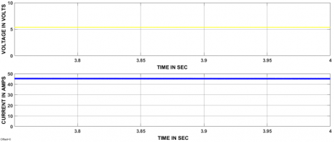
Figure 13. Voltage and current responses of UDC at the input
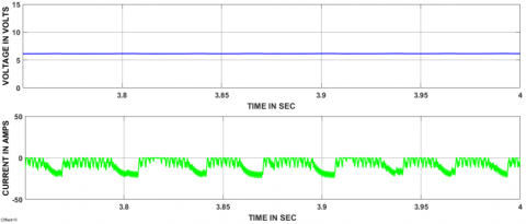
Figure 14. Voltage and current responses of UDC at output
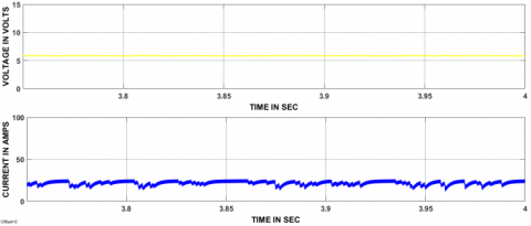
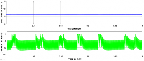
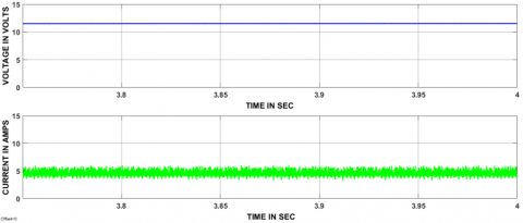
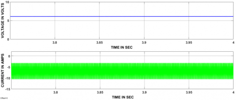
Figure 15. Voltage and current responses of BDC at the input
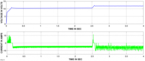
Figure 16. Voltage and current responses of BDC at output
7.2. Mode-II operation results (slightly more than rated load condition)
Figure 17. Speed responses of two hybrid controllers during mode-II operation
Figure 18. Current responses of two hybrid controllers during mode-II operation
Figure 19. Controlled pulse signals of UDC as well BDC produced by MFB plus ANN controller
Figure 20. Controlled pulse signals of UDC as well BDC produced by MFB plus PID logic controller
Figure 21. Voltage and current responses of UDC at the input
Figure 22. Voltage and current responses of UDC at output
Figure 23. Voltage and current responses of BDC at the input
Figure 24. Voltage and current responses of BDC at output
7.3. Mode-II operation results (rated load condition)
Figure 25. Speed responses of two hybrid controllers during mode-III operation
Figure 26. Current responses of two hybrid controllers during mode-III operation
Figure 27. Controlled pulse signals of UDC as well BDC produced by MFB plus ANN controller
Figure 28. Controlled pulse signals of UDC as well BDC produced by MFB plus PID controller
Figure 29. Voltage and current responses of UDC at input
Figure 30. Voltage and current responses of UDC at output
Figure 31. Voltage and current responses of BDC at the input
Figure 32. Voltage and current responses of BDC at the output
7.4. Mode-IV operation results (no-load condition)
Figure 33. Speed responses of two hybrid controllers during mode-IV operation
Figure 34. Current responses of two hybrid controllers during mode-IV operation
Figure 35. Controlled pulse signals of UDC as well BDC produced by MFB plus ANN controller
Figure 36. Controlled pulse signals of UDC as well BDC produced by MFB plus PID controller
Figure 37. Voltage and current responses of UDC at input
Figure 38. Voltage and current responses of UDC at output
Figure 39. Voltage and current responses of BDC at input
Figure 40. Voltage and current responses of BDC at output
7.5. Continuous load condition
Figure 41. Speed responses of two hybrid controllers during a continuous load condition
Figure 42. Current responses of two hybrid controllers during a continuous load condition
Figure 43. Controlled pulse signals of UDC as well BDC produced by MFB plus ANN controller
Figure 44. Controlled pulse signals of UDC as well BDC produced by MFB plus PID controller
Figure 45. Voltage and current responses of UDC at the input
Figure 46. Voltage and current responses of UDC at the output
Figure 47. Voltage and current responses of BDC at the input
Figure 48. Voltage and current responses of BDC at output
Table 1. Comparative analysis of three hybrid controllers in four modes of operation based on a load applied
|
Controller |
Time is taken to reach steady state after applying load on the electric motor |
|||
|
Mode-I (sec) |
Mode-II (sec) |
Mode-III (sec) |
Mode-IV (sec) |
|
|
MFB plus ANN |
0.8 |
0.3 |
0.15 |
No load applied |
|
MFB plus PID |
Not settled |
0.5 |
0.3 |
No load applied |
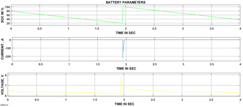
7.6. Battery parameters
Figure 49. The battery parameters during charging and discharging periods
In present work battery minimum SOC has taken as 20%, if battery SOC is bellowed 20% then it should get charged from the solar power directly, in the same way, discharges the same amount of power to the electric vehicle until its SOC reduces to 20%. From the above figure 49, it is clear that during discharging time of the battery current showing positive whereas shown negative value under the charging period.
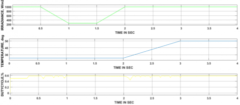
7.7. Solar panel parameters
Figure 50 represents the solar panel input parameters and duty cycle value connected at UDC side. Here solar power can be generated based on the irradiance and temperature availability so, that is the reason why those two parameters have been changed and according to that duty cycle of the converter. The irradiance and temperature values are changed and obtained the different voltage levels corresponding to changed values of irradiance and temperature.
Figure 50. Solar panel parameters and duty cycle of the converter
Table 2. DC-DC converters ON/OFF states based on the mode of operation
|
S.No |
Type of mode |
State of UDC |
State of BDC |
Power flow direction |
|
1 |
Mode-I |
Off |
Boost |
UC supply power to load |
|
2 |
Mode-II |
Boost |
Boost |
Battery and UC together supply power to Load |
|
3 |
Mode-III |
Boost |
Off |
Battery only supply power to load |
|
4 |
Mode-IV |
Boost |
Buck |
The batter can supply power to load as well as UC |
Table 3. MFB controller outputs corresponding to speed
|
.No |
Speed condition associated with mode |
ON State Math Function |
|
1 |
If Speed is ≤4800 rpm |
U1=1&U2=0, U3=0, U4=0 |
|
2 |
If Speed is from 4600 rpm to 4800 rpm |
U1=1,U2=1& U3=0, U4=0, |
|
3 |
If Speed is from 4801 rpm to 4930 rpm |
U3=1 &U1=0, U2=0, U4=0 |
|
4 |
If Speed is >4931 rpm |
U4=1& U1=0, U2=0, U3=0 |
The designed MFB controller is combined with ANN as well as PID controller for enhancing the performance of the eco-friendly vehicles. The suggested control strategy consisting of two controllers, in that PID/ANN one controller and another one is an MFB controller. The designed MFB controller plays a critical role by controlling the pulse signals generated by the ANN or PID controller during switching of energy source according to the speed of an electric motor. The two-hybrid controllers are proposed and implemented to the entire circuit model in all modes and obtained the satisfactory results. Comparative analysis has been made based on the delay, rise, peak, settling times and max peak overshoot and all are tabulated in the conclusion section. From all comparative analysis, MFB with ANN is giving better performance compared to MFB with PID controller.
Table 4. Performance of hybrid controllers based on various parameters
|
Type of Parameter |
MFB plus PI |
MFB plus PID |
MFB plus Fuzzy logic |
|
Delay time (sec) |
0.15 |
0.1 |
0.05 |
|
Rise time (sec) |
2.1 |
1.3 |
0.1 |
|
Peak time (sec) |
2.3 |
1.7 |
0.15 |
|
Settling time (sec) |
2.5 |
1.9 |
0.3 |
|
Maximum peak overshoot (%) |
3 |
2 |
2 |
Table 5. Comparative analysis of controllers during starting and no load condition to reach a steady state
|
Type of Controller |
Controller response time to reach steady with load (sec) |
Controller response time to reach steady state at starting (sec) |
|
MFB plus PI |
0.3 |
2.2 |
|
MFB plus PID |
0.1 |
1.9 |
|
MFB plus Fuzzy Logic |
0.05 |
0.3 |
Atmaja T. D. (2015). Energy storage system using battery and ultracapacitor on mobile charging station for electric vehicle. Energy Procedia, Vol. 68, pp. 429-437. http://dx.doi.org/10.1016/j.egypro.2015.03.274
Bhavnani S. H. (1994). Design and construction of a solar-electric vehicle. Journal of Solar Energy Engineering, Vol. 116, No. 1, pp. 28-34. http://dx.doi.org/10.1115/1.2930061
Camara M. B., Gualous H., Gustin F., Berthon A. (2008). Design and new control of DC/DC converters to share energy between supercapacitors and batteries in hybrid vehicles. IEEE Trans. Vehicular Technology, Vol. 57, No. 5, pp. 2721-2735. http://dx.doi.org/10.1109/TVT.2008.915491
Cao J., Emadi A. (2012). A new battery/ultracapacitor hybrid energy storage system for electric, hybrid, and plug-in hybrid electric vehicles. IEEE Transactions on Power Electronics, Vol. 27, No. 1, pp. 122-132.
De Castro R., Araujo R. E., Trovao J. P. F., Pereirinha P. G., Melo P., Freitas, D. (2012). Robust DC-link control in EVs with multiple energy storage systems. IEEE Transactions on Vehicular Technology, Vol. 61, No. 8, pp. 3553-3565. http://dx.doi.org/10.1109/TVT.2012.2208772
Dusmez S., Khaligh A. (2014). A supervisory power-splitting approach for a new ultracapacitor–battery vehicle deploying two propulsion machines. IEEE Transactions on Industrial Informatics, Vol. 10, No. 3, pp. 1960-1971.
Emadi A., Lee Y. J., Rajashekara K. (2008). Power electronics and motor drives in electric, hybrid electric and plug-in hybrid electric vehicles. IEEE Transactions on industrial Electronics, Vol. 55, No. 6, pp. 2237-2245. http://dx.doi.org/10.1109/TIE.2008.922768
Jung H., Wang H., Hu T. (2014). Control design for robust tracking and smooth transition in power systems with battery/supercapacitor hybrid energy storage devices. Journal of Power Sources, Vol. 26, No. 7, pp. 566-575. http://dx.doi.org/10.1016/j.jpowsour.2014.05.061
Mirzaei A., Jusoh A., Salam Z., Adib E., Farzanehfard H. (2011). A novel soft switching bidirectional coupled inductor buck-boost converter for battery discharging-charging. In Applied Power Electronics Colloquium (IAPEC), 2011 IEEE, pp. 195-199. http://dx.doi.org/10.1109/IAPEC.2011.5779840
Moreno J., Ortúzar M. E., Dixon J. W. (2006). Energy-management system for a hybrid electric vehicle, using ultracapacitors and neural networks. IEEE Transactions on Industrial Electronics, Vol. 53, No. 2, pp. 614-623. http://dx.doi.org/10.1109/TIE.2006.870880
Sadagopan S., Banerji S., Vedula P., Shabin M., Bharatiraja C. (2014). A solar power system for electric vehicles with maximum power point tracking for novel energy sharing. In India Educators' Conference (TIIEC), 2014 Texas Instruments, pp. 124-130. http://dx.doi.org/10.1109/TIIEC.2014.029
Sánchez Ramos L., Blanco Viejo C. J., Álvarez Antón J. C., García García V. G., González Vega M., Viera Pérez J. C. (2015). A variable effective capacity model for LiFePO4 traction batteries using computational intelligence techniques. IEEE Transactions on Industrial Electronics, Vol. 62, No. 1, pp. 1960-1971. http://dx.doi.org/10.1109/TIE.2014.2327552
Shen J., Khaligh A. (2015). A supervisory energy management control strategy in a battery/ultracapacitor hybrid energy storage system. IEEE Transactions on Transportation Electrification, Vol. 1, No. 3, pp. 223-31. http://dx.doi.org/10.1109/TTE.2015.2464690
Trovao J. P. F., Santos V. D., Antunes C. H., Pereirinha P. G., Jorge H. M. (2015). A real-time energy management architecture for multisource electric vehicles. IEEE Trans. Industrial Electronics, Vol. 62, No. 5, pp. 3223-3233. http://dx.doi.org/10.1109/TIE.2014.2376883
Wu D., Todd R., Forsyth A. J. (2015). Adaptive rate-limit control for energy storage systems. IEEE Transactions on Industrial Electronics, Vol. 62, No. 7, pp. 4231-40. http://dx.doi.org/10.1109/TIE.2014.2385043
Zhang Y., Sen P. C. (2003). A new soft-switching technique for buck, boost, and buck-boost converters. IEEE Transactions on Industry Applications, Vol. 39, No. 6, pp. 1775-1782.