OPEN ACCESS
This paper aims to develop a new control architecture of wheeled mobile robot that supports the start-up and stop of robot driven by dual hub motors, the forward and reverse rotation of hub motors, and the coordinated control of two wheels in motion. Inspired by three-phase power supply, Hall signal detection, and square wave driving mode, the hub motor control system was made up of a power circuit, a three-phase full bridge inverter circuit, a Hall signal detection circuit, a peripheral circuit of STM32 single chip microcomputer, communication circuits, a current detection circuit, an over-current detection circuit, a key input circuit, and a printed circuit board (PCB). With the aid of Keil software, the following programs were developed for the hub motor control system, namely, the keypad detection program, the organic light-emitting diode (OLED) module driver, speed detection program, proportional–integral–derivative (PID) support program, motor startup program, motor commutation program, motor speed PID control program and motor stop program. This research successfully optimizes the vehicle control architecture and simplifies the control logic, allowing the vehicle controller to send simple instructions and achieve the basic motion control of the robot body.
Wheeled mobile robot, Brushless direct current (DC) motor, Proportional–integral–derivative (PID) control, Digital control system, Three-phase full bridge inverter
With the booming development of the field of robotics, dual motor drive mode is widely adopted in the chassis of small wheeled mobile robots, such as the greenhouse operating robot, cleaning robot, a security inspection robot, guiding robot, and so on (Chiu et al., 2012; Su et al., 2010; Zhao et al., 2011). At present, most wheeled mobile robot motors adopt the hub motor based on Brushless DC Motor (BLDC). The robot driven independently by the hub motor eliminates the mechanical components necessary for traditional steering mechanism such as clutch, differential, reducer and transmission, reduces the quality of the robot, reduces many unnecessary mechanical transmission losses, and increases the flexible driving characteristics of the robot. (Lu et al., 2012; Zhang et al., 2014; Cochrane et al., 2012).
Wheeled mobile robot is usually through the vehicle controller, analog potential signal and brake signal, communication with the motor driver, the motor control. This control mode can only realize simple start-up and stop motion control of the motor, and cannot meet the control requirements such as forward and reverse rotation and two-wheel coordination control. Many scholars and experts at home and abroad, have carried out related researches on the control system based on 51 single chip microcomputer (Han & Zhou, 2014), trajectory tracking control system, four-wheel independent drive coordinated control system, the efficiency of the motor based on fuzzy logic control (Xu & Shao, 2009), motor speed regulation based on internal model control (Li & Gu, 2012) and other aspects of wheeled mobile robots. For the deficiency of the above control mode, this paper designed the control circuit, control program and control strategy for the wheel motor control system of the wheeled mobile robot, so as to achieve the simple command sent by the whole vehicle controller, which can quickly and accurately control the basic motion of the robot body.
The main research contents include mechanical structure of the wheeled mobile robot, drive circuit design, control circuit design, control program design, design of motor speed acquisition program, conclusion.
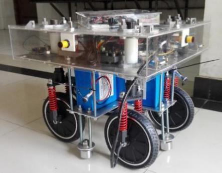
The chassis of the wheeled mobile robot is as shown in Figure 1. The control circuit and the drive circuit of the hub motor are designed separately in order to ensure the smooth operation of the robot chassis. The robot body adopts a four wheel structure, of which, when the robot moves forward, the two front wheels are the driving wheels, while the two rear wheels become the driving wheels when it moves backwards.
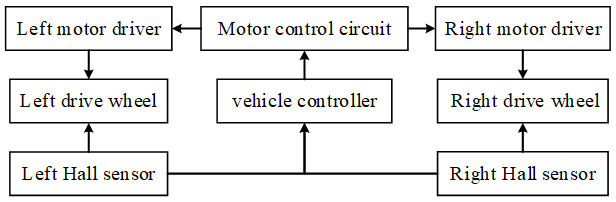
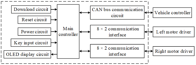
Regardless whether it moves forward or backwards, the control architecture of the wheeled mobile robot over the hub motor can be illustrated as the control architecture shown in Figure 2. The control circuit receives the instruction sent by the vehicle controller, and then sends the driving instruction to the motor drive circuit, which drives the hub motor to run. The rotor position detection is completed with the Hall element thus every position of the motor rotor will correspond to one unique Hall code. By reading its value, the position of the motor rotor at any time can be known, then afterwards, the specific commutation signal can be sent.
The common methods for hub motor speed include the M method, the T method and the M/T method. In this paper, the hub motor speed is measured by a modified T method, that is, on the basis of the T method, the speed is calculated by collecting the time interval every six Hall signals, thus the measurement result of the T method at a high speed is optimized, and at the same time, the resource consumption of the single chip microcomputer is reduced.
Figure 1. The chassis of the wheeled mobile robot
Figure 2. The overall architecture of control system
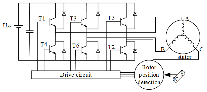
As is shown by the hub motor commutation control principle in Figure 3 (Lu et al., 2012), six MOSFETs form a three phase full bridge inverter circuit on the drive end, and a single chip microcomputer controls T1-T6's on-off, then the conduction state between the motor drive voltage input terminals A, B and C phases can be brought in control. When AB-AC-BC-BA-CA-CB is conducted in turn, the motor rotor completes one commutation cycle. When the motor reverses, it only needs to output the commutation order opposite to that of the forward rotation. In this way, the drive of the brushless motor is converted into a real-time detection of the motor angle, and the corresponding drive signal is output under the given motor angle.
Figure 3. Principle of motor drive circuit
The main controller chip of the motor control circuit is STM32F103RC, which is no longer described.
The speed regulation of Hub motor and Brushless DC Motor is basically the same, which usually achieved by regulating voltage. The commonly used methods for it include DC/DC conversion (Alexandridis & Konstantopoulos, 2014), thyristor phase shift voltage regulation (Stel’makov et al., 2014), and voltage regulation of PWM duty ratio modulation, among which the first one will increase the cost of the circuit, and the second one has complex flows. Thus the voltage regulation of PWM duty ratio modulation is adopted in this paper for speed regulation.
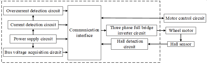
The motor drive circuit includes power supply circuit, three phase full bridge inverter circuit, current detection circuit, overcurrent detection circuit, bus voltage acquisition circuit, Hall signal detection circuit, etc. The overall architecture of the motor drive circuit is as shown in Figure 4.
Figure 4. Architecture of the motor drive circuit
3.1. Design of gate drive circuit
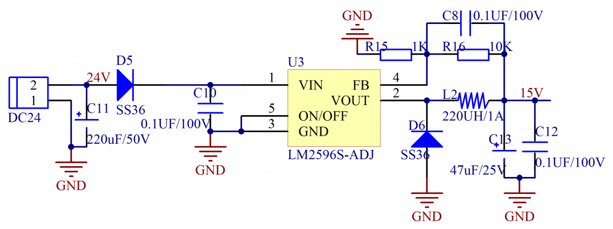
MOSFET is selected as the switching device of the three-phase full bridge inverter circuit. It is necessary to exert the 15V conduction voltage to the gate and connect the 24V charging power supply to the system from outside in order to conduct the MOSFET. As shown by the design of the motor drive power circuit in Figure 5, the output voltage is regulated by the resistance R15, R16, and R15=1K Omega, R16=10K Omega. iode D5 is used to prevent power supply reversal connection, and the output end uses 220uH inductor L2, capacitor C12 and C13 for stabilizing filter.
Figure 5. Design of the motor drive power circuit
3.2. Design of three phase full bridge inverter circuit
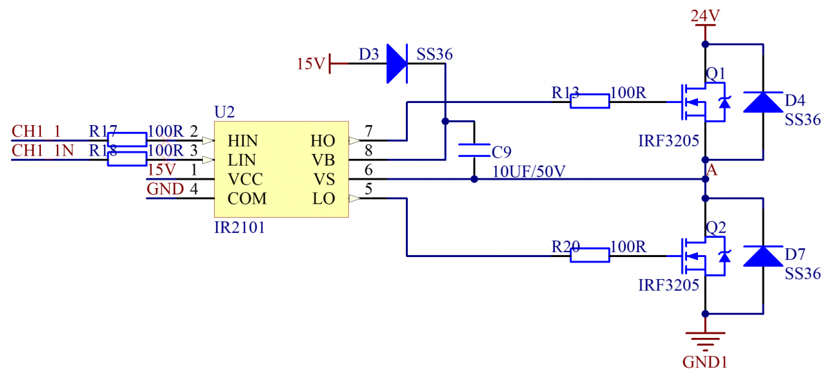
The brushless hub motor is an AC motor, but the system uses 24V DC power supply, so it is necessary to convert the DC power into alternating current, and three phase full bridge inverter circuit is selected as inverter circuit. The principle of A phase inverter circuit is as shown in Figure 6. Through the coordination of three inverter circuits, the DC to AC inverse transformation can be realized. The Bootstrap capacitor C9 selects 10uF ceramic capacitor, diode D4 and D7 help the MOS freewheeling to prevent the commutation current shock to burn down the switching device. N type MOSFET IR3205 is selected as both high and low side switch devices.
Figure 6. A phase inverter circuit
3.3. Design of Hall signal detection circuit
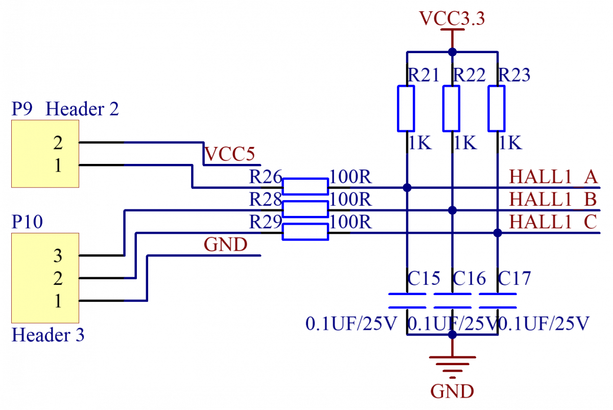
It is necessary to detecte the rotor position of the hub motor while the motor is running, in order to output the correct commutation signal. Three Hall sensors inside the motor are used for doing this (Zou et al., 2002). The output level signal is sent to the MCU interface to complete the signal detection. Hall signal detection circuit is as shown in Figure 7. P9 and P10 are the wire holders, which are connected to the Hall module of the motor to function as the input port for the Hall module power supply and the Hall signal. HALL_A, HALL_B, HALL_C are connected to the 4 Hall capture pins of the single chip timer.
Figure 7. Hall signal detection circuit
3.4. PCB design for motor driver
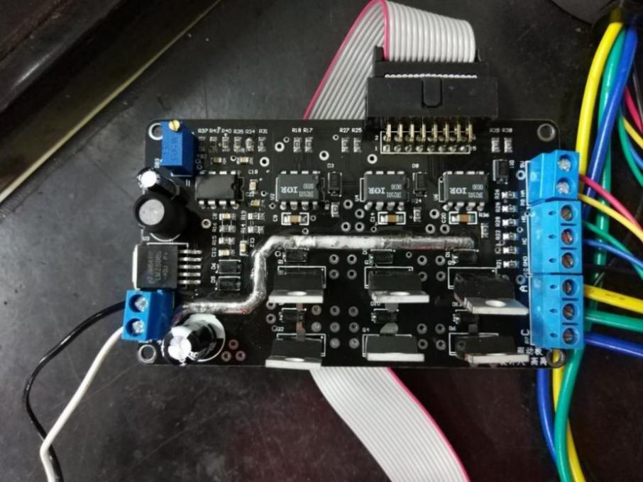
Figure 8. The welded motor drive
The rated power and the drive voltage of the hub motor is 240W and 24V respectively, so the motor driver should have the driving capability of 10A. Therefore, the design of PCB shall focus on the realization of the heat dissipation and driving capability of the motor. In order to meet the requirements, all the power lines are routed with a single layer and no via holes are punched while wiring for the driver. The external diameter of the non power supply line is 50mil, the internal diameter is 28mil, the line width of the control line is 10mil, and the line width of the power line is 118mil. After the wiring is completed, the power line is copied to the group welding layer, exposing the power line, so that the heat dissipation capacity is improved. The resistance and capacitance package all choose 0805 surface mounting and package to improve the overall heat dissipation of PCB. After PCB proofing is completed, a thick layer of tin is applied on the exposed power lie to improve the power flow through the power lie so as to improve the heat dissipation capacity. The PCB board is designed according to the above rules. The circuit board after welding and tin plating is as shown in Figure 8.
Figure 9. Control circuit architecture
The design contents of control circuit include control power supply circuit, minimum system of single chip microcomputer, CAN communication interface circuit, key circuit, OLED circuit, communication interface circuit, brake signal acquisition circuit, etc. As shown in Figure 9, in the overall frame of the control circuit, STM32F103RC is used as the main controller chip model (Zhang & Kang, 2013).
4.1. Design of CAN bus communication circuit
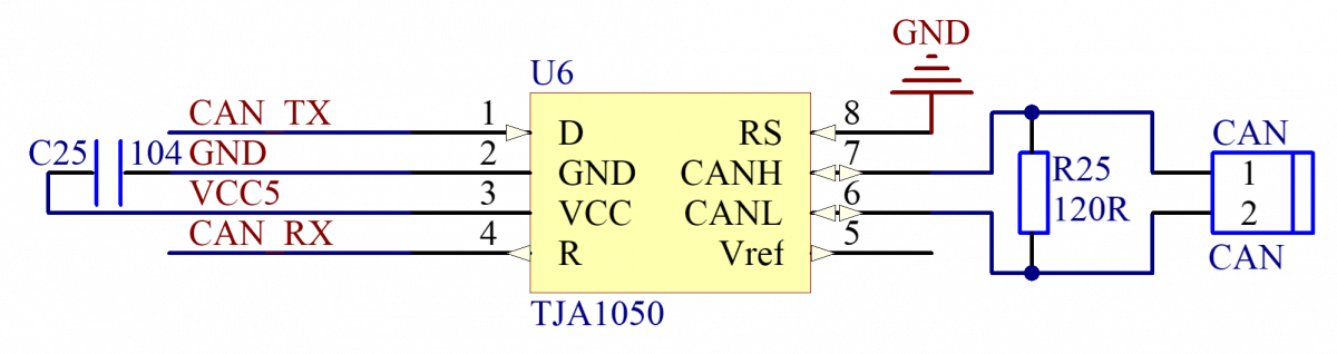
The built-in CAN bus controller interface of the STM32F103RC, shares the same group of IO ports with the USB interface. The IO port is connected with the TJA1050 transceiver chip, and with the external CAN bus through the CAN terminal. The bus communication circuit is as shown in Figure 10. The value of the terminal resistance R25 between CANH and CANL is 120 Omega.
Figure 10. CAN bus communication circuit
4.2. Design of control panel and driver board communication circuit
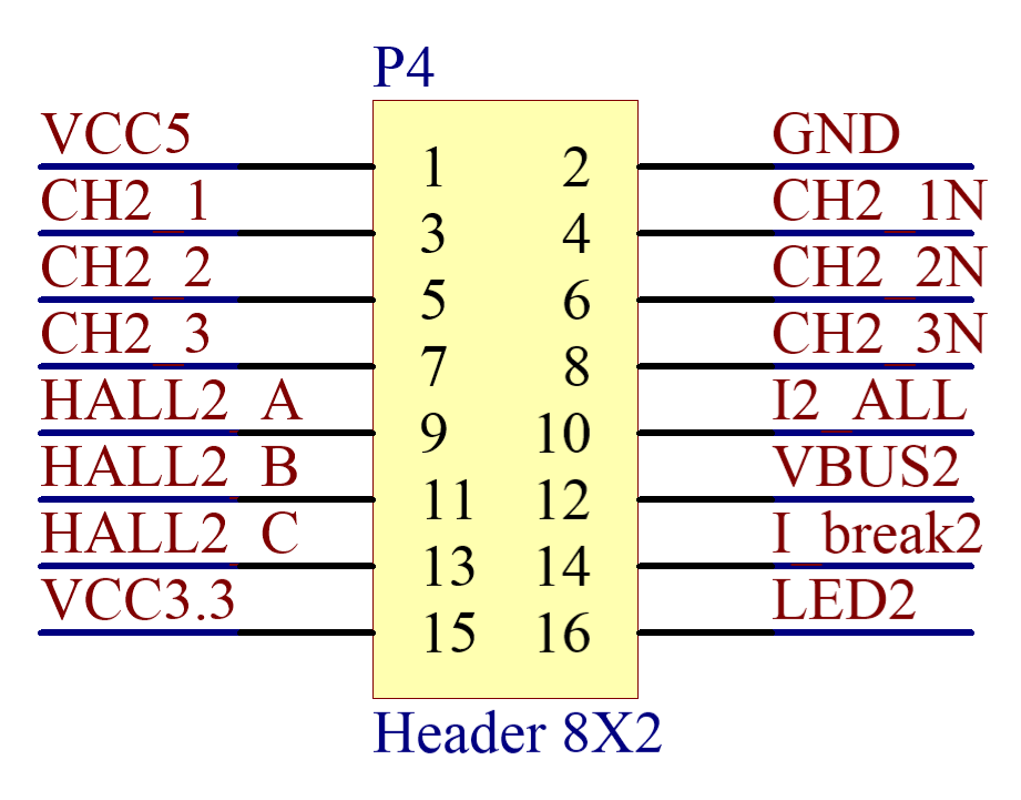
The control panel and the drive board communicate through the 2*8 line, as shown by the communication circuit in Figure 11. Communication signals include: 6 types of MOSFET gate drive signals, CH2_1, CH2_2, CH2_3, CH2_1N, CH2_2N, and CH2_3N, that control the conduction and on-off of MOSFET; 3 types of Hall signals for motor speed detection, HALL2_A, HALL2_B, and HALL2_C, the control panel sends the corresponding commutation signals by determining the status of the motor Hall; the bus voltage signal VBUS2, the control panel determines the battery status by detecting the bus voltage; overcurrent signal I_break2, when the overcurrent signal is detected, the control panel shuts off the commutation output, and the power supply of the driving board motor is cut off; The LED2 display signal is used to display the system's running state.
Figure 11. Communication circuit
4.3 Design of the main controller PCB
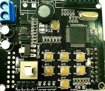
The control panel only completes the realization of the motor control algorithm, and the running current is very small, so the PCB selects the boards with two layers. The basic circuit parameters of the PCB layout are as shown in Table 1. The circuit entity after welding is as shown in Figure 12.
Table 1. The basic circuit parameters controlling the PCB layout
|
Walk line width |
A hole size |
Copper thick |
Resistance to encapsulation |
Capacitor encapsulation |
LED packaging |
|
7mil |
Outer diameter is 25mil and inner diameter is 12mil. |
1OZ |
0603 |
0603 |
0805 |
Figure 12. Control panel after welding
The real-time system of μC/OS-III is run on STM32F103RC single chip microcomputer, and the software of Keil is used to develop the motor control program (Lu et al., 2012). The main tasks of this project include motor commutation task, motor start task, key scanning task, OLED display task, PID calculation task and speed calculation task.
After setting up the development environment, all the peripheral resources are initialized in the main function, which include disabling the JTAG interface, configuring interrupt priority groups, initializing the delay function, and initializing the OLED communication interface. The advanced timer 1 and the timer 8 are initialized to realize the PWM output by setting the reload register and the PWM comparison register of the timer; the input capture interface of timer 3 and timer 4 is initialized for edge capture; the ADC control register is set up and the ADC conversion interface is initialized; the rotational speed closed loop PID variable is created and the PID control parameters is initialized; the real-time system of μC/OS is initialized, and the program is finally stopped at while (1), then the subsequent task will completed by the μC/OS system.
In program design, a start task, start_task, is created to complete the creation of all user tasks, software timers, and signal quantities. The start task hangs only after one run to avoid objects being repeatedly created.
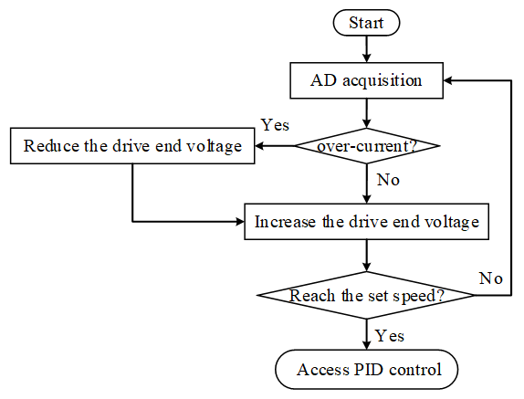
The rated current of the hub motor is 10A. thus it is necessary to design a suitable starting strategy to avoid damage of current shock to the motor when the motor is directly started. As shown in Figure 13, with non-polar start-up mode, the motor start-up flow gradually increases the voltage at the drive end and simulates the sliding rheostat function of the traditional non-polar start-up through the program.
Figure 13. Motor start-up flow
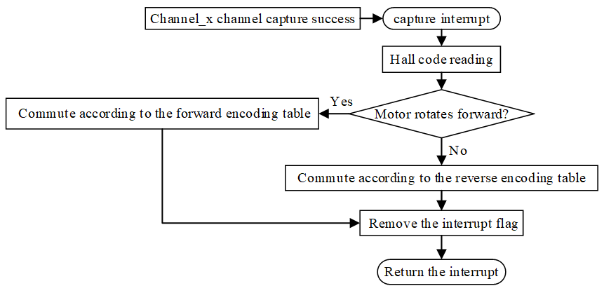
The motor commutation control flow is as shown in Figure 14. There are three Hall sensors inside the motor, which detect the rotor angle in real time. Each Hall element outputs two states, 0 and 1. The three Hall elements are numbered. After the Hall element is energized, each of the motor's rotation angle corresponds to a unique Hall code.
Figure 14. Motor commutation control flow
Hub motor speed is controlled by using incremental PID (Shi & Yu, 2013) (Carlucho et al., 2017). Considering program readability and development convenience, the structure variable PID is defined.
The member variables that this structure contains and their meanings are as follows:
Kp: Proportional constant.
Ti: Integration time.
Td: Differential time.
*myInput: the rotating speed in the speed PID ring with the pointer pointing to the input variable.
*myOutput: the duty ratio in the speed PID ring with pointer pointing to the output variable.
*mySetpoint: the speed of the target in the speed PID ring with pointer pointing to the set value.
lastError: System’s k-1st sampling error.
prevError: System’s k-2nd sampling error.
sampleTime: sampling period, which can be set by the program.
outMin, outMax: upper and lower limit of PID output respectively, limiting PID output.
lastOutput: The previous output of the system which is used for incremental PID output calculation.
mode: automatic / manual adjustment flag, which stops PID calculation when mode is 0.
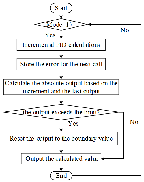
The PID calculation is done through the function PID_Compute (struct PID * PID_Rev_ch), which should be called periodically at each sampling period. The program flow of this function is as shown in Figure 15.
Figure 15. PID control flow
Motor speed acquisition uses the modified T method for speed detection, that is one time interval, time_test(us), is collected every six Hall pulses. The motor rotates half a cycle during this time interval so that the motor speed can be expressed as:
speed_pre = 30000000/time_test.
In order to calculate the time interval, the 32 bit unsigned global variable, os_clock, is defined. The running time of the system at any time can be obtained through the value of the variable os_clock and the count value of the timer 3. The following variable is defined as:
#define NOW os_clock*50000 + TIM_GetCounter(TIM3).
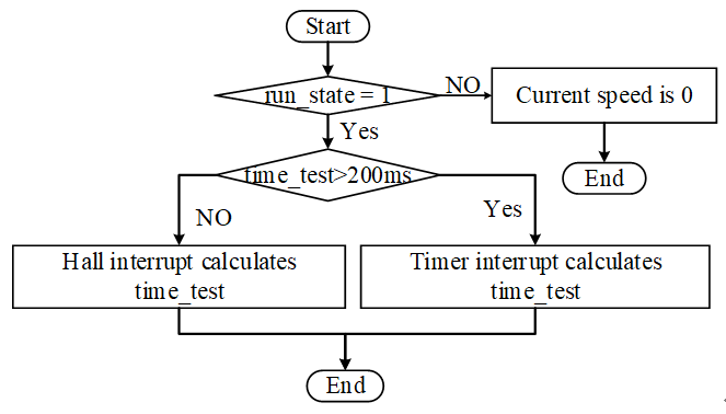
By calling the NOW variable, the motor speed acquisition program obtains the running time of the relative start-up state of the system. The motor will enter the Hall to capture interrupt during normal operation.The Hall code of each entry will be one of the 6 Hall states. The time interval is calculated only when the Hall code is 1, and the motor just rotates 6 Hall pulses the next time the Hall code is 1 again. Motor speed acquisition program flow is as shown in Figure 16.
Figure 16. Speed acquisition process
This paper designs the hardware circuit and driver program of the motor control system, which realizes the speed regulation and control of the 24V motor with 240W rated power or below in its starting up, ending and running. The driver is developed based on the STM32F103RC single chip microcomputer, which runs the UCOS-III real time system, and the starting up, commutation, and speed regulation of the motor, and the control, ending and reversal of PID speed closed-loop, and other programs are designed in this paper. It also designs an incremental PID control support library, simplifies the PID control program design, and achieves the setting of PID parameters of hub motor, thus the hub motor operates well in reality. On this basis, the control over the hub motor-driven robot can be realized by carrying the upper monitor and sending control commands through the CAN bus.
The authors acknowledge the financial support from science and technology innovation project of Shaanxi Province in China (No. 2015KTCQ02-12); the Fundamental Research Funds for the Central Universities (No. 2452016077), the Agricultural Science and Technology Innovation and Research project of Shaanxi Province (No. 2016NY-157). The authors also gratefully acknowledge the helpful comments and suggestions of the reviewers, which have improved the presentation.
Alexandridis A. T., Konstantopoulos G. C. (2014). Modified PI speed controllers for series-excited dc motors fed by dc/dc boost converters. Control Engineering Practice, Vol. 23, No. 2, pp. 14-21. https://doi.org/10.1016/j.conengprac.2013.10.009
Carlucho I., Paula D. M., Villar S. A., Acosta G. G. (2017). Incremental Q-learning strategy for adaptive PID control of mobile robots. Expert Systems with Applications, No. 80. https://doi.org/10.1016/j.eswa.2017.03.002
Chiu M. C., Yeh L. J., Lan T. S., Liao W. C. (2012). Ground-purity inspection for a group of robotic cleaners. Transactions- Canadian Society for Mechanical Engineering, Vol. 36, No. 2, pp. 161-176. https://doi.org/10.1139/tcsme-2012-0012
Cochrane W. A., Luo X., Lim T., Taylor W. D., Schnetler H. (2012). Design of a micro-autonomous robot for use in astronomical instruments. International Journal of Optomechatronics, Vol. 6, No. 3, pp. 199-212. https://doi.org/10.1080/15599612.2012.700550
Han J, Zhou H J. (2014). Wheeled mobile robot based on 51 single chip computer control system design. Advanced Materials Research, 846-847, 103-106. https://doi.org/10.4028/www.scientific.net/AMR.846-847.103
Li S., Gu H. (2012). Fuzzy adaptive internal model control schemes for pmsm speed-regulation system. IEEE Transactions on Industrial Informatics, Vol. 8, No. 4, pp. 767-779. https://doi.org/10.1109/TII.2012.2205581
Lu D. B., Ouyang M. G., Gu J., Li J. Q. (2012). Torque distribution algorithm for a permanent brushless DC hub motor for four-wheel drive electric vehicles. Journal of Tsinghua University, No. 4, pp. 451-456.
Lu D., Li J., Ouyang M., Gu J. (2012). Research on the control algorithm for brushless motor in four-wheel hub motor drive electric vehicle. 2011 IEEE Vehicle Power and Propulsion Conference, VPPC 2011. https://doi.org/10.1109/VPPC.2011.6043150
Shi J., Yu L. (2013). Simple expert PID speed control of ultrasonic motors. Proceedings of the CSEE, Vol. 33, No. 36, pp. 120-125.
Stel’makov V. N., Zhmurov V. P., Tarasov A. N. (2014). Thyristor-controlled phase-shifting devices. Russian Electrical Engineering, Vol. 85, No. 1, pp. 10-17. https://doi.org/10.3103/S1068371214010118
Su K. H, Chen Y. Y, Su S. F. (2010). Design of neural-fuzzy-based controller for two autonomously driven wheeled robot. Neurocomputing, Vol. 73, No. 13-15, pp. 2478-2488. https://doi.org/10.1016/j.neucom.2010.05.005
Xu Z. G., Shao C. (2009). Maximum efficiency control strategy of induction motor based on fuzzy logic. Control & Decision, Vol. 24, No. 5, pp. 743-748. https://doi.org/10.1360/972009-1551
Zhang H. F., Kang W. (2013). Design of the data acquisition system based on STM32. Procedia Computer Science, Vol. 17, No. C, pp. 222-228. https://doi.org/10.1016/j.procs.2013.05.030
Zhang T. M., Huang H., Huang P. H. (2014). Design and test of drive and control system for electric wheeled mobile car. Transactions of the Chinese Society of Agricultural Engineering, Vol. 30, No. 19, pp. 11-18.
Zhao B., Wang P. F., Hu H. Y., Sun L. N. (2011). Design of a spherical robot based on novel double ballast masses principle. High technology letters (English Edition), Vol. 17, No. 2, pp. 180-185. https://doi.org/10.3772/j.issn.1006-6748.2011.02.011
Zou J. B., Xu Y. X., Yu C. L. (2002). Novel detecting method of the rotor position of PMSM. Proceedings of the CSEE, Vol. 22, No. 12, pp. 47-51.