Dong Wang | Kai Pang* | Wei Wang | Yang Zhang | Wei Yao | Lei Zhao
© 2020 IIETA. This article is published by IIETA and is licensed under the CC BY 4.0 license (http://creativecommons.org/licenses/by/4.0/).
OPEN ACCESS
Through long-term operation, transformers often encounter internal faults. The traditional detection methods of these faults face several constraints, namely, limited space, heavy workload, and dense elements. To resolve these constraints, this paper designs an internal fault detection system for transformer based on wall-climbing robot. In the hardware part, the main controller receives the information captured by visual sensors, and controls the electromagnetic driving mechanism, such that the wall-climbing robot could walk against the walls inside the transformer and detect the internal defects. In the software part, socket programming was performed to design WIFI Connect, face recognition, and interface programs, providing a visual display and real-time transmission of fault information. Finally, our system was applied to detect the insulation discharge faults inside transformers of two substations. The fault locations of the two cases were quickly identified: shielding paper and corner ring for Case 1, and voltage regulating coil and iron core piece for Case 2. The results show that our system can detect the internal defects of transformer efficiently at a low cost. The research results shed new light on the intelligent, unmanned detection of internal faults of transformer.
internal faults, transformer, intelligent fault detection, socket programming
The safe and stable operation of the power grid is an important guarantee for production and life. In the power grid, transformer is one of the main equipment of power plants and substations. If any accident occurs in the transformer, the safety of the power grid will be undermined. A largescale power outage might ensue, causing huge direct and indirect economic losses [1-3].
With the development of large-capacity, ultra-high-voltage (UHV) power grid, the rate of transformer accidents is gradually on the rise. Statistics show that the mean accident rate of 330kV and 500kV transformers in China increased from 0.84% to 1.31% in terms of the number of accidents, and from 0.79% to 1.59% in terms of fault capacity [4].
Transformer faults fall into internal faults and external faults. Internal faults occur inside the fuel tank, including phase-to-phase short circuit, winding-to-turn short circuit, and single line-to-ground fault. External faults include phase-to-phase short circuit, and single line-to-ground fault between the insulation bushings of the lead wires [5]. Lots of data [6-9] have shown that transformer accidents mainly come from internal faults. For the operating stability of transformer, it is highly necessary to detect the internal faults.
Currently, the internal faults of transformer are mostly judged indirectly. Based on fusion technology, Lv et al. [10] developed a transformer fault diagnosis and information processing system. Hu et al. [11] improved the dissolved gas analysis (DGA), a conventional way to detect transformer faults, into a novel fault detection approach. Liu et al. [12] proposed a frequency response analysis strategy for detecting internal defects of transformers. However, the above detection methods cannot detect the fault type or locate the fault point in an accurate manner.
The regular detection of transformer faults faces several constraints, namely, limited space, heavy workload, and high cost. To judge the fault points, it is necessary to lift the transformer cover, or send a technician to enter the transformer [13]. This traditional approach increases the maintenance cost, and consumes too much time and energy.
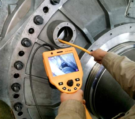
Industrial endoscopes have also been adopted to detect the inside of transformer (Figure 1). During the fault detection, a camera is sent to the vicinity of transformer winding via a flexible tube. Under the lighting of light-emitting diode (LED), the objective lens captures the light reflected by the object. The captured light is converted into video signals at the charge coupled device (CCD), and then transmitted to the monitor. In this way, operators can observe the inside of transformer accurately, without disturbing the transformer structure [14]. Nevertheless, the industrial endoscope is impractical for large transformers, due to the limited length and control difficulty of endoscope.
Despite the above practices, there is not yet a method that detects internal defects of transformer in a timely and accurate manner. Moreover, not much attention has been paid to internal detection robots for transformer [15]. Therefore, it is very meaningful to design a robot that can detect internal faults of transformer in replacement of technicians. Based on wall climbing robot, this paper develops an internal fault detection system for transformer. The hardware and software of the system were introduced in details. The proposed system was applied to detect the phase discharge fault of transformers. The results fully verify the detection effects of our system.
Figure 1. Internal fault detection of transformer using industrial endoscope
2.1 Hardware structure
Our internal fault detection system for transformer was developed based on an intelligent crawling robot with electromagnetic suction. As shown in Figure 2, the proposed system mainly consists of such modules as the main controller, the fault detection module, the Bluetooth module, the driving mechanism.
On top of the climbing robot, the three visual sensors collect images and temperature of the internal components of the transformer. The collected data are processed by the main controller, yielding the information about fault points. The electromagnetic suction wheels of the robot are driven by three independent modules, and each has a separate suspension structure. Hence, the climbing robot can work stably under various conditions, such as wall-climbing, obstacle crossing, and hanging upside down.
Figure 2. The overall architecture of the wall climbing robot
2.2 Main controller
The proposed system adopts an STM32F103VET6 main controller. The small controller is very suitable to be installed on a climbing robot. The power supply is 3.6-4.5V, the maximum power is 434mW, and the CPU frequency is 72MHz.
There is one USB interface and multiple I/O ports on the controller, resulting in a good compatibility. The controller receives and analyzes the signals from the visual sensors, thereby identifying the common internal faults of transformer.
The output signals of the main controller are transmitted via Bluetooth to control the motors of the driving mechanism. There are three L298N motor drivers, each of which can drive two loads on the driving mechanism. The driving mechanism outputs a voltage of 4.5V and a current of 30mA.
The main controller is powered by the DC generated by batteries. The original voltage (12V) is stepped down to 3.6-4.5V before being supplied to the main controller.
The main controller can be reset manually by pressing the Reset button. The reset operation can be completed at high level in 2 machine cycles. The reset signal should last for no less than 2ms, when the crystal frequency is 12MHz.
2.3 Visual sensors and fault detection module
The three visual sensors support both infrared thermal imaging and visible light imaging. The thermal sensitivity of the sensors is ultra high (0.06). During the detection by the wall-climbing robot, the components inside the transformer will radiate electromagnetic waves. If the temperature inside the transformer changes, the wavelength of the electromagnetic waves will vary accordingly. The visual sensors will transform the wavelength variation into temperature change, thereby measuring the internal temperature of the transformer.
If the temperature is abnormal, the abnormal data will be sent to the main controller. After analysis, the main controller will transmit the fault information to the fault detection module. Then, the fault information will be classified and displayed on the human-computer interface (HCI).
Figure 3. The 3D sketch map of the wall-climbing robot
Note: 1. Electromagnetic control board; 2. Pneumatic control valve; 3. Hinge; 4. Telescopic cylinder; 5. Visual sensors; 6. Pneumatic motor; 7. Communication interface; 8. Wire control board; 9. Electromagnetic suction wheels
As shown in Figure 3, three visual sensors are arranged at an interval of 120°. The arrangement could provide the wall-climbing robot with images and temperature inside the transformer continuously, during the walking process.
The visual sensors have pneumatic supports. The pneumatic motor drives the rotation of the vertical support column, which is connected by a hinge to the lateral support column. The lateral support column adopts a cylinder connection mechanism, which can stretch out and draw back horizontally according to the working conditions. The visual sensors are installed on the lateral support column.
Besides capturing temperature, visual sensors pass the path information to the main controller. When the wall-climbing robot faces an obstacle, the visual sensors will recognize the obstacle, and output the optimal path for the robot, with the aid of the path planning algorithm inside the main controller.
2.4 Driving mechanism
Since the servo of each L298N driver requires a voltage of 5V, an XL4015 switching step-down DC-DC converter chip was selected to convert the source voltage to 3V. With a fixed switching frequency of 180kHz, this chip helps to reduce the size of external components, and supply a stable operating voltage for the drivers.
The six DC motors are driven by the command from the main controller. Each motor has a gear set, which reduces the rotation speed of the wheels. The speed and position signals of the wheels will be fed back to the main controller through a potentiometer. On this basis, the main controller will determine the position and speed of each wheel.
The electromagnetic suction wheels all have an electromagnetic force. On average, each wheel produces a suction force no fewer than 30N. The structure of the driving mechanism is shown in Figure 4 below.
Figure 4. Working principle of the driving mechanism
2.5 Bluetooth module
The HC-05 Bluetooth module communicates with the main controller in two directions. The effective range of the module is 6m. Through Bluetooth communication, the path of the wall-climbing robot can be obtained at any time.
3.1 Function realization
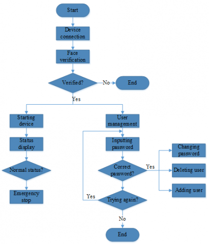
To monitor the internals of transformer intelligently, this paper designs an intelligent start-stop control system. As shown in Figure 5, the system mainly realizes the following functions: device connection, face verification, starting device, status display, stopping device, and user management.
The program of the intelligent start-stop control system covers three parts: WiFi connection program, face recognition program and interface program. The WiFi program connects the single-chip microcomputer (SCM) with the personal computer (PC). The face recognition program verifies the face of users, and allows the recognized users to start the system. The interface program realizes the HCI. The WiFi program is details as follows.
The WiFi program on the PC side mainly aims to set up the connection to the WiFi module on the SCM side, such that relevant commands can be sent to the SCM side. The main idea of the program is to create a class of WiFi Connect, and connect to the WiFi module on the SCM side via socket programming.
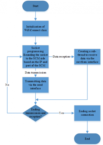
Specifically, a socket is created during class initialization, and bound to the SCM side through the IP/TCP protocol, according to the IP and port of the WiFi module on the SCM side. During data transmission, the commands are sent to the SCM side via the send interface of the socket. During data reception, a new thread is created, and the data from the SCM side are received at the PC side, using the recvfrom interface of the socket and the multi-threading technology. The workflow of socket programming is illustrated in Figure 6 below.
Figure 5. Overall structure of the intelligent start-stop control system
Figure 6. The workflow of socket programming
3.2 System test
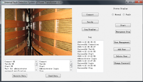
System test mainly verifies the overall function of the above software system. First, the “Connect” button on the Device Connection interface was clicked to connect the PC side to the SCM side via WiFi. Then, the system prompted “successful connection”. After that, the “Verification” button was clicked to launch face recognition. The system returned “Unknown” for the faces not found, returned “No Face” when no face was in the verification box, and returned user ID when the face was found in the system.
Once the user face was verified, the fuzzy “Start” button on the interface became clear, indicating that the system is ready to operate. Then, the “Start” button was clicked to start the internal monitoring of the transformer. The system promptly returned the start result after the button was clicked. After the system was started successfully, the status of the transformer was displayed in the status bar: normal or fault. Any fault being detected was shown in the bar and promoted to the user.
Figure 7. The interface of the control system
As shown in Figure 7, the administrator could add user, delete user, and change password on the User Management interface. After User Management was clicked, the system prompted the user to enter the password. When the input in the edit box differed from the preset password, the system promoted the user that he/she had entered a wrong password. When the input matched the preset password, the system returned “Correct password”. Once the “Add User” was clicked, the system prompted the user to place face to be added in the face frame. After clicking the prompt, the user must place the face in the frame, and wait for the system prompt “Face detected”. Once the “Delete User” was clicked, the system asked the user to select the users to be deleted.
The above software design and test improves the HCI of the internal fault detection system for transformer based on the wall-climbing robot. The intelligent start-stop control system makes it convenient for operators to manage the detection process, and enables the robot to walk freely in narrow space. In this way, it is more likely to detect the internal faults at a high accuracy.
To verify its effectiveness, the proposed internal fault detection system for transformer, which is based on the wall-climbing robot, was applied to two cases of transformer faults.
4.1 Case 1: C-phase discharge fault of Y/D UHV transformer II of a converter station
In the target converter station, the Y/D UHV transformer II entered operation in January 2014. The high-voltage bushing on the grid side of the transformer was replaced, because the acetylene was detected in the internal insulating oil of the bushing. After the replacement, the transformer was subjected to partial discharge test. Intermittent partial discharge signals were observed during the test, and the maximum grid-side discharge was 3,990pC. As shown in Table 1, the acetylene content increased significantly through the test. The fault location was not clear, despite multiple internal detections.
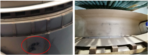
The proposed internal fault detection system was adopted to detect the fault inside the transformer. The collected photos (Figure 8) show multiple obvious discharge marks on the third shielding paper between the grid-side coil and voltage regulating coil of Coil II, and also between the first and second outermost corner rings on the upper end of the grid-side coil of Column II.
Table 1. The results of chromatographic test on insulating oil before and after partial discharge test (μL/L)
|
Sampling time |
CH4 |
C2H4 |
CH6 |
C2H2 |
H2 |
CO |
CO2 |
Total hydrocarbon |
Location |
|
20171101 Pre-test |
6.03 |
0.44 |
1.35 |
0.14 |
6.64 |
459.58 |
1,173.18 |
7.96 |
Top |
|
20171101 Pre-test |
6.03 |
0.42 |
1.29 |
0.16 |
6.26 |
448.37 |
1,129.57 |
7.9 |
Bottom |
|
20171102 Post-test |
7.08 |
1.82 |
1.45 |
4.09 |
16.54 |
333.56 |
706.23 |
14.44 |
Top |
|
20171102 Post-test |
6.19 |
0.67 |
1.24 |
0.98 |
9.71 |
350.89 |
740.94 |
9.08 |
Bottom |
Figure 8. The photos on shielding paper and corner rings
4.2 Case 2: Phase A discharge fault of main transformer #1 in a 500kV substation
Since its operation in 1988, phase A of main transformer #1 in the 500kV substation has witnessed a gradual growth in total hydrocarbon. In June 1990, acetylene content exceeded the alarm value (3%), and remained at that level. In April 1997, phase A was treated with oil, and added antioxidant T051 and activated alumina adsorbent. In December 1998, acetylene content surpassed the alarm value again. In October 2003, phase A was oil treated again. Since then, total hydrocarbon grew slowly, while the acetylene content stayed at a low level. As of December 2018, the gas content of phase A was 4.591%, greater than the alarm value, total hydrocarbon was 140.33μL/L, and acetylene content was 0.47μL/L.
On December 21, 2018, phases A, B, and C were subjected to DC resistance, insulation resistance, dielectric loss factor, capacitance, and no-load tests, but no abnormality was observed. On December 22, 2018, a partial discharge test was carried out on phase A of main transformer #1 in the 500kV substation. It was observed that the partial discharge amount exceeded the standard: under the test voltage of 1.3Um/ $\sqrt{3}$ , the maximum partial discharge reached 20,000pC at the medium and low voltage sides). After the test, there was a 0.1-0.2μL/L growth in acetylene content in the upper, medium, and lower parts of phase A, and a slight increase in total hydrocarbon (Table 2).
The test results, coupled with chromatographic data, indicate that discharge occurred in the transformer during the partial discharge test, but did not involve the solid insulation. During the test, no position of obvious discharge was detected by ultrasonic positioning. This is because the ultrasonic probe is not sensitive to the low-energy discharge source inside the transformer. Considering the discharge levels at high, medium, and low voltage sides, the discharge source was preliminarily positioned around the inner coil.
Table 2. The results of chromatographic test on insulating oil before and after partial discharge test (μL/L)
|
Sampling time |
CH4 |
C2H4 |
C2H6 |
C2H2 |
H2 |
CO |
CO2 |
Total hydrocarbon |
Sampling location |
|
2018.12.19Pre-test |
35.57 |
51.23 |
11.7 |
0.3 |
8.13 |
596.8 |
2,396.42 |
98.8 |
High |
|
47.86 |
68.11 |
15.71 |
0.41 |
10.63 |
822.09 |
3,201.61 |
132.09 |
Medium |
|
|
49.31 |
69.25 |
16.04 |
0.41 |
12.03 |
830.12 |
3,244.28 |
135.01 |
Low |
|
|
24h Post-test |
50.73 |
72.59 |
16.71 |
0.51 |
14.97 |
878.24 |
3,360.22 |
140.54 |
High |
|
56.39 |
77.57 |
17.71 |
0.53 |
17.8 |
984.14 |
3,585.77 |
152.2 |
Medium |
|
|
54.63 |
74.55 |
16.99 |
0.51 |
16.96 |
948.27 |
3,457.06 |
146.68 |
Low |
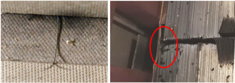
Figure 9. The photos on voltage regulating coil and core pieces
The proposed internal fault detection system was adopted to detect the fault inside the transformer. As shown in the collected photos (Figure 9), there was a thin metal wire between the bottom of the voltage regulating coil and the excitation coil (parallel to the low-voltage coil) on the side column of the main transformer; the side yoke (side column without coil), upper iron yoke, and core angle were obviously deformed in multiple places; the last core piece was displaced relative to the other core pieces.
This paper designs and implements an internal fault detection system for transformer based on wall-climbing robot, eliminating the need to send a technician into the transformer for fault detection. Three main conclusions were drawn through our research:
First, our internal fault detection system for transformer was developed based on an intelligent crawling robot with electromagnetic suction. Three visual sensors, which support both infrared thermal imaging and visible light imaging, capture the temperature and images inside the transformer in real time. The captured data are analyzed by the main controller, which then sends commands to the driving mechanism, which contains three wheels with electromagnetic suction.
This paper also designs an intelligent start-stop control system, which starts and controls the robot for internal defect detection through the HCI. Through this system, the fault information was visualized, compared with the stored information, and displayed on the monitor.
The proposed system was applied to detect the insulation discharge faults inside transformers in two substations. The fault locations of the two cases were quickly identified: shielding paper and corner ring for Case 1, and voltage regulating coil and iron core piece for Case 2. The results show that our system can detect the internal defects of transformer efficiently at a low cost.
This work is supported by the Scientific Technology Project of Electric Power Research Institute of State Grid Henan Electric Power Company.
[1] Mu, Y.B. (2014). Diagnosis and reasons analysis of winding deformation defects in 220kV transformer. Transformer, 51(011): 62-65.
[2] Li, X., Wang, Y.B., Huang, R.H., He, Z., Wu, G.X., Li, Z.G., Huang, W.Z. (2017). Structure design and analysis of oil-immersed transformer internal inspection robot. Mechanical Engineer, (3): 35-38. https://doi.org/10.3969/j.issn.1002-2333.2017.03.017
[3] Chen, H., Lu, X.C., Guo, T., Zhang, L., Wang, S. (2017). Dissolved gas analysis in power transformer oil and fault diagnosis. Northeast Electric Power Technology, 38(10): 29-32. https://doi.org/10.3969/j.issn.1004-7913.2017.10.009
[4] Ma, Y.L., Dong, Y.C., Teng, D. (2015). Analysis of transformer condition adjudgment based on gas chromatography method. Inner Mongolia Electric Power, 33(4): 27-30, 34. https://doi.org/10.3969/j.issn.1008-6218.2015.04.023
[5] Ma, J., Wang, Z.P., Zheng, S.X., Wang, T., Yang, Q.X. (2013). A new algorithm to discriminate internal fault current and inrush current utilizing feature of fundamental current. Canadian Journal of Electrical & Computer Engineering, 36(1): 26-31. https://doi.org/10.1109/CJECE.2013.6544469
[6] Patel, D., Chothani, N., Mistry, K. (2018). Discrimination of inrush, internal, and external fault in power transformer using phasor angle comparison and biased differential principle. Electric Power Components and Systems, 46(6-10): 788-801. https://doi.org/10.1080/15325008.2018.1509915
[7] Kari,·T., Gao, W.S., Zhang, Z.W., Mo, W., Wang, H., Cui, Y. (2018). Power transformer fault diagnosis based on a support vector machine and a genetic algorithm. Journal of Tsinghua University: Science and Technology, 58(7): 623-629. https://doi.org/10.16511/j.cnki.qhdxxb.2018.25.032
[8] Faiz, J., Soleimani, M. (2017). Dissolved gas analysis evaluation in electric power transformers using conventional methods a review. IEEE Transactions on Dielectrics & Electrical Insulation, 24(2): 1239-1248.
[9] Aizpurua, J.I., Catterson, V.M., Stewart, B.G., McArthur, S.D.J., Lambert, B., Ampofo, B., Pereira, G., Cross, J.G. (2018). Power transformer dissolved gas analysis through Bayesian networks and hypothesis testing. IEEE Transactions on Dielectrics and Electrical Insulation, 25(2): 494-506. https://doi.org/10.1109/TDEI.2018.006766
[10] Lv, Z., Zhou, Q., Zhou, K., Chen, L., Shen, S.K. (2015). Fault diagnosis of transformer based on extreme learning machine optimized by genetic algorithm. High Voltage Apparatus, 51(8): 55-59. https://doi.org/10.13296/j.1001-1609.hva.2015.08.008
[11] Hu, W.P., Yin, X.G., Zhang, Z., Chen, D.S. (2002). Transformer faults diagnosis and multi-sensor information fusion. High Voltage Engineering, 28(2): 32-36. https://doi.org/10.3969/j.issn.1003-6520.2002.02.014
[12] Liu, Y.P., Chen, H.H., Hu, H. (2019). Application of the complex values of the frequency response in fault diagnosis of power transformer. High Voltage Engineering, 55(7): 10-14. https://doi.org/10.13296/j.1001-1609.hva.2019.07.002
[13] Aggarwal, R.K, Mao, P. (1998). Digital simulation of the transient phenomena in high voltage power transformers with particular reference to accurate fault detection. International Conference on Simulation, York, UK. https://doi.org/10.1049/cp:19980669
[14] Hu, Y.D., Guo, H.B., Xie, M.Z. (2018). Analysis of transformer short-circuit fault based on capacitance-short-circuit impedance test and industrial endoscopy. Inner Mongolia Power Technology, 3606: 21-25.
[15] Liu, H.W., Wang, K., Lin, T., Zhou, X.Y. (2020). Fault detection method of transformer winding oscillatory wave based on discrete WAVELET. Transformer, 57(1): 58-62.