Mohamed Dahbi* | Said Doubabi | Ahmed Rachid
© 2020 IIETA. This article is published by IIETA and is licensed under the CC BY 4.0 license (http://creativecommons.org/licenses/by/4.0/).
OPEN ACCESS
Brushless DC motors are widely used due to many advantages such as high efficiency and low inertia. However, one of the main drawbacks of this motor type is related to the commutation current ripple. This paper deals with this issue encountered during brushless DC motor (BLDCM) control, by using a PI regulator implemented in upstream of the motor inverter. For this purpose, a BLDCM transfer function is established using identification toolbox system, based on a step voltage motor response, and further used to tune the regulator parameters. In this work, the duty ratio is varied twice, one time during commutation instant and the second time during the conduction period, in order to control the non-commutated phase current, presented as an image of the absorbed input current. This fact refers to commutated phases current slope control. Simulation results show a significant current ripple reduction for BLDCM which has also been confirmed using an experimental low-cost platform based on the Arduino Mega controller.
brushless DC motor, trapezoidal back-EMF force, PI controller, current ripple, current control
Brushless DC motors (BLDCMs) are widely used due to their several advantages among which we can cite high efficiency, high power-to-volume ratio, long lifespan, low cost of maintenance, low rotor inertia, etc. [1, 2]. These characteristics are mandatory for different applications such as aerospace and medical applications, in addition to electric transportation industry, where high speed, fast response and high precision position control are required.
BLDCM is a three-phase synchronous motor with permanent magnet rotor. As the name implies, the BLDCM does not use brushes for commutation, unlike the DC motor [3, 4]. In fact, the commutation is achieved electronically by a three-phase half-bridge inverter. This inverter is composed of electronic switches (MOSFETs, IGBTs, etc.) which are responsible for feeding the appropriate motor phases. This control requires rotor position knowledge, which is ensured by Hall Effect sensors.
BLDCM back-electromotive force (back-EMF) is trapezoidal in nature, which necessitates a Quazi-square current waveform for adequate control. The drive system of BLDCM is based on the Pulse Width Modulation (PWM) technique, where the motor speed is an image of the PWM signal duty ratio.
However, one of the main drawbacks of BLDCM is the commutation current ripple that generates unwanted system vibration and acoustic noises. The current ripple can occur either from the inverter switching, or from the motor manufacturing, or from the motor structure [5]. Referring to the control source, switching the current from one phase to another generates a current ripple phenomenon since the incoming and outgoing current slopes are not equal. This difference in the incoming and outgoing current slopes is also related to the motor speed.
Many researchers have proposed different methods to minimize current ripple to achieve high-motor performances. For instance, Ilhwan et al. have proposed methods based on modulating the incoming and outgoing phase current slopes at commutation period [6-8]. These methods differ in terms of current slope equalizing or falling and building up phase currents time equalizing. The efficiency of these methods, however, can be limited because, in some cases, one needs to distinguish between high and low speed operation. Besides, non- ideal variables of the BLDCM are also a source of the current ripple that has been alleviated by Lu et al. [9, 10]. These methods were developed for a non-ideal back-EMF and implemented based on PWM_ON_PWM mode of control [11-15].
Some other studies, Xia et al. have developed current ripple minimization methods based on predictive control. These studies improved the current phase’s shapes by selecting the optimal switching state at a sampling time and applying it during the next sampling period [16, 17].
Other works proposed current ripple reduction methods by controlling the DC-bus voltage at commutation periods [18-21]. They have used respectively Cuk, Sepic Z-source and buck DC-DC converter topologies, added in upstream of the BLDCM inverter to control the input voltage for the current ripple reduction and power factor correction. Some of these topologies have been compared in related research [22-24], in terms of BLDCM speed behavior and harmonics.
Multilevel inverters and modified converters topologies have also gained much attention for current ripple minimization. This is due to their advantages, compared to conventional topologies, such as less switching voltage stress and lower switching losses [25-28].
Nevertheless, using such control strategies needs additional devices and more adaptations of the global system. Moreover, to implement some of these control methods, a BLDC motor model is needed. Several models can be taken into consideration [29-31], however, all motor parameters are not always available or not well known, and sometimes it requires an advanced experimental platform for parameters identification.
To overcome such drawbacks, our motivations in this paper is to add further contributions to the state of the art by proposing a methodology and techniques for BLDCM modeling and control synthesis to minimize current ripple. Our low-cost method uses a PI regulator, which presents numerous advantages [32], and only one current sensor placed on the input of the motor inverter. The proposed BLDCM modeling method is established using Matlab identification toolbox (Ident) and was experimentally performed with motor current response for a step voltage, using an experiment designed platform, constituted from an out-runner BLDCM and Arduino-based controlled inverter.
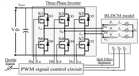
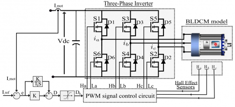
The BLDCM is a three-phase synchronous motor with trapezoidal back-EMF. Two phases are simultaneously conducting during each 60 electrical degrees. Since the DC-supply is a constant voltage source, using PWM control strategy has been implemented for speed variation and current control. Different modes of control can be implemented whether with the H_PWM-L_ON, H_ON-L_PWM, ON-PWM, PWM_ON or PWM-PWM, where the difference between these control modes is observed on the PWM controlled MOSFETs. The model of each BLDCM phase is simplified to a series connection of a phase resistance R, a phase inductance $L$ and a back-EMF $e_{x}(x=a, b \text { or } c)$. These phases are connected to a three-phase half bridge inverter as illustrated in Figure 1.
Figure 1. Model of BLDCM with three-phase half bridge inverter schematic
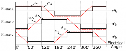
Controlling MOSFETs state (conducting or not) is related to the rotor position which is known using Hall Effect Sensors $\left(H_{a}, H_{b} \text { and } H_{c}\right)$. The current and back-EMF waveforms versus electrical degree $\theta_{e}$ are depicted in Figure 2, while Hall Effect sensors signals and triggered MOSFETs are presented in Table 1 and Table 2 respectively.
Figure 2. Phase current and Back-EMF waveforms of BLDCM
Table 1. Signal combination of Hall Effect sensors
|
Electrical degree θ (°) |
Hall Effect sensors signals |
|
0≤ θ<60 |
$\mathrm{H}_{\mathrm{a}}=1, \mathrm{H}_{\mathrm{b}}=0, \mathrm{H}_{\mathrm{c}}=0$. |
|
60≤θ<120 |
$\mathrm{H}_{\mathrm{a}}=1, \mathrm{H}_{\mathrm{b}}=1, \mathrm{H}_{\mathrm{c}}=0$. |
|
120≤ θ<180 |
$\mathrm{H}_{\mathrm{a}}=0, \mathrm{H}_{\mathrm{b}}=1, \mathrm{H}_{\mathrm{c}}=0$. |
|
180≤ θ<240 |
$\mathrm{H}_{\mathrm{a}}=0, \mathrm{H}_{\mathrm{b}}=1, \mathrm{H}_{\mathrm{c}}=1$. |
|
240≤ θ<300 |
$\mathrm{H}_{\mathrm{a}}=0, \mathrm{H}_{\mathrm{b}}=0, \mathrm{H}_{\mathrm{c}}=1$. |
|
300≤θ<360 |
$\mathrm{H}_{\mathrm{a}}=1, \mathrm{H}_{\mathrm{b}}=0, \mathrm{H}_{\mathrm{c}}=1$. |
Table 2. Triggered MOSFETs of the inverter
|
Electrical degree θ (°) |
Triggered MOSFETs |
|
0≤ θ<60 |
$S_{1}-S_{4}$ |
|
60≤θ<120 |
$S_{1}-S_{2}$ |
|
120≤ θ<180 |
$S_{3}-S_{2}$ |
|
180≤ θ<240 |
$S_{3}-S_{6}$ |
|
240≤ θ<300 |
$S_{5}-S_{6}$ |
|
300≤θ<360 |
$S_{5}-S_{4}$ |
Assuming that the phase resistances are equal, the phase inductances are constant, and the switching losses are neglected, the three-phase BLDCM voltage equation and Kirchhoff’s law can be expressed as (1) and (2):
$\left[\begin{array}{l}V_{a} \\ V_{b} \\ V_{c}\end{array}\right]=\left[\begin{array}{lll}R & 0 & 0 \\ 0 & R & 0 \\ 0 & 0 & R\end{array}\right]\left[\begin{array}{l}i_{a} \\ i_{b} \\ i_{c}\end{array}\right]+\left[\begin{array}{lll}L & 0 & 0 \\ 0 & L & 0 \\ 0 & 0 & L\end{array}\right] \frac{d}{d t}\left[\begin{array}{l}i_{a} \\ i_{b} \\ i_{c}\end{array}\right]+\left[\begin{array}{l}e_{a} \\ e_{b} \\ e_{c}\end{array}\right] +\left[\begin{array}{l}\hat{V}_{N} \\ V_{N} \\ V_{N}\end{array}\right]$ (1)
$i_{a}+i_{b}+i_{c}=0$ (2)
where, $i_{a}, i_{b}, i_{c}$ are the phase currents, and $V_{N}$ is the neutral voltage.
The developed electromagnetic torque $T_{e}$ and the speed motion equations are depicted in (3) and (4) respectively:
$T_{e}=\frac{e_{a} i_{a}+e_{b} i_{b}+e_{c} i_{c}}{w}$ (3)
$J \frac{d w}{d t}=T_{e}-T_{L}-B w$ (4)
where, $w$ is the rotor mechanical angular speed (rad/s), $T_{L}$ is the resistive load torque $(\mathrm{N} . \mathrm{m}), J$ and $B$ are respectively the moment of inertia (kg/m) and damping factor (N.m.s/rad) [33, 34].
As mentioned previously, two of the three phases are conducting. If we take, for example, the case where MOSFETs $S_{1}$ and $S_{4}$ are conducting, and the commutation is done when changing the state of MOSFETs $S_{4}$ and $S_{2}\left(S_{4}\right.$ becomes OFF \right. and $S_{2}$ becomes ON), the back-EMF of each phase is given as: $e_{a}=-e_{b}=-e_{c}=E,$ where $\mathrm{E}$ refers to the phase back-EMF amplitude. In this case, Eq. ( 3 ) becomes:
$T_{e}=\frac{2 E i_{a}}{w}=\frac{2 E I_{\text {mot }}}{w}$ (5)
where, $I_{\text {-mot }}$ refers to the current absorbed from the DC power voltage.
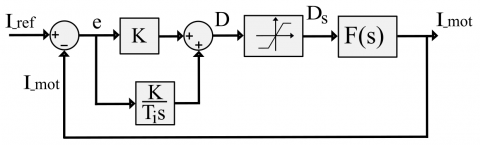
Figure 3. Current regulation using PI regulator block diagram
From (5), it can be shown that torque ripple (and consequently the current ripple) is related to the non-commutated phase. Hence, controlling the current ripple refers to controlling the non-commutated phase current, which denotes a control of the absorbed current from the DC-supply. Implementing a PI regulator to avoid such current ripple will be discussed in the next section using a BLDCM transfer function F(s) obtained from an experimental step response and Matlab system identification toolbox. Figure 3 illustrates the current regulation block-diagram. F(s) will be stated more specifically in the next section.
$\mathrm{K}$ and $\mathrm{T}_{\mathrm{i}}$ denote the PI controller proportional and integral parameters, respectively. D is the duty ratio calculated by the controller, $\mathrm{D}_{s}$ is the saturated duty ratio, $\mathrm{e}$ is the error between measured current $I_{-\text {mot }}$ and its reference $I_{\text {ref }},$ and $I_{\text {-mot }}$ is the response of the motor by duty ratio $\mathrm{D}_{s}$.
In order to perform experimental tests, an experiment platform has been designed using a low-cost micro-controller namely Arduino Mega board (Figure 4). It is composed of IRFP260 MOSFETs as semiconductor switches controlled by IR2110 drivers, and an ACS712-20A current sensor to measure the absorbed current. Data acquisition was done using a National Instrument NI USB-6259 card. Table 3 presents the BLDCM parameters.
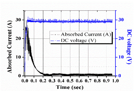
The BLDCM current response was acquired for a step voltage from 0V to 28V. Figure 5 presents the current and the voltage waveforms.
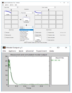
Using the system identification Toolbox Ident of Matlab, based on nonlinear least square estimation method, the transfer function coefficients were extracted as shown in Figure 6. Changing the order of the obtained transfer function is an advantage given by the used method. In our case, a second order model showed close response with the experimental one.
Figure 4. Designed test-rig
Figure 5. Experimental current and voltage waveforms
Table 3. BLDCM Parameters
|
Parameters |
Value |
|
Power |
500W |
|
Voltage |
48V |
|
Speed |
500rpm |
|
Resistance |
0.25 Ω |
|
Inductance |
9e-4 H |
|
Torque constant |
1.1 |
Figure 6. System identification editor windows
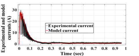
The resulting transfer function, where the system input is the DC voltage and the output is the absorbed current from the DC supply, is presented in Figure 7, while Figure 8 presents the simulation and experimental results for the same input (a step voltage from 0V to 28V).
Figure 7. Transfer function representation for the used BLDCM
Figure 8. Model and experimental responses for a step voltage input from 0V to 28V
The results given by the transfer function and experimental data are in concordance. This transfer function is used for synthetizing the PI regulator. However, providing a zero by the PI regulator in the closed-loop transfer function can change the transient state of the system. To remedy this problem, the poles compensation method is more adapted for the PI regulator computation parameters. It consists on imposing the regulator zero equal to one pole of the controlled system transfer function in addition to a constant of time $\tau$ meeting the objectives set. Still, the numerator of the closed loop transfer function is related to parameters $\mathrm{K}$ and Ti. Hence, we chose to add trial \& error method for PI corrector tuning.
The chosen parameters, $\mathrm{K}=10$ and $\mathrm{T}_{\mathrm{i}}=200$ are the implemented values in what follows. Those parameters are implemented for simulation purpose to use them after for practical acquisition. The next section will present the global system, comprising in addition to the elements presented in Figure $1,$ the PI regulator and the current reference.
MATLAB/Simulink environment was used to evaluate the proposed method in terms of BLDCM current ripple reduction. The proposed current ripple minimization controller was implemented for two different speeds, 100 and 200 rpm, using the synoptic presented in Figure 9.
Figure 9. Regulation synoptic
Simulation results are depicted in Figures 10 and 11 with and without the proposed method.
From Figures 10 (a) and 11 (a), the phase current is presenting current ripples due to the outgoing and incoming commutating time mismatch. The proposed method allowed the suppression of such undesirable current ripples like presented in Figures 10 (b) and 11 (b).
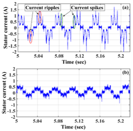
The effectiveness of the proposed control method is validated through experimental tests carried out using the platform presented in Figure 4. The obtained results are illustrated in Figures 12 and 13.
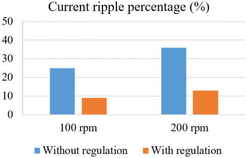
From the previous results, it can be noticed that the phase currents are presenting significant current ripples in addition to current spikes before commutation instant. These current spikes can be explained by the not perfect positioning of the Hall Effect sensors on the brushless motor stator. Implementing the DC input current regulation has shown an important reduction of the current ripples and even current spikes. Figure 14 shows current ripple percentages with and without the proposed method. The reduction of current ripple is significant: 16% for 100 rpm and 23% for 200 rpm.
Figure 10. Simulation results of phase current for 100 rpm motor speed: (a) with conventional motor control, (b) with the proposed method
Figure 11. Simulation results of phase current for 200 rpm motor speed: (a) with conventional motor control, (b) with the proposed method
Figure 12. Experimental results of phase current for 100 rpm motor speed: (a) with conventional motor control, (b) with the proposed method
Figure 13. Experimental results of phase current for 200 rpm motor speed: (a) with conventional motor control, (b) with the proposed method
Figure 14. Current ripple percentages with and without using the proposed method
In this paper, a novel method of brushless DC motors modeling, using MATLAB system identification toolbox, for current ripple minimization is proposed.
A PI regulator modifies the MOSFETs duty ratio to control the absorbed DC current during conduction and commutation periods. This fact makes incoming and outgoing phase currents respectively increase and decrease with the same slope during the commutation period. Hence, commutation current ripple is minimized, which induces a low torque ripple.
The proposed method has the advantage of less components and does not require sophisticated platforms, since one current sensor is the only added device for such modeling and control purposes. Simulation results have shown significant current ripple reductions, and experimental validation was established using a low cost design BLDCM controller. This latter has presented a reduction of 12% and 23% of commutation current ripple respectively for 100 rpm and 200 rpm motor speeds when compared to conventional control method.
The authors acknowledge the financial support received from the INSTITUTE FOR RESEARCH IN SOLAR ENERGY AND NEW ENERGY (IRESEN) - VERES Project, and their encouragement in carrying out this college work.
[1] Ahmed, M.Y. (2018). Operation of electric vehicle traction system. European Journal of Electric Engineering, 5(2): 51-57. https://doi.org/10.18280/mmep.050201
[2] Dahbi, M., Doubabi, S., Rachid, A., Oulad-Abbou, D. (2020). Performance evaluation of electric vehicle brushless direct current motor with a novel high-performance control strategy with experimental implementation. Proceedings of the Institution of Mechanical Engineers, Part I: Journal of Systems and Control Engineering, 234(3): 358-369. https://doi.org/10.1177/0959651819854562
[3] Yin, S. (2019). Estimation of rotor position in brushless direct current motor by memory attenuated extended Kalman filter. European Journal of Electric Engineering, 21(1): 35-42. https://doi.org/10.18280/ejee.210106
[4] Dahbi, M., Doubabi, S., Rachid, A. (2018). Current spikes minimization method for three-phase permanent magnet brushless DC motor with real-time implementation. Energies, 11(11): 3206-3219. https://doi.org/10.3390/en11113206
[5] Salah, W.A., Ishak, D., Hammadi, K.J. (2011). Minimization of torque ripples in BLDC motors due to phase commutation-a review. Przeglad Elektrotechniczny, 87(1): 182-188.
[6] Kim, I., Nakazawa, N., Kim, S., Park, C., Yu, C. (2010). Compensation of torque ripple in high performance BLDC motor drives. Control Engineering Practice, 18(10): 1166-1172. https://doi.org/10.1016/j.conengprac.2010.06.003
[7] Kim, J.H., Park, J.S., Youn, M.J., Moon, G.W. (2011). Torque ripple reduction technique with commutation time control for brushless DC motor. 8th International Conference on Power Electronics - ECCE Asia, Jeju, 2011, pp. 1386-1391. https://doi.org/10.1109/ICPE.2011.5944417
[8] Salah, W.A., Ishak, D., Zneid, B.A., Abu_Al_Aish, A., Jadin, M.S., Sneineh, A.A. (2015). Implementation of PWM control strategy for torque ripples reduction in brushless DC motors. Electrical Engineering, 97(3): 239-250. https://doi.org/10.1007/s00202-014-0329-7
[9] Lu, H., Zhang, L., Qu, W. (2008). A new torque control method for torque ripple minimization of BLDC motors with un-ideal back EMF. IEEE Transactions on Power Electronics, 23(2): 950-958. https://doi.org/10.1109/TPEL.2007.915667
[10] Fang, J., Li, H., Han, B. (2011). Torque ripple reduction in BLDC torque motor with nonideal back EMF. IEEE Transactions on Power Electronics, 27(11): 4630-4637. https://doi.org/10.1109/TPEL.2011.2176143
[11] Meng, G., Xiong, H., Li, H. (2009). Commutation torque ripple reduction in BLDC motor using PWM _ ON PWM mode. 2009 International Conference on Electrical Machines and Systems, Tokyo, pp. 1-6. https://doi.org/10.1109/ICEMS.2009.5382974
[12] Chuang, H.S., Ke, Y., Chuang, Y.C. (2009). Analysis of commutation torque ripple using different PWM modes in BLDC motors. Conference Record 2009 IEEE Industrial & Commercial Power Systems Technical Conference, Calgary, AB, pp. 1-6. https://doi.org/10.1109/ICPS.2009.5463966
[13] Liu, M. Guo, H. Song, M. (2012). Ripple torque analysis and simulation of BLDC motor with different PWM modes. Proceedings of the 7th International Power Electronics and Motion Control Conference, Harbin, 2012, pp. 973-977. https://doi.org/10.1109/IPEMC.2012.6258927
[14] Wei, K., Ren, J., Teng, F., Zhang, Z. (2004). A novel PWM scheme to eliminate the diode freewheeling in the inactive phase in BLDC motor. 2004 IEEE 35th Annual Power Electronics Specialists Conference, Aachen, Germany, pp. 2282-2286. https://doi.org/10.1007/s11460-006-0019-y
[15] Zhou, M., Li, Z., Gu, Q., Xu, Z., Xu, H. (2013). Influence of PWM modes on non-commutation torque ripple in brushless DC motor control system. Proceedings of 2013 2nd International Conference on Measurement, Information and Control, Harbin, pp. 1004-1008. https://doi.org/10.1109/MIC.2013.6758129
[16] Xia, C., Wang, Y., Shi, T. (2013). Implementation of finite-state model predictive control for commutation torque ripple minimization of permanent-magnet brushless DC motor. IEEE Transactions on Industrial Electronics, 60(3): 896-905. https://doi.org/10.1109/TIE.2012.2189536
[17] Chen, Y., Tang, J., Cai, D.S., Liu, X. (2012). Torque ripple reduction of brushless DC motor on current prediction and overlapping commutation. Przegląd Elektrotechniczny (Electrical Review), 88(10a): 247-253.
[18] Chen, W., Liu, Y., Li, X., Shi, T., Xia, C. (2017). A novel method of reducing commutation torque ripple for brushless DC motor based on Cuk converter. IEEE Transactions on Power Electronics, 32(7): 5497-5508. https://doi.org/10.1109/TPEL.2016.2613126
[19] Kumar, C.S., Kumar, N., Radhika, S.P. (2014). Torque ripple minimization in BLDC motor using DC-DC SEPIC converter. Przegląd Elektrotechniczny (Electrical Review), 90(9): 146-150.
[20] Li, X., Xia, C., Cao, Y., Chen, W., Shi, T. (2016). Commutation torque ripple reduction strategy of Z-source inverter fed brushless DC motor. IEEE Transactions on Power Electronics, 31(11): 7677-7690. https://doi.org/10.1109/TPEL.2016.2550489
[21] Sarala, P., Kodad, S.F., Sarvesh, B. (2017). Power factor correction with current controlled buck converter for BLDC motor drive. International Journal of Power Electronics and Drive Systems, 8(2): 730-738. http://dx.doi.org/10.11591/ijpeds.v8.i2.pp730-738
[22] Renius, A.J.S., Kumar, K.V. (2015). Analysis of variable speed PFC chopper FED BLDC motor drive. International Journal of Power Electronics and Drive Systems, 5(3): 326-335. http://dx.doi.org/10.11591/ijpeds.v5.i3.pp326-335
[23] Suryoatmojo, H., Nandiwardhana, A.P., Arsya, N.R., Anam, S., Putra, H.P., Mardiyanto, R., Ashari, M. (2016). Comparisons of Cuk, SEPIC and Zeta converter performance for harmonics mitigation and PFC in BLDC speed control. 2016 International Seminar on Intelligent Technology and Its Applications (ISITIA), Lombok, pp. 681-686. https://doi.org/10.1109/ISITIA.2016.7828742
[24] Ramesh, V., Kusuma, L.Y. (2015). Comparison between an interleaved boost converter and CUK converter fed BLDC motor. International Journal of Power Electronics and Drive System (IJPEDS), 6(3): 594-602. http://dx.doi.org/10.11591/ijpeds.v6.i3.pp594-602
[25] Viswanathan, V., Seenithangom, J. (2017). Commutation torque ripple reduction in the BLDC motor using modified SEPIC and three-level NPC inverter. IEEE Transactions on Power Electronics, 33(1): 535-546. https://doi.org/10.1109/TPEL.2017.2671400
[26] Amirthalingam, R., Mahadevan, B. (2017). A new approach for minimizing torque ripple in a BLDC motor drive with a front end IDO dc-dc converter. Turkish Journal of Electrical Engineering & Computer Sciences, 25(4): 2910-2921. https://doi.org/10.3906/elk-1605-40
[27] Gu, C., Wang, X., Deng, Z. (2017). Torque ripple suppression method for brushless DC motor based on instantaneous-bus-voltage control strategy. 2017 IEEE Applied Power Electronics Conference and Exposition (APEC), Tampa, FL, pp. 532-538. https://doi.org/10.1109/APEC.2017.7930745
[28] Raja, M.S., Geethalakshmi, B. (2016). Analysis and implementation of a high boost ratio DC-DC converter for minimizing commutation torque ripple in brushless DC motor. International Journal of Power Electronics and Drive System (IJPEDS), 7(2): 583-600. http://dx.doi.org/10.11591/ijpeds.v7.i2.pp583-600
[29] Ghany, M.A., Shamseldin, M.A., Ghany, A.A. (2017). A novel fuzzy self tuning technique of single neuron PID controller for brushless DC motor. 2017 Nineteenth International Middle East Power Systems Conference (MEPCON), Cairo, pp. 1453-1458. https://doi.org/10.1109/MEPCON.2017.8301374
[30] Nag, T., Acharya, A., Chatterjee, D., Ganguli, A.K., Chatterjee, A. (2015). An efficiency optimization scheme for BLDC motor drive system. International Journal of Power Electronics and Drive Systems, 6(4): 869-875.
[31] Shanmugasundram, R., Zakaraiah, K.M., Yadaiah, N. (2013). Modeling, simulation and analysis of controllers for brushless direct current motor drives. Journal of Vibration and Control, 19(8): 1250-1264. https://doi.org/10.1177/1077546312445200
[32] El Alaoui, E.C., Ayad, H., Doubabi, S. (2006). Fuzzy anti-windup schemes for PID controllers. International Journal of Applied Engineering Research, 1(3): 295-306.
[33] Yadav, P., Poola, R., Najumudeen, K. (2016). High dynamic performance of a BLDC motor with a front end converter using an FPGA based controller for electric vehicle application. Turkish Journal of Electrical Engineering & Computer Sciences, 24(3): 1636-1651. https://doi.org/10.3906/elk-1401-289
[34] Khubalkar, S., Junghare, A., Aware, M., Das, S. (2017). Modeling and control of a permanent-magnet brushless DC motor drive using a fractional order proportional-integral-derivative controller. Turkish Journal of Electrical Engineering & Computer Sciences, 25(5): 4223-4241. https://doi.org/10.3906/elk-1612-277