Saber M. Saleh* | Asmaa S. Farag
OPEN ACCESS
Direct grid connection without the requirement of power electronics using fixed speed wind turbine control strategies is proposed in this paper. Review two control strategies are adopted to obtain fixed rotational speed for the squirrel cage generator and achieve the objective of the FSWT system. The first control system is a conventional PI-controller applied to the gearbox ratio. The simulation results prove the robustness of the system and the possibility of obtaining constant voltage and constant rotational speed which will lead to a constant frequency at their rated value irrespective of the wind speed. Therefore, it can be connected with the grid without the requirement of power electronics. The second control strategy is by varying the excitation capacitor value with the wind speed. However, this method is limited to a certain range for the wind speed variation which is from 5 to 16 m/s. The simulation results show the achievement of the constant speed for grid connection purpose. The proposed strategies are simple, rigid, and fulfillment for cage generator. In addition, the disadvantage of the FSWT, this is its incapability of achieving maximum power in all wind speeds. The simulation proved that the variation of power coefficient with values below its maximum value under the variation of wind.
fixed speed wind turbine (FSWT), gear ration control, excitation capacitor control, realistic wind model, squirrel cage generator
Recently, wind power is a fully established branch on the electricity market and it is treated accordingly. The energy gain is not the only criteria to be considered when installing new wind turbines; cost efficiency, the impact on the environment and the impact on the electric grid are some important issues of significant interest when making decisions about new wind turbine installations. So as energy yield is important, also is price, and there are various ways in which manufacturers seek to achieve the best balance between high yield and low price. For the wind energy conversion system (WECS) to be cost-effective, future wind turbines must be designed with lighter, more flexible components (blades, drive train, tower, etc.) that reduce their weight and cost. As the wind turbines become more flexible and larger, structural dynamic loads and instabilities will be increased unless the control systems are specifically designed to mitigate these loads and dynamic interactions. And hence, many control methods have been developed during the last decade for the WECS [1]. The operation of the wind turbines makes noisy environments, they present a myriad of control problems that, if solved, could reduce the cost of wind energy. The control system for a wind turbine is important with respect to both machine operation and power production. Efficient and reliable control strategies are required to make the WECS more profitable. Independent the kind of wind turbine (WT), control systems play a key role in the regulation of the output power, increasing the efficiency and extending the turbine life which leads to the decrease in energy costs. The objective of the control design for WTs is to optimize the captured wind energy. For this purpose, there are many choices of architecture available to the designer of a WT and most of these have been explored over the years. Several designs of WTs have their own advantages and disadvantages. However, commercial designs for electricity generation have now converged to a horizontal axis, three-bladed, upwind turbines [2]. At one hand of the spectrum are the simple and rugged stall-regulated WTs, running at FS and using induction generators where controls are incorporated to hold or adjust rotational speed. On the other hand, are the VS, direct-drive machines with power conditioning equipment are the main objective is to maximize power. The Horizontal-axis wind turbine (HAWT), therefore, operates in two modes namely constant or variable speed. HAWT is classified to a fixed speed (FSWT) and variable speed (VSWT) [3].
There are many previous attempts to design or control the direct grid connection. Slip synchronous permanent magnet wind generator direct-drive based on finite element optimization program used for permanent magnet synchronous Machine (PMSM) [4]. The inverter control method used to grid-connected WT based PMSM included in [5]. Rotor position estimation sensorless control used to control doubly-fed induction generator (DFIG) direct grid connection [6–8]. PMSM Nonlinear multi-input-multi-output controller used to generate the converter control signal for direct grid connection [9]. Active DC-link multiport converter strategy is used for PMSM grid connection [10]. All these methods of control concern with PMSM or DFIG while the proposed technique used for cage generator.
This paper focuses on the FSWT conversion system. The control system components and different control systems for the WT are introduced in section 2. The control strategies to obtain FS at the generator side are explained in section 3. Section 5 introduces the simulation results for each case of control and shows how the constant speed and hence constant frequency are obtained. Section 6 concludes the paper.
The operational turbine control that achieves the control objectives for regions below rated wind speed (Region2) and above rated wind speed (Region3) which includes generator torque control (GTC), blade pitch control (BPC), and yaw control. Generator torque control performed using the power electronics. The extracted torque opposes the aerodynamic torque provided by the wind and, thus, indirectly regulates the turbine speed. Depending on the pitch actuators and type of generator and power electronics, BPC and GTC can operate quickly relative to the rotor-speed time constant. Yaw control, which rotates the nacelle to point into the wind, is slower than GTC and BPC. Due to its slowness, yaw control is of less interest to control engineers than GTC and blade pitch angle control.
The control methods developed for WECS include fixed-speed (FS), variable-speed (VS), and variable pitch turbine which are of the most important from the control perspective. In FSWT, electric power which is the output is not controlled since it has no options for control input and the output is easily influenced by larger disturbance of the WS, thus, this type has less electric power and worse quality. Then the VSWT was developed. This last type is more attractive than the FS due to flicker problem reductions, and the WT can operate at maximum power point for various wind speeds by adjusting the shaft speed at the optimal one for keeping the maximal power coefficient (Cp) at all wind velocities. However, the electric power output becomes upper than the nominal power when the speed of wind is higher than the rated wind speed, which obliges stopping the WT to protect the generator from extra power.
Majority of machines run at FS and use induction generators (the rotor and generator rotational speeds are held constant actually within a speed range about 1 %), but increasing numbers run at VS, using power conditioning equipment. The largest machines tend to operate at VS whereas smaller, simpler turbines are of FS. The most commonly used concepts are FSWTs equipped with asynchronous or induction generators and are considered the oldest and simplest concepts [11].
The FSWT is a self-controlled concept. With increasing wind speed the laminar wind current flow around the fixed blade profile breaks and the turbine lose the possibility to obtain energy from the wind, the turbine stalls. In the proposed scheme, the induction electric generator stator's circuit (which transforms the obtained mechanical energy into electrical energy) is connected directly to the grid. The rotor shaft is almost locked with the frequency of the electrical grid. The speed of the generator may vary only a small percent from its nominal value according to the generator torque characteristic due to the slip variation of the generator, which is up to 1 %. Benefits of FSWT are the simplicity of the system but at the same time having the possibility of flicker regulation and load minimization especially at high wind speeds.
Fixed speed operation means that regardless of the WS, the rotor speed is fixed. By studying the Equation (1) for the TSR indicates that the TSR for FSWT varies across a wide range depending on the speed of the wind. Then the performance coefficient Cpm and consequently the maximum output power is optimal only at one specific wind speed. For FSWT, the rotor turns at constant angular speed regardless of wind variations. The FSWT eliminates expensive power electronics such as inverters and converters. So, it is simple, robust, reliable, and the cost of its electrical parts is low. Its disadvantage is limited rotor speed so that the WT cannot operate at its peak efficiency in all WSs. For this reason, FSWT produces less energy at low WSs than does a VSWT which is designed to operate at a rotor speed proportional to the WS below its rated value [12].
$\mathrm{TSR}=\lambda=\frac{\mathrm{v}_{\mathrm{t}}}{\mathrm{v}_{\mathrm{w}}}=\frac{\omega_{\mathrm{t}} \mathrm{R}}{\mathrm{v}_{\mathrm{w}}}$ (1)
where vt is the tangential speed of the blades at the tips, ωt is the angular rotational speed of the turbine rotor in (mechanical rad/s), R is the outer radius of the wind turbine in (m), and vw is the undisturbed (free) wind speed in the site in (m/s).
Due to its simplicity, most traditional wind turbines operate at fixed speed except the starting and stopping situations. The FSWTs became the standard WT with stall controlled blades for several decades. During the 1980s and 1990s large scale WTs operated at FS.
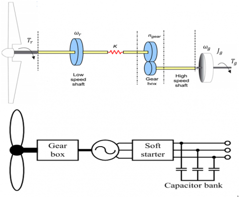
A typical FSWT conversion system consists of simple devices which are an aerodynamic rotor driving a low-speed shaft, a gearbox, a high-speed shaft and an IG that connected directly to the network through soft-starter and a capacitor bank for reducing reactive power compensation. A general configuration of FSWT system is shown and illustrated in Figure 1.
Figure 1. Layout of fixed speed wind turbine principal
The induction generator used in the generation of wind power is becoming more popular. However, the IG with a squirrel cage rotor lacks a self-excited source especially in an isolated energy system (our case study) and consequently can't generate the reactive power needed for power generating. Therefore, an induction generator for isolated systems must have a capacitor parallel connected to the output terminal (known as SEIGs) to provide the reactive power and use the capacitor exciter. The capacitor bank also designed to compensate for the induction generator no-load reactive power consumption since SCIG consume reactive power and hence provide a power factor correction. Another common part is a gearbox that is because the rotational speed of the WT is always lower than the generator speed. An economically feasible multi-pole induction machine design applicable to wind power applications has not been found so far [13]. Finally, a soft starter function is to build up the magnetic flux slowly and so minimize transient currents during energization.
The speed of the wind variation affects the operation speed of the wind generator, and then it will influence the rotation speed of the induction generator rotor to be driven. This phenomenon will lead to the variation of an output voltage and frequency accordingly, such that the normal rated power can't be outputted and the utilizing of induction generator is lowered.
Two control strategies have been developed for the system under study. The first of these is the active controller, which adjusts the ratio of the gearbox and thus keeps the high-speed shaft constant at the generator side irrespective of the speed of the wind and consequently, the stator frequency is constant. The second controller is the reactive controller which adjusts the switching capacitor bank at the value that performs constant speed and adjusts the terminal voltage at the rated value. Both controllers are implemented as follows.
4.1 Gearbox ratio strategy
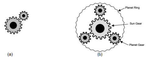
The slow wind speed needs the gearbox increases the WT rotor rotational speed to that which is appropriate for the generator. The parallel gear is simply two gearwheels situated next to each other where the rotational energy is transformed into the other gear as in Figure 2 (a). Planetary gear consists of a Sun gear in the middle and three planet gear evenly placed around the Sun gear as in Figure 2 (b). Around the planets is a Planet ring (or Planet carrier) which holds the gears in place. The Planet ring is also toothed on the inside where it carries the planet gear. The planetary gear is somewhat more complex but has some advantages. A great advantage of the planetary gear is that made very compact and weight can be reduced. This is owing to the fact that there are three gears in contact with the sun wheel all the time, and they share the stresses and the forces. There will be a proper torque without extra linear forces which would appear in a parallel gear type. One disadvantage with the planetary gear stage is that a more complex design makes the gearbox more vulnerable [14].
a) parallel gear b) planetary gear
Figure 2. Types of gearbox
The gearbox rotation speeds $\mathrm{n}_{1} \& \mathrm{n}_{2}$ and the number of teeth $\mathrm{d}_{1} \& \mathrm{d}_{2}$ related by the following equation:
$n_{g}=\frac{d_{1}}{d_{2}}=\frac{n_{2}}{n_{1}}=\frac{\omega_{g}}{\omega_{t}}=\frac{T_{t}}{T_{g m}}$ (2)
where $n_{g}$ the gear ratio, $\omega_{g}$ is the generator angular speed at the high speed shaft in (rad/s) and $T_{ g m}$ is the generator electromechanical torque or the turbine mechanical torque after transferred to the high speed shaft in (N.m).
The multistep gain of the series gearboxes equal to the product of the individual gains [15].
In this work, the control strategy will control the gearbox ratio with respect to the speed of the wind to obtain constant speed at the high-speed shaft which drives the generator. And consequently, the generator rotational speed is maintained constant irrespective the wind speed. Therefore, the box with different gears to obtain the suitable gear ratio connected to the generator.
The algorithm used to control maintaining the generator rotational speed (ωr) constant with the variation of the wind speed. The controller of the present study can be applied by using a Proportional-Integral (PI) controller which contains two variable gains the first gain is proportional gain KP and the second gain is integral gain KI. Generator speed error input to the PI controllers and then the output of the PI controller regulates the rotor of wind turbine speed which in turn tune up the gearbox ratio that maintains the high-speed shaft at its rated value and hence, the generator speed. Then the PI controller can be expressed as follows:
$\omega_{t}=k_{p} e+k_{i} \int e d t$ (3)
$\mathrm{e}=\omega_{\mathrm{r}}-\omega_{\mathrm{r}-\mathrm{ref}}$ (4)
where $\omega_{\mathrm{r}-\mathrm{ref}}$ is the reference rotational speed.
The PI controller gains are determined using trial and error method and the parameters are achieved during the simulation.
4.2 Excitation capacitor strategy
The other control strategy used to maintain the generator speed constant is the excitation capacitor value (C). In the case of the FSWTs with conventional induction generators, the reactive power can be controlled by switching the capacitor bank. The rotor speed of the generator and the capacitance value are related by the following equation.
$C_{\min }=\frac{1}{\omega_{r}^{2} L_{m}}$ (5)
But, according to the magnetization current im the Lm value is not constant. Therefore, the excitation capacitor value related to the speed of the wind to obtain constant $\omega_{r}$ is obtained by simulating the model several times for different wind speed. However, the excitation capacitor value variations achieve good performance only for wide speed varying in the range from 5 to 16 m/s. This simulation result values fitted as a polynomial of degree 5. The excitation capacitance in farad as a function of wind speed is given as:
$C=-3.365 \times 10^{-8} v^{5}+1.637 \times 10^{-6} v^{4}-3.198 \times$$10^{-5} v^{3}+0.0003132 v^{2}-0.001438 v+0.0026$ (6)
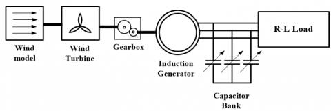
The proposed WECS is simulated using the Matlab/Simulink package. The schematic diagram of the under testing standalone wind turbine based SEIG is shown in Figure 3.
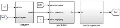
Also, the overall Matlab/Simulink model of the proposed system shown in Figure 4 is with their subsystems which have been introduced in [16, 17]. The model with assumed zero pitches angles in this case.
Figure 3. Schematic diagram for the system under study
Figure 4. SIMULINK model of SEIG with realistic wind turbine
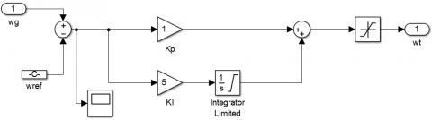
The first controller strategy is applied in which the ratio of the gearbox is adjusted by a conventional PI controller. The Simulink of the PI controller shown in Figure 5 with controller gains Kp=1 and KI=5.
Figure 5. Simulink model of the PI controller
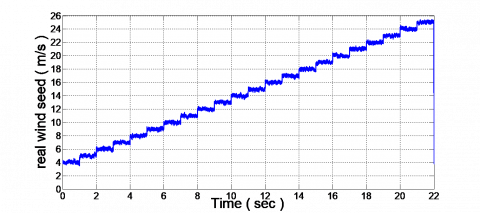
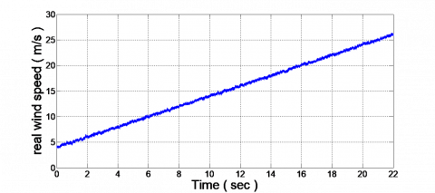
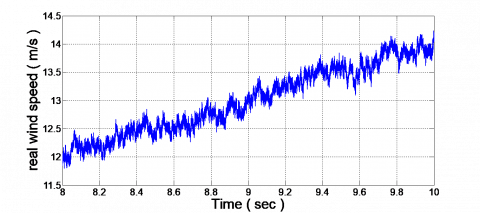
In order to study the response of the system, different wind speed values for are used starting from the cut-in speed (V=4 m/s) up to the cut-out speed (V=25 m/s) under realistic wind speed model. The realistic wind speed corresponding to different means values of wind speeds shown in Figure 6. Figure 6 introduces two strategies for variation response of the wind speed from 4 up to 22 m/s.
Figure 6. Realistic wind speed from 4 up to 22 m/s
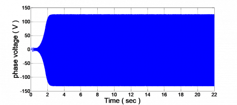
Figure 7. The generated voltage under wind speeds varied from 4 to 22 m/s
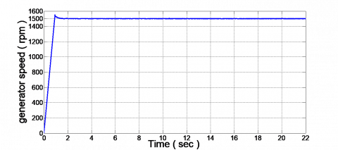
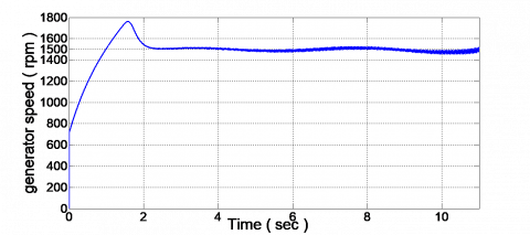
Figure 8. The generator rotational speed under wind speeds varied from 4 to 22 m/s
The generated stator voltage under a range of real wind speeds from 4 to 22 m/s shown in Figures 7 and 8.
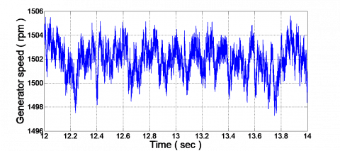
The stator voltage as shown in Figure 7 is balanced, constant and maintained at its rated value. Also, the rotational speed is constant irrespective of wind speed value. However, it is not entirely constant and there are some variations that shown in Figure 8. However, the generator speed may vary only a small percent from its nominal value which is up to 1 %. The rated generator speed under study is 1500 rpm and 50 HZ, so 1 % represents about 15 rpm. Our result in Figure 8 shows that the variation is about 6 rpm which represents 0.4 % from the rated value. This type of wind generation is normally referred to as fixed speed.
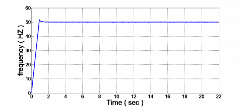
Figure 9. The frequency of the system under wind speeds varied from 4 to 22 m/s
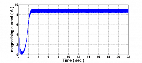
Figure 10. The magnetizing current under wind speeds varied from 4 to 22 m/s
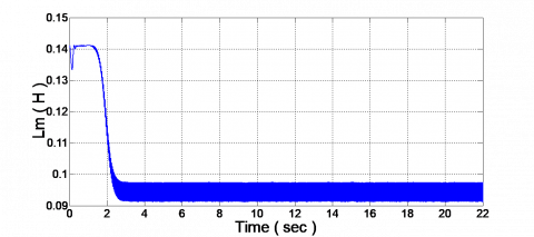
Figure 11. The magnetizing inductance under wind speeds varied from 4 to 22 m/s
Figure 12. Load current under wind speeds varied from 4 to 22 m/s
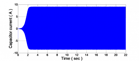
Figure 13. The excitation capacitor current under wind speeds varied from 4 to 22 m/s
The frequency characteristic, magnetizing current, magnetizing inductance, load current, and capacitor current are plotted in Figures 9-13.
A plot for the gearbox ratio variation response according to the wind speed variation from 4 to 22 m/s shown in Figure 14.
Figure 14. The gearbox ratio variation response with wind speed variation
The simulation result of the generator speed for the second controller strategy in which controlled the value of the excitation capacitor to obtain FSWT operated at its rated value 1500 rpm shown in Figure 15.
Figure 15. The generator rotational speed under wind speeds variation from 5 to 16 m/s
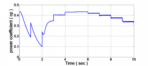
As discussed previously, the main disadvantage of FSWT conversion system is that it can't operate at its maximum efficiency in all wind speeds. However, the maximum value of the performance coefficient Cpm and consequently the maximum output power is achieved only at one specific wind speed (the rated speed). For all other wind speeds, a lower coefficient of performance is observed in Figure 16, which introduces the power coefficient plot under different wind speed for the proposed FSWT system.
Figure 16. The power coefficient variation as wind speed varied
For FSWTs, Review two control strategies are adopted to obtain fixed rotational speed for the generator, constantly generated voltage and achieve the objective of the FSWT system. The first one was a conventional PI-controller used to adjust the gearbox ratio. However, the second was varying the excitation capacitor value with respect to the speed of the wind. This method is limited to a certain range of wind speed from 5 to 16 m/s. The simulation results prove the robustness of the system and the possibility of obtaining constant voltage and constant rotational speed which will lead to a constant frequency at their rated value irrespective of the speed of the wind. The disadvantage of the FSWT is it can't capture the maximum power as proved by the simulation results because the power coefficient Cp doesn't attend its maximum value for wind speeds vary below the rated speed.
[1] Bianchi, F.D., de Battista, H., Mantz, R.J. (2007). Wind Turbine Control Systems: Principles, Modelling and Gain Scheduling Design. Springer-verlag, London Limited.
[2] Wu, B., Lang, Y.Q., Zargari, N., Kouro, S. (2009). Power Conversion and Control of Wind Energy Systems. Hoboken, New Jersey, John Wiley & Sons.
[3] Rivkin, D.A., Toomey, K., Silk, L. (2013). Wind Turbine Technology and Design. USA, Jones& Bartlett learning, LCC.
[4] Potgieter, J.H.J., Kamper, M.J. (2015). Design optimisation of directly grid-connected PM machines for wind energy applications. IEEE Transactions on Industry Applications, 51(4): 2949-2958. https://doi.org/10.1109/TIA.2015.2394506
[5] Jéssica S., Guimarães1, Bruno Ricardo de Almeida1, Fernando Lessa Tofoli, Demercil de Souza Oliveira Jr. (2018). Three-phase grid-connected WECS with mechanical power control. IEEE Transactions on Sustainable Energy, 9(4): 1508-1517. https://doi.org/10.1109/TSTE.2018.2792942
[6] Swami Naidu, N.K., Singh, B. (2017). Grid-interfaced DFIG-based variable speed wind energy conversion system with power smoothening. IEEE Transactions on Sustainable Energy, 8(1): 51-58. https://doi.org/10.1109/TSTE.2016.2582520
[7] Chinmaya, K.A., Singh, G.K. (2019). Modeling and experimental analysis of grid-connected six-phase induction generator for variable speed wind energy conversion system. Electric Power Systems Research, 166: 151-162. https://doi.org/10.1016/j.epsr.2018.10.007
[8] Mishra, A., Tripathi, P.M., Chatterjee, K. (2018). A review of harmonic elimination techniques in grid connected doubly fed induction generator based wind energy system. Renewable and Sustainable Energy Reviews, 89: 1-15. https://doi.org/10.1016/j.rser.2018.02.039
[9] Housseini, B., Okou, A.F., Beguenane, R. (2018). Robust nonlinear controller design for on-grid/off-grid wind energy battery-storage system. IEEE Transactions on Smart Grid, 9(6): 5588-5998. https://doi.org/10.1109/TSG.2017.2691707
[10] St-Onge, X.F., Richard, C., McDonald, K.M., Saleh, S.A.S. (2018). Performance testing of an active multi-port DC-link for grid-connected PMG-based WECSs. IEEE Transactions on Industry Applications, 54(6): 5579-5589. https://doi.org/10.1109/TIA.2018.2850298
[11] Wu, Q.W., Sun, Y.Z. ed. (2018). Modeling and Modern Control of Wind Power. Hoboken, USA, John Wiley & Sons Ltd.
[12] Ackermann, T. Ed. (2005). Wind Power in Power Systems. Chichester, West Sussex, England, Hoboken, NJ: John Wiley.
[13] Ofualagba, G. (2012). Analysis of the dynamic characteristics of an isolated self-excited induction generator driven by a wind-turbine. International Journal of Scientific & Engineering Research, 2(2): 1-10.
[14] Stiebler, M. (2008). Wind Energy Systems for Electric Power Generation. Berlin: Springer.
[15] Manwell, J.F., McGowan, J.G., Rogers, A.L. (2009). Wind Energy Explained: Theory, Design and Application. 2nd ed. Chichester, U.K: Wiley.
[16] Saleh, S.M. (2016). Study of wind turbine based self-excited induction generator under nonlinear resistive loads as a step to solve the Egypt electricity crisis. Computers and Electrical Engineering, 51: 1-11. https://doi.org/10.1016/j.compeleceng.2016.02.018
[17] Saleh, S.M., Farag, A.S., El-Bayoumi, G. (2017). Pitch control dynamic study of isolated wind turbine based self-excited induction generator under realistic wind speed profiles. Nineteenth International Middle East Power Systems Conference (MEPCON), Menoufia University, Egypt. https://doi.org/10.1109/MEPCON.2017.8301212