Qian Chen | Gang Lv* | Ruiliang Zhang | Huadong Tang | Zongyuan Luo
OPEN ACCESS
The automatic transmission of high-frequency voltage signals under remote control is critical to the stable operation of the power system. To prevent corona discharge and partial discharge accidents, it is necessary to enhance the ability of the transmission lines to resist electromagnetic interference and line spectrum disturbance. Therefore, this paper proposes and improves an output channel model for the automatic transmission of high-frequency voltage signals under remote control. Drawing on adaptive spectrum feature extraction and equalization filtering, the proposed model combines non-stationary time series analysis, linear equalization and fractionally-spaced equalization to improve the balance of voltage signal transmission. The results of simulation experiment show that our method minimized the bit error rate (BER) of the communication system, achieved good channel equalization, ensured high fidelity of output symbols, and enhanced the resistance to multipath interference. The research findings shed new light on improving the quality of high-frequency voltage signals in transmission lines under remote control.
transmission lines, transmission signals, optimization, high-frequency voltage, suppression
High-frequency voltage transmission has become an important way to transmit electric power over a wide range in China, thanks to its strong transmission capacity, long transmission distance and huge economic benefits. It is of great significance for the construction of smart grid. As the power grid covers more and more areas, the transmission lines of the grid must have stronger ability to control the high-frequency voltage transmission [1-3].
To transmit the voltage signals on the transmission lines automatically, the networking of transmission lines should be optimized, and the communication channels be equalized [4]. On this basis, the transmission control of high-frequency signals can be optimized using channel equalization design, interference filtering methods, plus the optimal control of the communication interfaces. In this way, the reception and transmission of high-frequency voltage signals can be controlled in a more accurate manner. In general, the automatic transmission design of high-frequency voltage signals directly hinges on the analysis of filter performance and the calculation of steady-state fixed-value of components [5].
Under remote control, the automatic transmission of high-frequency voltage signals is traditionally facilitated by fast Fourier transform (FFT) filtering [6], adaptive filtering [7], multi-bandpass filtering [8], and cascaded second-order infinite impulse response (IIR) notch filtering with fixed coefficient [9]. These filtering methods generally design an ideal frequency selective filter based on the spectral features of the target signals, and realize the accurate transmission of signals through spectral feature analysis and interference signal suppression.
Ding et al. [10] designs an adaptative filter to suppress the interference in high-frequency voltage communication. During the input process, if statistical features are unknown or dynamically changing, the filter dynamically will adjust its parameters by a specific algorithm to meet a certain criterion (e.g. the least mean squared error (MSE)), and then drive the estimates of the useful input signals and the error signals eliminated by the filter. In other words, when the statistical features change dynamically in the input process, the adaptive filter will adjust its parameters to track these changes, thus optimizing the output signals. However, the main disadvantage of the least mean squares (LMS) algorithm is the slow convergence. To speed up the convergence, the step size must be increased, but a large step size will increase and even diverge the steady-state value of the MSE. If the interference has a single frequency and a narrow band, the optimal step size can be obtained through repeated simulations. Nevertheless, the online monitoring of partial discharge often faces multiple narrowband interferences at the same time, which differ greatly in frequency (from tens of kHz to a few MHz), making it difficult to select the parameters of the adaptive filter.
Li et al. [7] develops an adaptive filtering algorithm based on wavelet decomposition, carries out simulation analysis on partial discharge signals, and processes the field data. The results show that this algorithm bolsters the system ability to suppress narrowband periodic interference, and further improves the stability of the adaptive filtering algorithm, enhancing its application value. The defect of this algorithm lies in the heavy computing load.
Based on Gaussian filter interference suppression, Helmy et al. [11] proposes an automatic transmission method for high-frequency voltage signals under remote control. Coupling matched filter detection and power spectrum analysis, the proposed method realizes the automatic transmission for high-frequency voltage signals under remote control, and improves the equalization and stationarity of signal output channels of the transmission lines. On the downside, the algorithm faces a high computing overhead and a poor real-time performance of signal output.
Considering the defects of existing methods, this paper puts forward an automatic transmission technology for high-frequency voltage signals based on adaptive spectral feature extraction and equalization filtering. Firstly, the high-frequency voltage signals and their transmission channels were both modelled. Next, the signal interference filtering was performed and the channel equalization design was prepared, thus optimizing the automatic transmission of high-frequency voltage signals. Finally, a simulation experiment was conducted to prove the superiority of our technology in enhancing the ability of transmission lines to transmit high-frequency voltage signals automatically under remote control.
2.1 Channel modelling
The non-stationary time series analysis [12] was adopted to model the transmission of high-frequency voltage signals under remote control, aiming to optimize the transmission process and improve the channel equalization. The first step is to construct a model for the transmission channels. During the transmission of high-frequency voltage signals, the channel equalization depends on both bandwidth and frequency. The channels need to be equalized in the light of the transmission distance of the line. Therefore, the adaptive link forwarding protocol was applied to optimize the networking design of the transmission lines [13], enhancing the automatic forwarding and control of voltage signals. Through the modelling of high-frequency voltage signals under remote control, the bandwidth of a transmission line for high-frequency voltage signal transmission can be obtained as:
$g(t)=\sqrt{s}f(s[t-\tau ])$ (1)
where, f(t) is the feature component of high-frequency signals in the output voltage; s=(c-v)/(c+v) is the time scale factor (called scale for short) about the scaling of high-frequency voltage signals under remote control; τ=2R/c, with R being the radial distance between high-frequency voltage transmission nodes; $\sqrt { s }$ is the normalization factor.
Then, continuous wavelet transform was applied to the real signal x(t) of high-frequency voltage. Taking scale a and translation b as independent variables, the spatial-spectral feature components Sx and interference components Kxof the transmission of high-frequency voltage signals under remote control can be obtained by time-frequency feature decomposition:
${{S}_{x}}=E\left[ {{x}^{3}}(t) \right]+\sqrt{s}bu[s(t-{{\tau }_{0}})]$ (2)
${{K}_{x}}=E\left[ {{x}^{4}}(t) \right]-3{{E}^{2}}\left[ {{x}^{2}}(t) \right]b$ (3)
where, E[x3(t)] is the frequency-domain attenuation features of the transmission path for the high-frequency voltage signals; b is the voltage gain. The time-frequency decomposition [14] was carried out to control the gain of the transmission channels. Then, the continuous transform of the output gain y(t) of the channels relative to the phase deviation ψ(t) of the voltage signals can be described as:
${{W}_{\psi }}y(a,b)=<y,{{\psi }_{a,b}}>=\int\limits_{-\infty }^{+\infty }{y(t)\frac{1}{\sqrt{\left| a \right|}}{{\psi }^{*}}(\frac{t-b}{a})dt}$ (4)
taking the wavelet family ψa,b as the carrier signal and ψ(t) as the dependent variable, the instantaneous power spectral density of the high-frequency voltage signals outputted by the transmission line can be computed by spectral correlation detection:
${{\psi }_{a,b}}(t)=\left[ U(a,b)\psi (t) \right]=\frac{1}{\sqrt{\left| a \right|}}\psi (\frac{t-b}{a})$ (5)
where, U(a,b) is the unitary transformation of the signals; ${1}/{\sqrt{\left| a \right|}}\;$ is the factor ensuring the energy normalization of the unitary transformation. Based on the structure of the unitary transformation, the time-frequency analysis was carried out to compute the impulse response function of each channel. Then, the channel equalization control was adopted to enhance the adaptivity of signal transmission [15].
2.2 Signal analysis
Based on channel modelling, the next step is to analyze the signal features. Here, the carrier signal f(t) of the high-frequency voltage is taken as the mother wavelet. Assuming that a=1/s and b=τ, the delay spread loss of high-frequency voltage signals in a transmission line under remote control can be described as:
${{f}_{s,\tau }}(t)=\left[ U(1/s,\tau )f(t) \right]=\sqrt{\left| s \right|}f(s(t-\tau ))$ (6)
Under remote control, the channel environment for transmission of high-frequency voltage signals is very complicated. In general, the following two conditions must be satisfied: cjTc<Tf and $\forall j\in [0,{{N}_{f}}-1]$. Through the spectral analysis based on the delay spread, the complex envelope of the high-frequency voltage signals under broadband carrier frequency can be obtained as:
$u(t)=\frac{1}{\sqrt{T}}rect(\frac{t}{T})\exp \{-j[2\pi K\ln (1-\frac{t}{{{t}_{0}}})]\}$ (7)
where, rect(t)=1, |t|≤1/2. Let h(n) be the impulse response in the transmission channels of high-frequency voltage signals under remote control. Then, the frequency-modulating function of the output high-frequency components is a hyperbolic function:
${{f}_{i}}(t)=\frac{K}{{{t}_{0}}-t}\begin{matrix} {} & |t|\le \frac{T}{2} \\\end{matrix}$ (8)
where, K=Tfmaxfmin (fmin and fmax are the minimum and maximum frequencies, respectively) and t0=f0T/B are the width and initial sampling time of the sampled spectrum of high-frequency voltage signals, respectively; f0 is the arithmetic mean frequency of the high-frequency components of the voltage signals. Then, the adaptive spectral decomposition was performed to extract the instantaneous power spectral density of high-frequency voltage signals. Thus, the high-frequency voltage signals can be scaled on the time scale (Figure 1).
Figure 1. Scaling of high-frequency voltage signals on the time scale
As shown in Figure 1, the scaling of high-frequency voltage signals includes time-frequency decomposition and feature compression. The high-frequency voltage signals under remote control were processed sequentially, and the bind source features were separated in the neighborhood of the center timepoint. Then, the instantaneous power spectral density of the high-frequency voltage signals can be determined as:
$\begin{align} & {{W}_{u}}u(a,b)={{e}^{j2\pi K\ln a}}\times \frac{K}{\sqrt{a}}\left\{ \left[ \frac{a{{e}^{\frac{j2\pi {{f}_{\min }}}{a}(b-{{b}_{a}})}}}{{{f}_{\min }}}-\frac{{{e}^{j2\pi {{f}_{\max }}(b-{{b}_{a}})}}}{{{f}_{\max }}} \right] \right. \\ & \quad \quad \quad \quad \quad +j2\pi (b-{{b}_{a}})\left[ Ei(j2\pi {{f}_{\max }}(b-{{b}_{a}})) \right.-\left. \left. Ei\left( \frac{j2\pi {{f}_{\min }}}{a}(b-{{b}_{a}}) \right) \right] \right\} \\\end{align}$ (9)
where, ${{b}_{a}}=(1-a)(\frac{1}{a{{f}_{\max }}}-\frac{T}{2})$; $Ei(\bullet )$ is the energy of the voltage signals. According to the extracted spectral features, the automatic transmission of high-frequency voltage signals was optimized by signal spectral decomposition, time-frequency analysis, signal filtering and channel equalization design.
3.1 Interference filtering
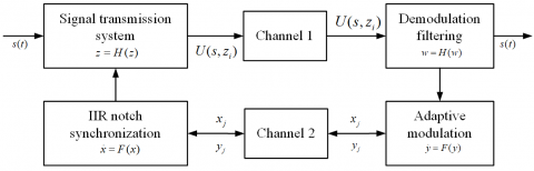
In the preceding section, the transmission of high-frequency voltage signals under remote control has been modelled, and the relevant signal features have been analyzed. On this basis, this section attempts to optimize the automatic transmission of these signals. The proposed automatic transmission technology for high-frequency voltage signals takes basis on adaptive spectral feature extraction and equalization filtering. The matched filter detection method was employed to filter the interferences in the high-frequency voltage signals. The structure of the interference filter model is presented in Figure 2.
Figure 2. The structure of the interference filter model
Let nÎ[n1,n2] be the interval of high-frequency voltage transmission in the automatic signal transmission model. Then, an autocorrelation matched filter was constructed to suppress multi-component interferences. For a high-frequency voltage signal on the scale of a, t was replaced with t/a. Then, the phase function of the transmission of high-frequency voltage signals can be expressed as:
$\theta (t)=2\pi \int_{-T/2}^{t/a}{(\frac{K}{{{t}_{0}}-{t}'})d{t}'}=-2\pi K\ln (1-\frac{t}{a{{t}_{0}}})+{{\theta }_{0}}$ (10)
where, ${{\theta }_{0}}=-2\pi K\ln (1+\frac{T}{2{{t}_{0}}})$. Then, the modulation frequency of the filter can be described as:
${{f}_{{{i}_{a}}}}(t)=\frac{1}{2\pi }\frac{d\theta }{dt}=\frac{K}{a{{t}_{0}}-t}=\frac{K}{{{t}_{0}}-t+(a-1){{t}_{0}}}$ (11)
where the subscript ia is the instantaneous frequency of the wavelet function on the scale of a. Hence, the relationship between the instantaneous output frequency and the input phase can be established as:
${{f}_{{{i}_{a}}}}(t)={{f}_{i}}[t-(a-1){{t}_{0}}]$ (12)
suppose
${{b}_{m}}={{t}_{0}}(1-a)$ (13)
The modulation frequency of the signal output can be obtained by the matched filter detection method:
${{f}_{{{i}_{a}}}}(t)={{f}_{i}}(t+{{b}_{m}})$ (14)
Then, the phase equalization control was performed on the time scale according to the scale of the signals. In this way, the relationship between the spectral component and the amplitude of the signal output can be established as:
${{u}_{a}}(t-{{b}_{m}})=\frac{1}{\sqrt{a}}u(t)-\frac{aT}{2}+{{b}_{m}}<t<\frac{aT}{2}+{{b}_{m}}$ (15)
On the scale-translation plane, the filtered output of the high-frequency voltage signals at point (a,bm) can be expressed as:
${{W}_{u}}u(a,{{b}_{m}})=\frac{1}{\sqrt{a}}\int_{-T/2}^{T/2}{u(t){{u}^{*}}(\frac{t-{{b}_{m}}}{a})dt}=\frac{1}{\sqrt{a}}\int_{-aT/2+{{b}_{m}}}^{T/2}{u(t)u*(t)dt}=\frac{1}{\sqrt{a}}\int_{-aT/2+{{b}_{m}}}^{T/2}{{{\left| u(t) \right|}^{2}}dt}$. (16)
Therefore, the matched filter detection method can effectively suppress the noise components in high-frequency voltage signals and promote the ability of the transmission lines to transmit signals automatically.
3.2 Channel equalization and automatic transmission optimization
Based on the interference suppression, the output spectral components of the high-frequency voltage signals can be obtained as:
${{W}_{u}}u(a,{{b}_{m}})=\frac{1}{\sqrt{a}}\int_{-aT/2+{{b}_{m}}}^{T/2}{{{\left| \frac{1}{\sqrt{T}} \right|}^{2}}dt}=\frac{1}{\sqrt{a}T}(\frac{T}{2}+\frac{aT}{2}-{{b}_{m}})$ (17)
Substituting the initial sampling frequency t0 into (17), we have:
${{W}_{u}}u(a,{{b}_{m}})=\frac{1}{\sqrt{a}T}\left( \frac{T}{2}+\frac{aT}{2}-\frac{(1-a){{f}_{0}}T}{B} \right)=\frac{1}{\sqrt{a}}\left( \frac{a+1}{2}-\frac{(1-a){{f}_{0}}}{B} \right)$. (18)
The channel equalization of the high-frequency voltage signals was implemented by linear equalization [15] and fractionally spaced equalization [16]. Taking a>1, the output impulse response of the voltage signals can be obtained as:
${{W}_{u}}u(a,{{b}_{m}})=\frac{1}{\sqrt{a}}\left( \frac{a+1}{2}-\frac{(a-1){{f}_{0}}}{B} \right)$ (19)
In the time-frequency plane, the instantaneous frequency of the high-frequency voltage signals was computed as fi(n). Through horizontal filtering, the spectrum form of the output voltage signals after the equalization can be described as:
${{W}_{u}}u(a,{{b}_{m}})=\frac{1}{\sqrt{a}}\left( \frac{a+1}{2}-\frac{\left| a-1 \right|}{B/{{f}_{0}}} \right)$ (20)
Furthermore, the output coupling of the transmission of high-frequency voltage signals was controlled by ensemble statistic feature analysis, and the channel spectrum was enhanced by line enhancement. In this way, the spectral feature component of the high-frequency voltage signals was obtained as $\left| V({{e}^{j\omega }}) \right|=1$ and the channel equalization output was determined as $V({{e}^{j\omega }})={{e}^{j\Phi (\omega )}}$. Through the above steps, this paper successfully optimizes the automatic transmission technology of high-frequency voltage signals under remote control. The workflow of the optimized algorithm is shown in Figure 3 below.
Figure 3. The workflow of the optimized algorithm
The proposed method was verified through a simulation experiment on the automatic transmission of high-frequency voltage signals under remote control. The high-frequency voltage signals were generated by an AWG2015 signal generator. The algorithms to process the signals were programmed on MATLAB 7. The transmission control and features of the high-frequency voltage signals were analyzed in Simulink, a MATLAB-based graphical programming environment.
The simulation parameters were configured as follows: the number of sampling points for the high-frequency voltage signals, N=125; the SNR of the interferences, -10~10dB; the initial sampling frequency of high-frequency voltage signals, 100 kHz; the final sampling frequency of high-frequency voltage signals, 200 kHz; the length of the signal sample, 1,024; the size of the sample set, 100; the carrier bandwidth, 12.7 dB; the sampling interval of the received signals, 2,400 symbols; the order of the equalizer, 3.
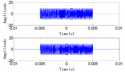
Based on the above parameters, the automatic transmission of high-frequency voltage signals was simulated under remote control. The waveforms of the signals collected at the transmitting end and the receiving end are displayed in Figure 4.
Figure 4. The waveforms of the signals collected at the transmitting end and the receiving end
The signals in Figure 4 were taken as the test sample. Then, the matched filter detection was performed to suppress the interferences and the channel equalization was conducted. The spectral components in the impulse response of the resulting signals is shown in Figure 5.
(a) Transmitting end
(b) Receiving end
Figure 5. The spectral components in the impulse response of high-frequency voltage signals
As shown in Figure 5, the proposed method output highly focused spectral components in the impulse response of high-frequency voltage signals at the receiving end, and greatly suppressed the interference beams. This means our method can effectively enhance the ability of the transmission lines to transmit signals and to resist interferences.
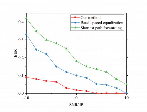
Furthermore, our method was compared with two traditional transmission methods for high-frequency voltage signals, namely, baud-spaced equalization and shortest path forwarding, in terms of bit error rate (BER) in output signals. The comparison results in Figure 6 show that, with the increase in the SNR of the input voltage signals, the BERs of all methods exhibited a decline. When the input SNR reached 4dB, the output BER of our method decreased to zero. The mean BER of our method was 23.6% lower than that of baud-spaced equalization and 18.9% lower than that of shortest path forwarding. Thus, the transmission ability for high-frequency voltage signals can be effectively improved by our method.
Figure 6. Comparison between three transmission methods in terms of BER
This paper designs and optimizes an automatic transmission technology for high-frequency voltage signals under remote control. Based on adaptive spectrum feature extraction and equalization filtering, the proposed technology ensures the fidelity, anti-interference and quality of the high-frequency voltage signals being transmitted. Drawing on adaptive spectrum feature extraction, the time scale of the signals was adjusted through channel equalization control, adaptive spectral decomposition and time-frequency analysis, outputting a model of the transmission channels. Inspired by equalization filtering, the interferences were suppressed and the channels were equalized by linear and fractionally-spaced equalization methods. This strategy effectively suppresses the noise components in high-frequency voltage signals, promotes the ability of the transmission lines to transmit signals automatically, and enhances the channel spectrum. The results of simulation experiment show that our method performed well in the automatic transmission of high-frequency voltage signals under remote control, in that it effectively reduced the output BER, and improved the fidelity and anti-interference of the high-frequency voltage signals.
This work is supported by the scientific project of Guiyang Bureau of UHV Transmission Company, China Southern Power Grid Co., Ltd.
[1] He, J.H., Liu, L. (2017). A fast state estimation algorithm for intelligent distribution network based on decoupling transformation. Proceedings of the CSEE, 37(4): 1088-1095.
[2] Aboelazm, Y.M., Wahba, W.E., Moustafa Hassan, M.A. (2018). Simulation of advanced STATCOM for voltage swell mitigation in large-scale test system based on swarm intelligence algorithms. European Journal of Electrical Engineering, 20(3): 253-266. https://doi.org/10.3166/EJEE.20.253-266
[3] Feng, S.P. (2016). Optimization design of phase noise of adjustable RF signal of optical transmission systems. Laser Technology, 40(4): 582-585.
[4] Guo, F., Jiang, J.H., Gong, B.Y., Chen, L., Zou, W., Wang, M., Xie, W. (2016). Calculation of impedance of azimuthal transmission line in induction voltage adder accelerator. High Power Laser and Particle Beams, 28(2): 1-5. http://dx.doi.org/10.11884/HPLPB201628.025001
[5] Govoni, M.A., Li, H., Kosinski, J.A. (2013). Range-doppler resolution of the linear-FM noise radar waveform. IEEE Transactions on Aerospace and Electronic Systems, 49(1): 658-664. https://doi.org/10.1109/TAES.2013.6404130
[6] Xue, P., Li, Z.H. Shen, M.D., Xu, H.W. (2015). The application of finite impulse response (FIR) filter and fast fourier transformation (FFT) in induced polarization method. Science Technology and Engineering, (29): 39-45.
[7] Li, S.M., Wang, J.R., Li, X.L. (2018). Theoretical analysis of adaptive harmonic window and its application in frequency extraction of vibration signal. Journal of Central South University, 25(1): 241-250. http://dx.doi.org/10.1007/s11771-018-3733-8
[8] Xiong, J.Q., Dai, L.P., Liu, H.Y. (2013). Study on the infinite gain multiple feedback band-pass filter. Journal of Electrical & Electronic Education, 35(3): 84-86.
[9] Wen, L., Huang, B.Y, Xiao, Y.G., Wei, G., Sun, J.W. (2015). New structure for dealing with frequency mismatch of narrowband ANC system based on IIR notch filter. ACTA Electronica Sinica, 43(1): 129-134. http://dx.doi.org/10.3969/j.issn.0372-2112.2015.01.020
[10] Ding, Q.Q., Lu, W., Xu, C.B., Li, C.W. (2014). Passivity-based control of a three-phase shunt hybrid active power filter. Electric Machines and Control, 18(5): 1-6.
[11] Helmy, A., Hedayat, A., Al-Dhahir, N. (2015). Robust weighted sum-rate maximization for the multi-stream MIMO interference channel with sparse equalization. IEEE Transactions on Communications, 60(10): 3645-3659. https://doi.org/10.1109/TCOMM.2015.2451092
[12] Chen, W.W., Wang, Y.L., Zhou, J. (2017). Doppler effect and analysis of signals in three-dimensional channel model. Computer Science, 44(3): 84-88, 131.
[13] Scutari, G., Facchinei, F., Song, P., Palomar, D.P., Pang, J.S. (2014). Decomposition by partial linearization: Parallel optimization of multi-agent systems. IEEE Transactions on Signal Processing, 62(3): 641-656. https://doi.org/10.1109/TSP.2013.2293126
[14] Zhang, K., Yu, H.Y., Hu, Y.P., Shen, Z. (2016). Reduced constellation equalization algorithm for sparse multipath channels based on sparse Bayesian learning. Journal of Electronics & Information Technology, 38(9): 2255-2260. http://dx.doi.org/10.11999/JEIT151307
[15] Soltanalian, M., Stoica, P. (2014). Designing unimodular codes via quadratic optimization. IEEE Transactions on Signal Processing, 62(5): 1221-1234. https://doi.org/10.1109/TSP.2013.2296883