Tingrong Zhang* | Yijia Xu | Lei Shi
OPEN ACCESS
The half-bridge submodule (HBSM) of modular multilevel converter (MMC) cannot block the fault current of direct current (DC) side short circuiting alone, but with the aid of alternating current (AC) circuit breaker. To solve the problem, this paper designs a hybrid topology of similarity half-bridge submodule (SHBSM), based on the HBSM of the MMC control system. The hybrid topology can automatically clean the fault current of DC side short circuiting at a low cost, with a relaxed requirement on modular packaging. Then, the author set up a double-ended MMC-high voltage direct current (HVDC) system to identify the MMC fault self-cleaning capacity of the SHBSM. The fault cleaning effect of the hybrid topology was simulated on PSCAD platform. The results show that, despite a small cost increment, the MMC-HVDC with the SHBSM topology can automatically clean the DC fault current, while retaining the advantages of the HBSM. The proposed hybrid topology can solve the high requirement on trigger consistency, that is, all IGBT pulse signals must be blocked at the same time to clean DC fault current.
modular multilevel converter (MMC), similarity half-bridge submodule (SHBSM), self-cleaning, high-voltage direct current (HVDC) transmission
The modular multilevel converter (MMC) was proposed by R. Marquart and A. Alesnicar in 2001 [1]. The converter is highly modular and easily expansible, reducing the harmonic content of alternating current (AC) output and switching loss. Therefore, the MMC boasts a great application potential in high-voltage direct current (HVDC) transmission.
The MMC can be breakdown into several submodules, namely, a half-bridge submodule (HBSM), a full-bridge submodule (FBSM) and a clamp double submodule (CDSM) [2-4]. Among them, the HBSM has been widely applied in HVDC transmission, thanks to its simple topology, easy packaging, low loss and simple control [5-7]. In an HVDC transmission project, the key lies in the MMC processing of the HBSM topology [8-10].
Despite the above advantages, the HBSM faces certain defects in HVDC transmission. Once the DC side is short-circuited, a huge short-circuit current will flood the system via the diode in the HBSM, posing a serious threat to system stability and equipment safety [11-14]. The common way to solve the problem is to cut off the fault current using the AC side circuit breaker. However, this solution needs a long time to cut off the current, and requires complex operations to recover the system. Thus, the FBSM and the CDSM came into being, enabling the inverter to clean itself in fault [15-20]. Subsequently, many submodules with fault self-cleaning function have emerged [14], but most of them are much more costly than the HBSM [21-23].
In view of the above, this paper designs a similarity half-bridge submodule (SHBSM) topology [24], which blocks the fault current by insulated-gate bipolar transistor (IGBT). There are three main contributions of this research: 1) A hybrid topology for the SHBSM was designed according to the working principle of the SHBSM and the self-cleaning mechanism of fault current; 2) The fault current self-cleaning mechanism and the components of MMC-HVDC were studied based on the SHBSM hybrid topology; 3) The designed SHBSM hybrid topology was verified through PSCAD simulation.
2.1 SHBSM topology
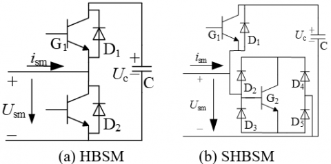
Figure 1. Topologies of the HBSM and the SHBSM
As shown in Figure 1, the HBSM has two parallel IGBTs, linked up with a diode, and a storage capacitor, while the SHBSM contains an IGBT with an antiparallel diode and a bidirectional controllable pass bridge, plus a storage capacitor. In normal operation, the upper and lower IGBTs are turned on and off alternatively to charge/discharge the storage capacitor and switch between the submodules. Under the same voltage, the SHBSM-MMC has more diodes than the HBSM. The additional diodes occupy a limited space and incur a low packaging cost, making the control system easier to implement.
2.2 SHBSM principle
The SHBSM follows the same principle with the HBSM in normal operation. When a charging current ism>0, the current path is ism- diode D1- capacitor C-ism and the storage capacitor is charged, if IGBT G1 is turned on and IGBT G2 is turned off, the current path is ism-D2-G2-D5-ism and the submodule is bypassed, if G1 is turned off and G2 is turned on. When ism<0, the current path is ism-C-G1-ism and the storage capacitor is discharged, if G1 is turned on and G2 is turned off; the current path is ism-D4-G2-D3-ism and the submodule is bypassed, if G1 is turned off and G2 is turned on. The switching states of the SHBSM are given in Table 1, where Ublk is the voltage across G2 when the fault current is blocked.
Table 1. The switching states of the SHBSM
|
G1 |
G2 |
Usm |
Current |
Operating status |
|
ON |
OFF |
+Uc |
Ism>0 |
Input discharge |
|
ON |
OFF |
+Uc |
Ism<0 |
Putting into charging |
|
OFF |
ON |
0 |
Ism<0 or Ism>0 |
Resection |
|
OFF |
OFF |
+Uc |
Ism>0 |
Blocking |
|
OFF |
OFF |
+Ublk |
Ism<0 |
Blocking |
3.1 Topology of SHBSM-MMC
Figure 2 shows the electrical quantity between the submodules of the SHBSM-MMC in normal operation. In the submodule, G1 and G2 are turned on alternately. Let n be the number of submodules put into operation by the upper and lower arms at any time in each phase. Then, the following equation can be derived:
$n{{U}_{\text{c}}}={{U}_{\text{dc}}}$ (1)
Figure 2. The topology of SHBSM-MMC
3.2 Fault cleaning mechanism
In the event of DC bipolar short-circuiting, the IGBT pulse signals in all submodules are blocked at the same time. The fault current path is cut off by the capacitor voltage, forcing the diode to reverse turn-off and the plurality of series connected IGBT to turn off.
(1) If the bridge arm current Ibrg is greater than zero, the back electromotive force (EMF) of the energy capacitor in the submodule is introduced to the loop (Figure 3).
Figure 3. Blocking the fault current in mode 1
After all the IGBTs are turned off, the internal current path of each submodule is connected in series by the diode and submodule capacitors. In this way, each current path passes through 2n diodes and capacitors. Each diode is subjected to reverse voltage at both ends, and forced to cut off reversely, thus blocking the fault current [5].
(2) If the bridge arm current is turned off, the short-circuit current path is cut off by G1 and G2 in the submodule (Figure 4). After all the IGBT pulses are blocked, all the IGBTs are turned off, which is equivalent to a distributed DC circuit breaker. In this way, the short-circuit current is directly cut off, such that the AC system cannot feed the power or current loop to the inverter.
Figure 4. Blocking the fault current in mode 2
3.3 Electrical stress analysis
In normal operation, the upper and lower IGBTs of the submodule are turned on and off alternatively. Thus, the voltage on each IGBT can be approximated as the capacitor voltage UC in the sub-module:
$U\text{IBGT}=U\text{C}$ (2)
In this case, the voltage across the bridge arm inductor is roughly equal to the instantaneous voltage of the common DC bus. Then, the DC short-circuit current can be expressed as:
$I\text{scd}=\frac{U\text{Lsum}}{L\text{sum}}\Delta T$ (3)
where, Lsum is the total inductance on the short circuit; ΔT is the response time from fault occurrence to system lockout.
Since the instantaneous short circuit current quickly falls to zero, the overvoltage that G2 can withstand can be expressed as
$U\text{G2}=\frac{L\text{sum}}{2n}\frac{\text{d}i\text{scd}}{\text{d}t}=\frac{L\text{sum}}{2n}\frac{I\text{scd}}{\Delta T\text{2}}$ (4)
where, ΔT2 is the time to cut off the fault current. From equations (3) and (4), it can be seen that the amplitude of the short-circuit current depends the bridge arm inductance and the system lock-up time. The shorter the lock-up time, the lower the amplitude of the short-circuit current. The short-circuit is terminated once the fault is removed. The amplitude of the short-circuit current is positively correlated with the back EMF. Therefore, the fault should be judged quickly to block the submodule as soon as possible [10].
In normal operation, the lower diodes are turned on and off alternately, but the electrical stress remains the same. Thus, the voltage across the diode satisfies:
$U\text{Dmax}=U\text{cmax}$ (5)
Once a fault occurs, the lower IGBT is instantaneously blocked, resulting in a large reverse voltage across the IGBT. In this case, the voltage is applied to the diode parallel to the IGBT.
$U\text{D}=\frac{U\text{G2}}{2}$ (6)
Because of the bridge arm inductance, G2 will face over voltage at both ends. Then, a high trigger consistency is required to block the current by turning off the IGBTs.
3.4 Design of hybrid topology
To cut off the DC fault, the IGBT pulse signal in all submodules of SHBSM-MMC must be blocked simultaneously. This raises a high requirement on the control system. Besides, the lower IGBT will have a spike overvoltage at turn-off, posing a threat to the IGBT safety. To solve this problem, this paper puts forward a hybrid topology for the SHBSM (Figure 5).
Figure 5. The hybrid topology
In the hybrid topology, the SHBSM and the HBSM are connected by a clamp diode, such that the fault current cut off by the lower IGBT can be transferred, and that the IGBT is subjected to the voltage of the entire bridge arm at the first turn-off. Then, a voltage condition occurs to prevent the IGBT from being burnt. The maximum voltage of diode D8 is Uc1+Uc2.
3.5 Fault cleaning mechanism of hybrid topology
(1) Figure 6 shows the fault current path (marked with a red arrow) after all the IGBT pulse signals are blocked under the DC fault when isc>0. In this case, diodes D1 and D3 of all submodules in the MMC are connected in series with capacitors C1 and C2, and the two capacitors are charged. Once the total capacitor voltage in the path surpasses the instantaneous AC side voltage, the diode is subjected to the back pressure and forced to be turned off, thus cutting off the fault current.
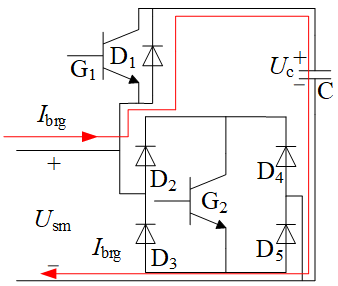
Figure 6. Blocking the fault current in mode 1
(2) Figure 7 shows the fault current path (marked with a red arrow) after all the IGBT pulse signals are blocked under the DC fault when isc<0.In this case, the clamped diode and the capacitor in the HBSM provide a path for the fault current, which prevents the G4 from directly breaking the fault current and precludes the overvoltage of the G4.
Figure 7. Blocking the fault current in mode 2
Then, the rated capacitor voltage of each submodule UC0 satisfies:
$nU\text{C0}=U\text{dc}$ (7)
where, n is the number of submodules on each bridge arm; Udc is the voltage of the DC positive pole to the negative pole. Without considering the bridge arm inductance, the relationship between the voltage amplitude umax of the MMC AC terminal and the DC voltage can be expressed as:
$u\text{max}=M\frac{U\text{dc}}{2}, 0<M<1$ (8)
Thus, once a DC fault occurs, the fault current should be blocked if the total capacitor voltage in the reverse series is greater than or equal to Udc/2. To this end, each bridge arm needs to invert n/2 pairs of the hybrid topology.
Our hybrid topology can relax the requirement. Under the fault current in Figure 7, if the trigger pulse of G4 in a submodule is blocked earlier than that of G4 in another submodule, the fault current of the early-blocked submodule will pass through diode D8. Then, capacitor C1 and diode D2 will circulate the current and charge DC capacitor C1. The collector-emitter voltage UCE of the early-locked G4 is clamped by diode D8 to the capacitor voltage +UC, aiming to prevent overvoltage or burning of the early-locked G4.
To sum up, our hybrid topology always provides a “diode–DC capacitor–diode” current path, whichever the current direction, allowing the DC capacitor to operate in a charged state. If the MMC adopts the hybrid topology in Figure 5, the late-locked submodule will route the fault current via D4-G4-D7-D2, while the early-locked submodule will route the fault current via D8-C1-D2. The DC fault current will be locked once the total capacitor voltage of all the blocked submodules exceeds the AC voltage. Thus, our hybrid topology does not need simultaneous locking of G4.
To simulate our hybrid topology, a 21-level double-ended MMC-HVDC example was set up on the PSCAD platform. The simulation parameters were configured as follows: the number of submodules per bridge, n=20; the submodule capacitance, 6000μF; the bridge arm inductance, 0.001H; the rated DC side voltage, 60kV; the submodule capacitance, 3kV; the occurrence time of the inter-pole short circuit, T=2.5s.
During the simulation, all IGBT pulses were blocked at T=2.501s, i.e. with a delay of 1ms, and the fault lasted for 0.1s. Then, the pulses were released at T=2.601s. The simulated results were measured by a converted through inverter side.
4.1 SHBSM-MMC simulated results
After it is blocked, the voltage across the lower IGBT equals the voltage that the AC system applies on both ends of the IGBT:
$U\text{IGBT}=\frac{\sqrt{3}U\text{S}}{2n}$ (9)
Since the IGBT directly breaks the fault current, a large back pressure occurs at both ends of the IGBT once it is locked up (Figure 8(a)). The lock-up current is blocked instantly, but the peak current occurs instantaneously. In the course of blocking, the submodule is subjected to sinusoidal AC voltage, which comes from the three-phase voltage of the AC system. As shown in Figure 8(b), quick protective measures are necessary to control the electrical stress on the devices in the converter station within the normal range. From Figure 8(c), it can be seen that the capacitor voltage is locked by instantaneous clamp. Under the control system, the capacitor voltage fluctuates around the rated voltage during normal operation. In other words, the capacitor voltage is close to the rated voltage when the lock is closed. After blocking, the bridge arm voltage equals the AC side voltage. The blocking induces a high instantaneous voltage on the bridge arm, due to the instantaneous moment of the bridge arm inductance. During the blocking period, the bridge arm voltage is the three-phase voltage of the AC system. When the fault is cleaned, the bridge arm voltage quickly returns to the normal level (Figure 8(d)). The above results show that the fault current is blocked rapidly, and the normal operation of the system is restored.
Overall, the SHBSM-MMC can quickly reset the DC fault current and fulfill the high triggering consistency, ensuring that the power devices are within the normal stress range.
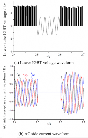
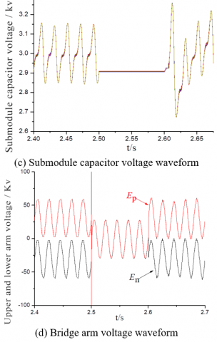
Figure 8. Simulated results of SHBSM-MMC
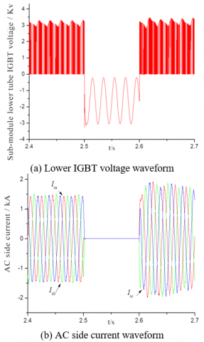
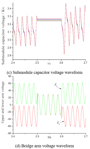
As shown in Figure 9(a), the lower IGBT voltage of the submodule has a small spike voltage, which prevents the IGBT from directly breaking the fault current and causes it to burn out. The AC side current is blocked instantaneously, cutting off the energy feeding path of the AC system (Figure 9(b)). Similar to the SHBSM-MMC, our hybrid topology locks up the submodule capacitor voltage instantly (Figure 9(c)). As shown in Figure 9(d), the bridge arm voltage has a small peak voltage at the moment of IGBT blocking, which is attributable to the $L\frac{\text{d}i}{\text{d}t}$ effect of the bridge arm inductance. However, the peak voltage is far lower than the bridge arm voltage of the SHBSM-MMC. The above simulated results show that our hybrid topology can quickly clean the fault current of DC side short circuiting, and eliminate the overvoltage on the IGBT.
Figure 9. Simulated results of hybrid topology
This paper puts forward a hybrid topology of SHBSM-HSBM, and establishes a double-ended MMC-HVDC system to identify the MMC fault self-cleaning capacity of the SHBSM. The fault cleaning effect of the hybrid topology was simulated on PSCAD platform. The main conclusions are as follows.
(1) The SHBSM has three more diodes than the HBSM. Despite a small cost increment, the MMC-HVDC with the SHBSM topology can automatically clean the DC fault current, while retaining the advantages of the HBSM.
(2) The proposed hybrid topology can solve the high requirement on trigger consistency, that is, all IGBT pulse signals must be blocked at the same time to clean DC fault current. The simulation shows that our hybrid topology can strictly block all IGBT pulse signals simultaneously, lowering the technical difficulty, the number of power devices and the cost of the MMC. Hence, the proposed hybrid topology has a huge application value.
The future research will explore the control and startup strategies for DC faults in MMC topology.
This work is supported by the Key R&D Program of Gansu Province, China (Grant numbers: 18YF1FA058) and the National Natural Science Foundation of China (Grant numbers: 51767014).
[1] Marquardt, R., Alesnicar, A. (2004). New concept for high voltage-modular multilevel converter. Proceedings of the IEEE Power Electronics Specialists Conference, Aachen, Germany, pp. 1-5.
[2] Shi, X., Wang, Z.Q., Liu, B., Liu, Y., Tolbert, L.M., Wang, F. (2014). Characteristic investigation and control of a modular multilevel converter-based HVDC system under single-line-to-ground fault conditions. IEEE Transactions on Power Electronics, 30(1): 408-421. https://doi.org/10.1109/TPEL.2014.2323360
[3] Shaik, K.P., Karimulla, S., Mohammad, I.S., Mohammad, M.H. (2018). Simulation of single phase buck boost matrix converter without commutation issues. European Journal of Electrical Engineering, 20(2): 205-214. https://doi.org/10.3166/EJEE.20.205-214
[4] Marquardt, R. (2010). Modular multilevel converter: An universal concept for HVDC-Networks and extended DC-Bus-applications. In The 2010 International Power Electronics Conference-ECCE ASIA, pp. 502-507. https://doi.org/10.1109/IPEC.2010.5544594
[5] Li, X.Q., Liu, W.H., Song, Q., Rao, H., Zhu, Z., Li, X.L. (2014). An enhanced MMC topology with DC fault clearance capability. Proceedings of the CSEE, 34(36): 6389-6397.
[6] Zhang, J., Zhao, C., Sun, H.F., Huang, X., Lu, Y., Qiu, P. (2014). Improved topology of modular multilevel converter and application. Transactions of China Electrotechnical Society, 29(8): 173-179.
[7] Antonopoulos, A., Angquist, L., Nee, H.P. (2009). On dynamics and voltage control of the modular multilevel converter. In 2009 13th European Conference on Power Electronics and Applications, pp. 1-10.
[8] Zhang, J., Zhao, C. (2015). The research of SM topology with DC fault tolerance in MMC-HVDC. IEEE Transactions on Power Delivery, 30(3): 1561-1568. https://doi.org/10.1109/TPWRD.2015.2399412
[9] Wu, J., Yao, L.Z., Wang, Z.B., Li, Y., Yang, B., Cao, Y.Z. (2015). The study of MMC topologies and their DC fault current blocking capacities in DC grid. Proceedings of the CSEE, 35(11): 2681-2694.
[10] Yang, X.F., Xue, Y., Zheng, T., Lin, Z.Q., Mu, Y.J., Chen, B.W., Igarashi, S. (2016). Novel modular multilevel converter with reverse blocking sub-modules. Proceedings of the CSEE, 36(7): 1885-1891. https://doi.org/10.13334/j.0258-8013.pcsee.2016.07.015
[11] Merlin, M.M.C., Green, T.C., Mitcheson, P.D., Trainer, D.R., Critchley, R., Crookes, W., Hassan, F. (2013). The alternate arm converter: A new hybrid multilevel converter with dc-fault blocking capability. IEEE Transactions on Power Delivery, 29(1): 310-317. http://dx.doi.org/10.1109/TPWRD.2013.2282171
[12] Li, B., He, J. (2016). Research on the DC fault isolating technique in multi-terminal DC system. Proceedings of the CSEE, 36(1): 87-95. http://dx.doi.org/10.13334/j.0258-8013.pcsee.2016.01.009
[13] Wang, C., Xu, J., Zhao, C. (2015). MMC based on single-clamp sub-module and improved topology schemes. Electric Power Automation Equipment, 35(9): 74-80.
[14] Wang, X., Lin, W.X., Wen, J.Y., Cheng, S.J. (2014). A new topology of sub-modules with DC fault current blocking capability and a new type of hybrid MMC converter. Proceedings of the CSEE, 34(29): 5171-5179. http://dx.doi.org/10.13334/j.0258-8013.pcsee.2014.29. 019
[15] Liu, J., Tai, N.L., Fan, C.J., Huang, W.T. (2015). Comments on fault handling and protection technology for VSC-HVDC transmission lines. Automation of Electric Power Systems, 39(20): 158-167. http://dx.doi.org/10.7500/AEPS20150125002
[16] Sun, X., Cao, S.D., Bu, G.Q., Wang, H.W., Lei, X., Lu, B.X. (2016). Construction scheme of overhead line flexible HVDC grid. Power System Technology, 40(3): 678-682.
[17] Xue, Y., Xu, Z. (2013). DC fault ride-through mechanism and improved topology scheme of C-MMC. Proceedings of the CSEE, 33(21): 63-70.
[18] Xu, Z., Xue, Y., Zhang, Z. (2014). VSC-HVDC technology suitable for bulk power overhead line transmission. Proceedings of the CSEE, 34(29): 5051-5062.
[19] Ding, Y., Su, J., Zhou, J. (2014). Analysis on fault current limitation and self-recovery of MMC based on clamp double sub-module. Automation of Electric Power Systems, 38(1): 97-103.
[20] Yang, X.F., Zhen, Q.L., Xue, Y., Lin, Z.Q., Chen, B.W. (2016). Review on topology and industry applications of modular multilevel converter. Power System Technology, 40(1): 1-10.
[21] Zhao, C., Xu, J., Li, T. (2013). DC faults ride-through capability analysis of Full-Bridge MMC-MTDC System. Science China Technological Sciences, 56(1): 253-261.
[22] Gowaid, I.A., Adam, G.P., Massoud, A.M., Ahmed, S., Holliday, D., Williams, B.W. (2014). Quasi two-level operation of modular multilevel converter for use in a high-power DC transformer with DC fault isolation capability. IEEE Transactions on Power Electronics, 30(1): 108-123. http://dx.doi.org/10.1109/TPEL.2014. 2306453
[23] Wang, S.S., Zhou, X.X., Tang, G.F., He, Z., Teng, L., Bao, H.L. (2011). Analysis of submodule overcurrent caused by DC pole-to-pole fault in modular multilevel converter HVDC system. Proceedings of the CSEE, 31(1): 1-7.
[24] Xu, Y.J., Luo, Y.H., Shi, T.T., Liu, Y.H. (2018). A new MMC sub-module with DC fault self-clearing ability and its hybrid topology. Power System Protection and Control, 46(7): 129-137.